Antiferromagnetism in RuO2 as -wave Pomeranchuk instability
Abstract
We present a computational study of antiferromagnetic transition in RuO2. The rutile structure with the magnetic sublattices coupled by -rotation leads to a spin-polarized band structure in the antiferromagnetic state, which gives rise to a -wave modulation of the Fermi surface in the spin-triplet channel. We argue a finite spin conductivity that changes sign in the plane is expected RuO2 because of this band structure. We analyze the origin of the antiferromagnetic instability and link it to presence of a nodal line close to the Fermi level.
Antiferromagnetic (AFM) metals have been attracting much interest recently due to their spintronic applications based on coupling between magnetic moments and charge current Wadley et al. (2016). While ubiquitous among transition metal oxides, antiferromagnetism in this group is typical for Mott insulators rather than metals. Metallic antiferromagnets can be found either doping Mott insulators as in cuprates, by replacing oxygen with more covalent ligands as in iron pnictides Kamihara et al. (2008) or CuMnAs Wadley et al. (2013), or by moving down the periodic table to less correlated transition metals. Itinerant antiferromagnetism, with magnetism and transport governed by the same electronic states, arises usually via the Slater mechanism Slater (1951). Nesting between parts of the Fermi surface (FS) produces an instability that is resolved by an AFM state, which is stabilized by gapping of the nested parts of FS. Such an AFM state reduces the translation symmetry of the system. Its band structure is not spin polarized since the spin-up and -down sublattices are connected by a sublattice translation within the AFM unit cell.
Structures with even number of magnetic atoms in the unit cell allow AFM ordering without breaking of translation symmetry. Ruthenium dioxide RuO2 with rutile structure, recently observed to be a room temperature antiferromagnet Berlijn et al. (2017); Zhu et al. (2019), is an example of such a material. In this Letter we report a computational study of RuO2 using density functional + dynamical mean-field theory (DFT+DMFT) as well as static Hartree-Fock (HF) techniques. We find that AFM order in RuO2 leads to a spin-polarized band structure. The distinct spin-up and spin-down FSs are rotated by along the crystallographic -axis with respect to each other. The AFM order thus can be viewed as a -wave Pomeranchuk instability in the spin-triplet channel Wu et al. (2007). We discuss the experimental implications and trace the origin of the AFM instability to a nodal line in the paramagnetic (PM) band structure located in the vicinity of Fermi level.
Starting from DFT electronic structure in the structure Berlijn et al. (2017) obtained with wien2k package Blaha et al. (2001), we constructed Wannier orbitals spanning the Ru 4 bands Kuneš et al. (2010); Mostofi et al. (2014). The tight-binding model was augmented by intra-atomic electron-electron interaction of the Slater-Kanamori form Slater (1960); Kanamori (1963)
where the indices , run over the orbital flavors on the same atom, whose site index was dropped for simplicity. The resulting Hubbard model was studied with DMFT and HF methods. The DMFT calculations employed the strong-coupling continuous-time quantum Monte Carlo method Werner et al. (2006); Boehnke et al. (2011); Hafermann et al. (2012); Hariki et al. (2015) and the density-density approximation () to . HF calculations with spin-orbit coupling (SOC), included a posteriori to the mean-field Hamiltonian, were performed to determine the orientation of the local moments in the AFM state. The impact of SOC on the band structure was found to be only minor in line with the conclusions of Ref. Jovic et al., 2018.
The calculations covered a wide range of , parameters and temperatures, summarized in the Supplemental Material (SM) SM . While size of the ordered moment varies with these parameters and among the two methods the general observations presented here are shared by all calculations. Quantitatively, the DMFT and HF electronic structures corresponding to the same ordered moment agree with each other and as well as with DFT+U calculations, as shown in SM SM . This observation suggests that staggered Weiss field due to the AFM order, a feature shared by all methods, is the dominant effect. In the following, we present HF (DMFT) results for (1.7) eV and (0.45) eV at (100) K.
Spin-polarized band structure. In Fig. 1a we show the AFM band structure obtained with DMFT. The band structure throughout the Brillouin zone (BZ) is spin-polarized, giving rise to a spin contrast shown in Fig. 1b. Special high-symmetry planes, discussed below, are an exception where spin-up and spin-down bands are degenerate. In Fig. 1c we present PM and AFM bands obtained with HF method. The ordered moment in the Wannier basis is in both cases. Apart from noticeable dynamical bandwidth renormalization absent in the HF spectra, we observe overall a good agreement between the HF and DMFT results. This suggests that the weak-coupling HF approach provides a reasonable description of the physics of RuO2 and we can use its simple structure to analyze the observed behavior.
Since both Ru1 and Ru2 sites with the anti-parallel spin moments fit in the rutile unit cell, the AFM order does not affect the translation symmetry. It reduces the point symmetry, however. The operations connecting the magnetic sublattices (mapping Ru1 to Ru2), e.g., the screw rotation, belong no more to the symmetry group. To do so they must be augmented with spin-inversion. As a result, the AFM band structure is spin-polarized with the two spin channels being coupled by -rotation. This distinguishes RuO2 from other antiferromagnets with spin-polarized bands, such as tetragonal CuMnAs Wadley et al. (2013) where the magnetic sublattices, and thus the spin-polarized bands, are connected by inversion symmetry. The spin-up and spin-down bands of RuO2 are degenerate (cross) along the planes, which are invariant under the glide plane connecting the magnetic sublattices. The same applies for planes and glide plane.
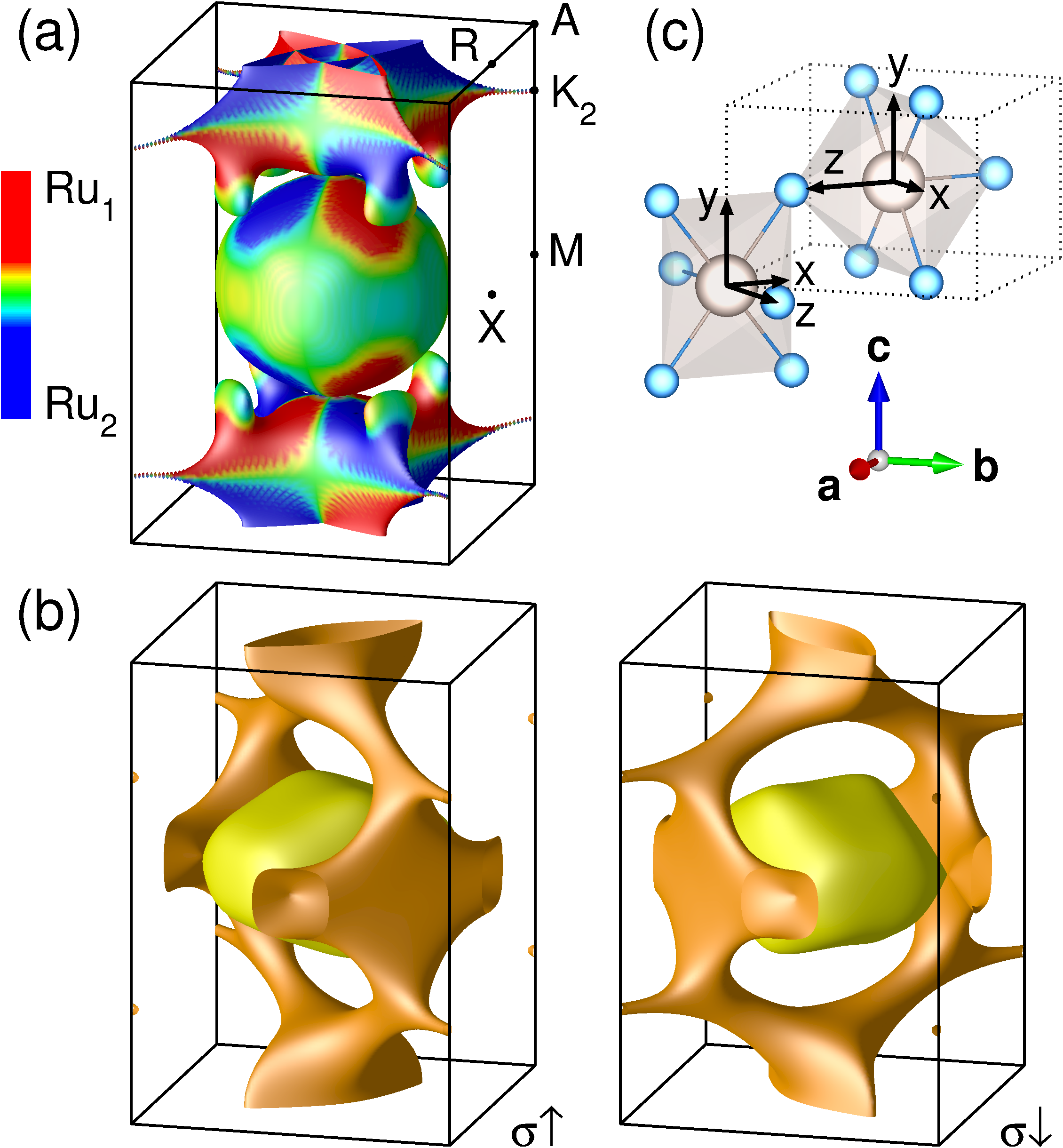
The spin polarized band structure gives rise to FS shown in Fig. 2b. The deformation of four-fold symmetric FS in Fig. 2a into a pair of two-fold symmetric FS connected by -rotation and spin inversion can be classified as -wave spin-triplet Pomeranchuk instability of the type in the notation of Ref. Wu et al. (2007). This type of spin-polarized FS implies a finite longitudinal spin conductivity in the -plane with opposite sign of in the (1,1,0) and (1,-1,0) directions, which vanishes along the crystallographic axes.
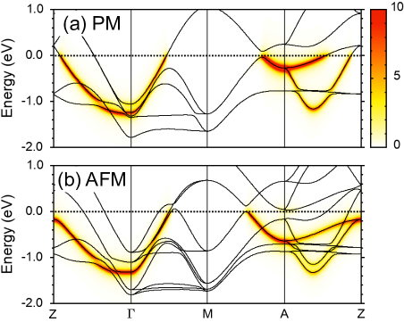
Apart from spin-polarization the AFM order causes changes of the band structure that can be detected with angle-resolved photoemission spectroscopy (ARPES). In Ref. Jovic et al. (2018), soft x-ray ARPES spectra obtained with -polarized light were reported. We have simulated -polarized ARPES spectra, assuming that the scattering plane is perpendicular to the -axis. The resulting spectra in the PM and AFM states are shown in Fig. 3. The spectra along and directions agree well with those of Fig. S3 of Ref. Jovic et al., 2018, while the weaker signal observed observed halfway between and should be silent according to our simulation 111This discrepancy could arise from complexities of the matrix-element effects (e.g. photon energy dependence) in ARPES spectra or surface effects. In the present simulation, the selection rule for the orbital excitation under the scattering plane perpendicular to the -axis and -polarized x-rays is taken into account.. Comparison of the PM and AFM bands reveals a sizable shift of the FS crossing point on with the onset of AFM order, while the crossing point on moves only slightly. The sharp experimental band observed along line does not produce any spin contrast. On the other hand well separated spin polarized bands predicted along the line by the present calculation have vanishing cross section for the polarization of incoming photons.
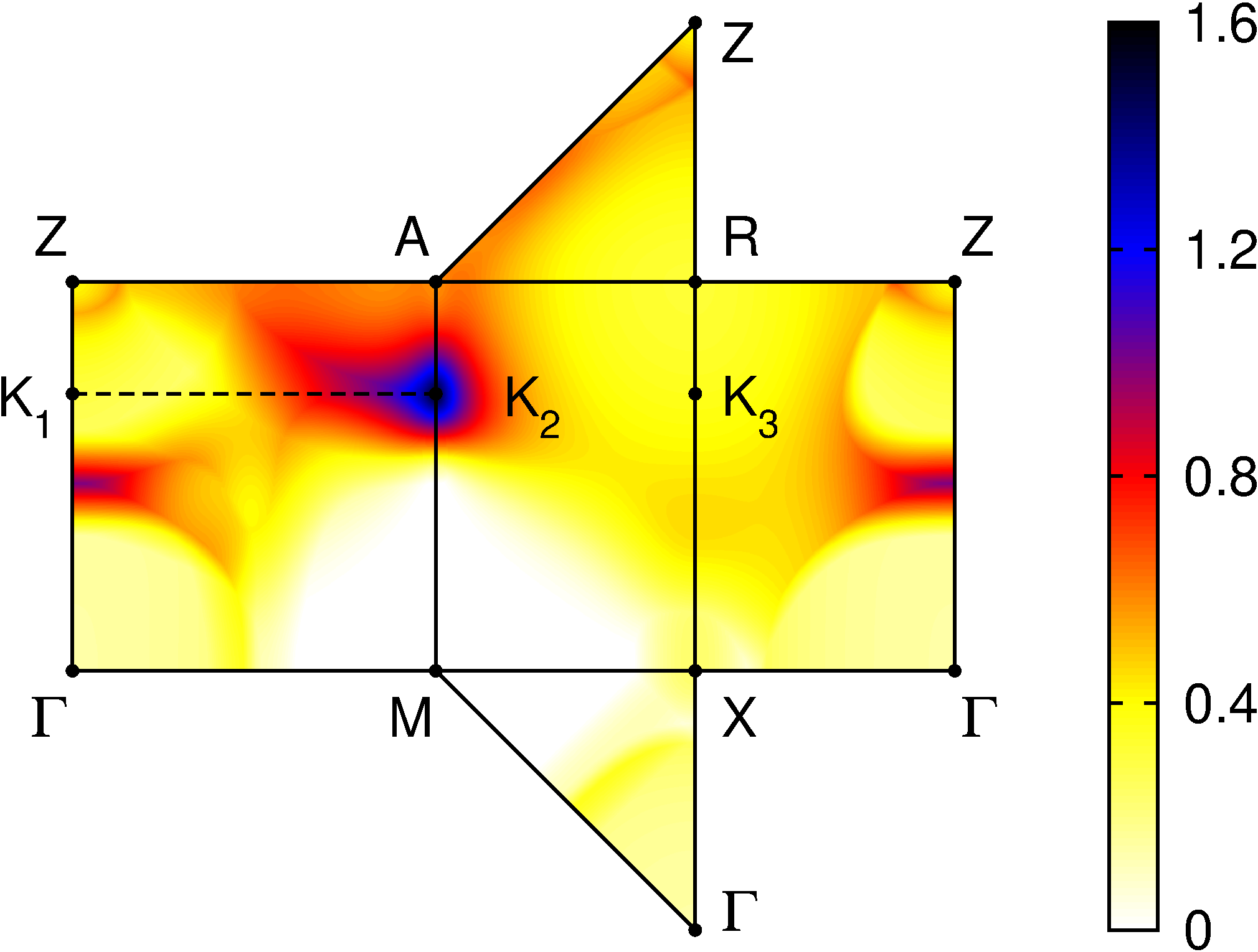
Origin of AFM instability. Similarity between the DMFT and HF results allows us to use the simpler HF approach to analyze the origin of AFM instability. The grand potential in the HF approach with mean-field is given by the sum of the eigenenergies of occupied single-particle states of the mean-field Hamiltonian (measured from the chemical potential) and a positive -dependent constant , where is the occupation number. The AFM state is stabilized if lowering of the first term overcomes the increase of the second one relative to the PM solution. To assess how different parts of BZ contribute to stabilization of the AFM order we plot the difference in Fig. 4. We find a hot spot around the point marked , which extends horizontally towards the zone center. This observation contrasts with the result of Ref. Berlijn et al. (2017) where a point on the line was identified as a hot spot destabilizing the PM phase. Large contributions to condensation energy are expected from regions where gaps open at the Fermi level. This is the case of the vicinity of , analyzed in Fig. 5.
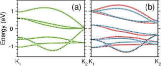
At the point the nodal line NDL1 of Ref. Jovic et al. (2018) reaches the edge of BZ. Together with the band sticking along vertical faces of BZ, this gives rise to a four-fold degenerate point, which happens to be very close to the Fermi level. The band structure in the vicinity of line has a simple explanation in terms of inter-atomic hopping. The relevant electronic states are formed by and orbitals in the local coordinates shown in Fig. 2a. Along the line the two Ru sites as well as and orbitals are decoupled and the dispersion is governed by hopping along chains of edge sharing RuO6 octahedra stretching along the -axis. The opposite sign of - and - hopping results in the crossing of the corresponding bands at . The different parity of the and bands with respect to -axis inversion explains their appearance/absence in the ARPES spectrum of Ref. Jovic et al. (2018).
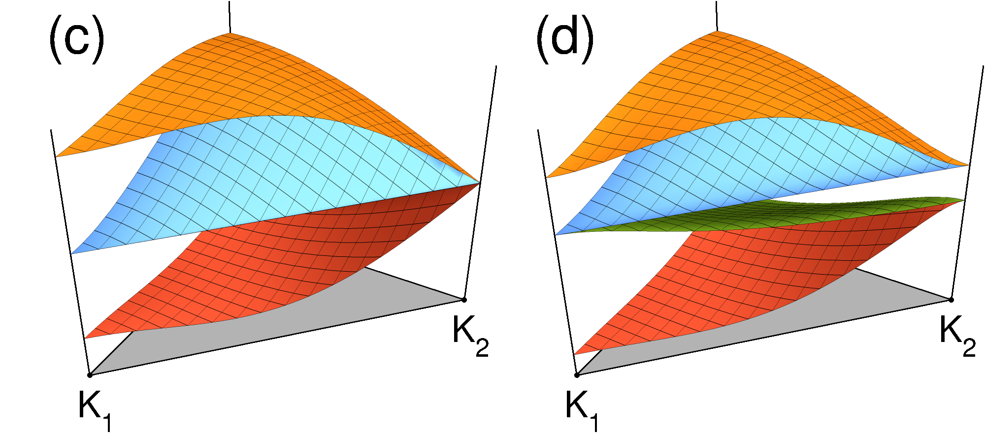
The dispersion in plane is governed by the inter-sublattice Ru1-Ru2 hopping (see SM SM for details). The nodal line NDL1 that is flat connecting and points in the -approximations, Fig. 5c, acquires some corrugation when long-range hopping and orbitals are included, see Fig. 5a and Ref. Jovic et al. (2018). The AFM order introduces a staggered potential with opposite sign in each spin channel. Its effect on HF bands along line is shown in Fig. 5b (both spin channels) and on the model bands in Fig. 5d (one spin channel). The gap opening by the staggered potential can be illustrated by expanding the tight-binding Hamiltonian to linear order around
| (1) |
in the basis formed by , , , and orbitals.
To open a gap by the staggered potential we need a (approximate) band crossing close to the Fermi level and hybridization between the magnetic sublattices (Ru1-Ru2) so that the band crossing is not just shifted to a different position in BZ. Such a band structure, described by Eq. 1, is found in the vicinity of NDL1.
In the PM state such -regions are characterized by rapid changes in the Ru1/Ru2 sublattice composition of the wave functions. In Fig. 2a we show the PM FS colored by the sublattice polarization (difference between Ru1 and Ru2 weight) of the corresponding wave functions. The hot spots in Fig. 4 correlate with red/blue boundaries in Fig. 2a where sublattice polarized bands meet. The sublattice polarization descends to a spin polarization in the AFM phase, Fig. 2b. On the other hand, the regions with fifty-fifty sublattice participation are insensitive to the staggered potential, e.g. in the plane, and PM and AFM FS essentially coincide with each other.
Finally, we discuss the role of SOC. The band structure calculations of Ref. Jovic et al. (2018) found a minor modifications of the band structure in the form of avoided band crossings. We find that gapping NDL1 due to SOC has only minor effect on the AFM instability. The impact on the HF band structure depends strongly on the type of mean-field decoupling, a deficiency that is not present in DMFT treatment. In the present work we have added SOC a posteriori to the converged HF, which has the similar effect as in DFT calculation Jovic et al. (2018). The band structures with and without SOC are compared in Fig. 5. The main effect of SOC is to break the spin isotropy reflected in magneto-crystalline anisotropy. The HF+SOC calculations yield Ru moments parallel to the -axis.
The rutile structure of RuO2 gives rise to several interesting phenomena. Šmejkal et al. Šmejkal et al. recently suggested realization of crystalline Hall effect in this material. The -wave modulation of FS results in a finite longitudinal spin conductivity with a sign change between (1,1,0) and (1,-1,0) directions. Another interesting question is response of the AFM structure to external magnetic field. Using the weak-coupling approach the authors of Ref. Wu et al., 2007 concluded that the order parameter (staggered moment in this case) aligns parallel to the external field. This is associated with an expansion of FS for the parallel spin component and shrinking of the anti-parallel one, with the consequence of breaking the four-fold symmetry in the charge channel. Such behavior of an antiferromagnet would be rather unusual and require extremely soft magnetic moments. We have investigated this possibility with HF calculations (without SOC), but found the conventional behavior with moments turning perpendicular to the external field with a small tilt into the field direction, in which case the symmetry between the spin-up and spin-down FS is reserved.
In conclusion, we have studied the antiferromagnetism of RuO2 using combinations of DFT band structure with HF and DMFT treatment of intra-atomic interaction. The AFM ordering in RuO2 can be classified as a spin-triplet -wave Pomeranchuk instability of FS. It gives rise to a spin-polarized band structure that leads to anisotropic spin-conductivity in the -plane. The source of AFM instability was traced to a nodal line that accidentally appears close to the Fermi level.
The authors thank W. E. Pickett, J. Železný and K. Yamagami for valuable discussions. K.H.A. and K.W.L are supported by National Research Foundation (NRF) of Korea Grant No. NRF-2016R1A2B4009579. A.H. and J.K. are supported by the European Research Council (ERC) under the European Union’s Horizon 2020 research and innovation programme (Grant Agreement No. 646807-EXMAG). Access to computing and storage facilities provided by the Vienna Scientific Cluster (VSC) is greatly appreciated.
References
- Wadley et al. (2016) P. Wadley, B. Howells, J. Železný, C. Andrews, V. Hills, R. P. Campion, V. Novák, K. Olejník, F. Maccherozzi, S. S. Dhesi, S. Y. Martin, T. Wagner, J. Wunderlich, F. Freimuth, Y. Mokrousov, J. Kuneš, J. S. Chauhan, M. J. Grzybowski, A. W. Rushforth, K. Edmond, B. L. Gallagher, and T. Jungwirth, Science 351, 587 (2016).
- Kamihara et al. (2008) Y. Kamihara, T. Watanabe, M. Hirano, and H. Hosono, J. Am. Chem. Soc. 130, 3296 (2008).
- Wadley et al. (2013) P. Wadley, V. Novák, R. P. Campion, C. Rinaldi, X. Martí, H. Reichlová, J. Zelezný, J. Gazquez, M. A. Roldan, M. Varela, D. Khalyavin, S. Langridge, D. Kriegner, F. Máca, J. Masek, R. Bertacco, V. Holý, A. W. Rushforth, K. W. Edmonds, B. L. Gallagher, C. T. Foxon, J. Wunderlich, and T. Jungwirth, Nat. Commun. 4, 2322 (2013).
- Slater (1951) J. C. Slater, Phys. Rev. 82, 538 (1951).
- Berlijn et al. (2017) T. Berlijn, P. C. Snijders, O. Delaire, H.-D. Zhou, T. A. Maier, H.-B. Cao, S.-X. Chi, M. Matsuda, Y. Wang, M. R. Koehler, P. R. C. Kent, and H. H. Weitering, Phys. Rev. Lett. 118, 077201 (2017).
- Zhu et al. (2019) Z. H. Zhu, J. Strempfer, R. R. Rao, C. A. Occhialini, J. Pelliciari, Y. Choi, T. Kawaguchi, H. You, J. F. Mitchell, Y. Shao-Horn, and R. Comin, Phys. Rev. Lett. 122, 017202 (2019).
- Wu et al. (2007) C. Wu, K. Sun, E. Fradkin, and S.-C. Zhang, Phys. Rev. B 75, 115103 (2007).
- Blaha et al. (2001) P. Blaha, K. Schwarz, G. K. H. Madsen, D. Kvasnicka, and J. Luitz, WIEN2K, An Augmented Plane Wave + Local Orbitals Program for Calculating Crystal Properties (Karlheinz Schwarz, Techn. Universität Wien, Austria, 2001).
- Kuneš et al. (2010) J. Kuneš, R. Arita, P. Wissgott, A. Toschi, H. Ikeda, and K. Held, Comp. Phys. Comm. 181, 1888 (2010).
- Mostofi et al. (2014) A. A. Mostofi, J. R. Yates, G. Pizzi, Y.-S. Lee, I. Souza, D. Vanderbilt, and N. Marzari, Comp. Phys. Comm. 185, 2309 (2014).
- Slater (1960) J. C. Slater, Quantum Theory of Atomic Structure (McGraw-Hill, 1960).
- Kanamori (1963) J. Kanamori, Progress of Theoretical Physics 30, 275 (1963).
- Werner et al. (2006) P. Werner, A. Comanac, L. de’ Medici, M. Troyer, and A. J. Millis, Phys. Rev. Lett. 97, 076405 (2006).
- Boehnke et al. (2011) L. Boehnke, H. Hafermann, M. Ferrero, F. Lechermann, and O. Parcollet, Phys. Rev. B 84, 075145 (2011).
- Hafermann et al. (2012) H. Hafermann, K. R. Patton, and P. Werner, Phys. Rev. B 85, 205106 (2012).
- Hariki et al. (2015) A. Hariki, A. Yamanaka, and T. Uozumi, J. Phys. Soc. Jpn. 84, 073706 (2015).
- Jovic et al. (2018) V. Jovic, R. J. Koch, S. K. Panda, H. Berger, P. Bugnon, A. Magrez, K. E. Smith, S. Biermann, C. Jozwiak, A. Bostwick, E. Rotenberg, and S. Moser, Phys. Rev. B 98, 241101 (2018).
- (18) See Supplemental Material for computational details, magnetic moment in a wide range of and parameters, comparison of DFT+U, HF and DMFT approaches, and inter-sublattice Ru1-Ru2 hopping, which includes Refs. Perdew et al. (1996); Anisimov et al. (1993); Jarrell and Gubernatis (1996); Wang et al. (2009); Mravlje et al. (2012); Hariki et al. (2017).
- Note (1) This discrepancy could arise from complexities of the matrix-element effects (e.g. photon energy dependence) in ARPES spectra or surface effects. In the present simulation, the selection rule for the orbital excitation under the scattering plane perpendicular to the -axis and -polarized x-rays is taken into account.
- (20) L. Šmejkal, R. González-Hernández, T. Jungwirth, and J. Sinova, arXiv:1901.00445.
- Perdew et al. (1996) J. P. Perdew, K. Burke, and M. Ernzerhof, Phys. Rev. Lett. 77, 3865 (1996).
- Anisimov et al. (1993) V. I. Anisimov, I. V. Solovyev, M. A. Korotin, M. T. Czyżyk, and G. A. Sawatzky, Phys. Rev. B 48, 16929 (1993).
- Jarrell and Gubernatis (1996) M. Jarrell and J. Gubernatis, Phys. Rep. 269, 133 (1996).
- Wang et al. (2009) X. Wang, E. Gull, L. de’ Medici, M. Capone, and A. J. Millis, Phys. Rev. B 80, 045101 (2009).
- Mravlje et al. (2012) J. Mravlje, M. Aichhorn, and A. Georges, Phys. Rev. Lett. 108, 197202 (2012).
- Hariki et al. (2017) A. Hariki, A. Hausoel, G. Sangiovanni, and J. Kuneš, Phys. Rev. B 96, 155135 (2017).