Inducing and controlling magnetism in the honeycomb lattice through harmonic trapping potential
Abstract
We study strongly interacting ultracold spin- fermions in a honeycomb lattice in the presence of a harmonic trap. Tuning the strength of the harmonic trap we show that it is possible to confine the fermions in artificial structures reminiscent of graphene nanoflakes in solid state. The confinement on small structures induces magnetic effects which are absent in a large graphene sheet. Increasing the strength of the harmonic potential we are able to induce different magnetic states, such as a Néel-like antiferromagnetic or ferromagnetic states, as well as mixtures of these basic states. The realization of different magnetic patterns is associated with the terminations of the artificial structures, in turn controlled by the confining potential.
I introduction
The discovery of graphene Geim (2009); Novoselov et al. (2005), a two-dimensional sheet of carbon atoms arranged on a honeycomb lattice, has generated a new field of research which attracted an unprecedented interest as it combines an almost ideal non-trivial quantum problem with extraordinary mechanical, electronic, thermal, and transport properties Novoselov et al. (2005); Castro Neto et al. (2009). From a more theoretical perspective, the rise of graphene has increased the interest in the properties of quantum particles on the honeycomb lattice.
Besides the synthesis of a variety of graphene-based systems, this has also pushed the community to devise quantum simulators of the honerycomb lattice using ultracold atoms Lee et al. (2009); Tarruell et al. (2012); Duca et al. (2015); Soltan-Panahi et al. (2011), which can access regimes which are not easily reached in solid state systems.
One of the most elusive properties of solid-state graphene systems is magnetism. Infinite, or very large, graphene sheets do not show magnetic ordering Chen et al. (2013), which is instead proposed and realized in nanoscopic structures composed by a small number of carbon atoms when the termination have a so-called zigzag pattern Nakada et al. (1996); Fernández-Rossier and Palacios (2007). However, the instability of zig-zag edges severely limits the realization of magnetic graphene nanostructures and the first solid experimental evidence is very recent Slota et al. (2018) .
Promising candidates for magnetism are nanoflakes Valli et al. (2016); Koop and Wessel (2017). Their theoretical phase diagram is quite rich, and it is characterized by a strong competition between short-range antiferromagnetic (AF) and long-range ferromagnetic (FM) correlations. The former are particularly strong in insulating half-filled flakes with one fermion per site, while the latter emerge when the density is reduced and the carriers become more mobile. In principle this competition might be exploited to manipulate the magnetic ground state by, e.g., electrostatic Kabir and Saha-Dasgupta (2014); Valli et al. (2016); Ganguly et al. (2017) or chemical doping Kang et al. (2011); Zou et al. (2015); Ortiz et al. (2016) and to engineer different kinds of spin filters Kang et al. (2011); Cao et al. (2011); Zou et al. (2015); Lundeberg and Folk (2009); Valli et al. (2018, 2019). This rich scenario is however so far largely unexplored owing to the technical difficulties to control the edges of solid-state graphene nanosystems.
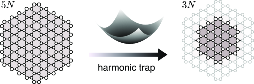
In this paper we propose an alternative route to induce magnetism in effective artificial graphene structures formed by cold atoms moving in optical lattices Bloch et al. (2008); Mazurenko et al. (2017) which overcomes the limitations of solid-state realizations. The idea is to engineer an optical lattice with the graphene honeycomb structure Lee et al. (2009); Tarruell et al. (2012); Duca et al. (2015); Soltan-Panahi et al. (2011) in the presence of a strong harmonic trapping potential which confines the fermions in a limited portion of the lattice, thus realizing an artificial nanostructure. A schematic illustration of this idea is depicted in Fig. 1. In what follows we show that this procedure leads to sufficiently well defined artificial edges which mirror the different edges of solid-state nanosystems. We demonstrate that, by continuously tuning the strength of the trapping potential, and thus the size of the artificial flake, we can induce magnetic phases starting from a non-magnetic system and we can induce transitions between different magnetic states with different arrangements of the spins. We will highlight that the effective flakes will be characterized by a spatially inhomogeneous distribution of the fermions, with a larger local density in the central region. This will enrich the scenario of the magnetic properties of the effective flakes with respect to graphene nanoflakes.
The paper is organized as follows: In Sec. II we introduce the model used to describe the graphene-like structure and give an overview of dynamical mean-field theory that is used to solve the system. In the Sec. III we discuss the two main results, namely the creation of the artificial nanostructures in optical lattices reminiscent of graphene nanoflakes (Sec. III.1) and the magnetic properties of the synthetic nanoflakes (Sec.III.2). Sec. IV is dedicated to concluding remarks.
II model and method
We model our artificial structure by a Fermi-Hubbard model with repulsive interactions on a two-dimensional honeycomb lattice
| (1) |
where () denotes the creation (annihilation) operator for spin-1/2 fermions and is the density operator at site for the two spin states, labeled by . is the total density on site . denotes the nearest-neighbour tunneling amplitude, the on-site repulsion while the chemical potential controls the number fermions. is a harmonic trapping potential, with the lattice coordinate and . In our calculations we consider a sites lattice with hexagonal shape and zigzag edges whose geometric center, , coincides with the minimum of the parabolic potential, as shown in the left panel of Fig. 1.
In the absence of the optical trap, on an infinite honeycomb lattice, this model displays a transition from a Dirac semimetal to an antiferromagnetic insulator at average density of one fermion per site (half-filling) Sorella and Tosatti (1992). A metallic state is generally found for any other number of fermions. The critical interaction strength for the onset of magnetism has been estimated to be Yunoki and Sorella (2006) via numerically exact Quantum Monte Carlo simulations of large lattices. On smaller systems with zigzag edges, an AF spin ordering establishes at the boundaries Fernández-Rossier and Palacios (2007); Kabir and Saha-Dasgupta (2014); Valli et al. (2016). Importantly, theoretical Valli et al. (2016) and experimental Magda et al. (2014) evidences suggest that this edge magnetism survives up to room temperature. As expected, AF order is favoured in half-filled systems, for which the Hubbard interaction is more effective in localizing the carriers. The general expectation is that, when the density deviates substantially from half-filling, delocalized metallic states are favoured. The free motion of carriers in a metallic state destroys the AF ordering, while they it can coexist with a FM order, which is not spoiled by the motion of carriers. This leads to a competition between AF and FM tendencies which is mainly determined by the density. It is therefore very interesting to address this issue in our inhomogeneous system where the local density changes as we move from the center to the edge of the system.
We solve the model using a real-space dynamical mean-field theory (DMFT) Georges et al. (1996); Capone et al. (2007); Weber et al. (2012); Snoek et al. (2008) approach, which has been previously used to study inhomogeneous systems, such as cold atoms Snoek et al. (2008); Amaricci et al. (2014); Gorelik et al. (2010), and nanostructures Valli et al. (2010, 2012); Schüler et al. (2017), including isolated graphene nanoflakes Valli et al. (2016). In the homogeneous case DMFT approximates the lattice self-energy of the interacting many-body problem with a local, momentum-independent, self-energy which, however, retains the full frequency dependence which allows to capture non-trivial quantum correlations characteristic of strongly correlated systems Georges et al. (1996). In order to treat an intrinsically inhomogeneous system and the confinement effects induced by the parabolic potential we need to relax this approximation using real-space DMFT, in which the self-energy remains local but it acquires a dependence on the specific lattice, i.e., .
In order to explore extensively the dependence of parameters we focus on finite artificial flakes, following previous calculations in a solid-state set-up Valli et al. (2016, 2018). We borrow from these works the choice to start from the 150-site cluster that we label as (according to a notation where is the number of sites on an edge). This cluster contains smaller hexagonal nanoflakes (, , …) with the same symmetry, as well as flakes with different edge termination (bearded), which are shown in Fig. 2(f), which can all in principle be stabilized by the trapping potential.
This allows to prove whether our protocol to confine atoms in effective nanostructures actually works in configurations which have already been tested. In this light we refrain from a detailed comparison with potential realizations with actual cold-atom experiments, which we postpone to future research. We notice that a similar scheme, where the optical trapping is used to induce quantum states in an optical lattice loaded with ultracold fermions, has been realized in Ref. Chiu et al. (2018).
III Results
III.1 Artifical Nanostructures
As discussed in the following, the electronic distribution and the magnetic ordering of the fermions in the trapping potential depend on the value of the local repulsion, which in cold-atom experiments can easily be controlled via tuning the strength of the optical lattice and the scattering length, when Feshbach resonances are available. We consider two case: and . The first value corresponds to a realistic choice for actual graphene, and it falls in the range where the semimetal/AF insulator transition takes place for the infinite honeycomb lattice Yunoki and Sorella (2006); Sorella and Tosatti (1992). The latter is sufficient to put any graphene structure deeply in the Mott state, where the fermions are described as localized spins interacting via a Heisenberg exchange.

We will first consider a system with the same number of fermions per each spin species , where is the total number of fermions, which in fixed. This is the standard situation for a cold-atom experiment, where the number of fermions in each species is conserved. As a second step we will also release this constraint, allowing the system to relax in a state with a finite global magnetization (i.e., with ). This situation would be realized in systems in which spin-flip processes are possible as a consequence of the coupling to an external environment or the inclusion of a small artificial spin-orbit coupling. From a theoretical perspective, this will be useful to clarify the tendency towards ferromagnetic ordering with a finite magnetization for some values of the interaction and of the trapping potential.
In all our calculations we consider , which coincides with the number of sites composing the nanoflake with zigzag edges. Thus, if the fermions can be trapped in the portion of space corresponding to the flake we would have one fermion per site (half-filling), which is the ideal situation for the onset of AF ordering, at least for a homogeneous system. On the other hand, for our system of 150 sites, the average filling is , i.e. a small density which makes interactions marginally effective. Therefore, in the absence of trapping potential we have no magnetic effects and the fermions are spread over the whole system also for large interaction strength.
This non-magnetic state is the starting point to introduce the harmonic potential. Increasing the strength , we progressively localize the fermions in the central region. This is demonstrated in Figs. 2(a-c), where we show the map of the local density on the whole system for calculations with 111When we release the equal-population constraint the changes in the density profile are very small and they are basically invisible in the plots. In the absence of the trap we recover a nearly homogeneous system (the small deviation is due to boundary effects) with for every site . Conversely for trapping potential strength the fermions are spatially localized within a reduced region around the center of the trap. The sharpness of the confinement depends on the value of the Coulomb repulsion.
In order to investigate this aspect, in Figs. 2(d,e) we show the radial profile of the local density as a function of the distance from the trap center for different values of the trapping potential. In shallow traps (e.g., and ) the fermion distribution is only weakly affected by the Coulomb repulsion due to the low average local density. As the trap deepens, the fermions tend to leave the boundaries to pack in the central region, and we witness an important effect of the repulsive interaction, which competes with the spatial charge accumulation. This effect is clear at . For relatively weak repulsion , as in Figs. 2(a,d), the charge accumulates towards the center of the trap, where we approach the maximum local density allowed by Pauli principle. Therefore, even if the fermions are localized in a region , the distribution is not uniform within the confinement region. At instead, as in Figs. 2(c,e), the fermions are Mott localized, and energetically costly double occupancies are strongly suppressed throughout the lattice. The tendency to reduce double occupancy contrasts the packing of fermions in the center of the trap and favors single occupation . In the strong-coupling (Mott) regime, most of the fermions are confined within a region , characterized by a nearly constant local density of , with a sharp drop at this effective boundaries. The competition between the trapping potential and the repulsion results in a smaller structure, almost homogeneously filled, which appears as a promising effective nanoflake. Our results directly reflect the incompressible nature of the Mott insulator, where the configuration with singly-occupied sites is highly favoured and robust with respect to the packing effect of the trapping potential. In contrast, in the weak- and intermediate-coupling regimes the system is a quantum fluid with a finite compressibility, which allows charges to accumulate in the center of the trap.
In Figs. 2(d,e) we denoted by vertical lines the radii corresponding to the edge sites of different hexagonal nanoflakes (, , and ) as labeled in Fig. 2(f). At , the sharp edge observed in the strong coupling regime coincides with that of the 3N nanoflake with zigzag edges which we already identified as a promising candidate for the emergence of magnetism because it can a host a half-filled configuration for the chosen total number of particles.
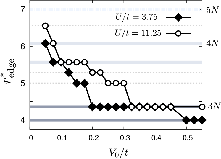
Before probing the magnetic properties of the artificial flake, we introduce a concrete definition of the effective edge . In Fig. 3 we plot as a function of the estimate of given by the position where the derivative of the density with respect to the position is maximal. Obviously, this definition has a degree of arbitrariness, but we have verified that different criteria provide the same result for large interactions, while some intrinsic ambiguity is present for small interactions. We marked as horizontal lines the positions of the edge sites as in Fig. 2. Upon increasing the fermionic cloud is attracted towards the center of the trap and its effective size is reduced. The contraction is faster at weak coupling with respect to strong coupling because the Coulomb repulsion acts as internal pressure competing with the trapping potential. Interestingly, in both regimes the system evolves through a series of effective flakes of different sizes. The 3N zigzag-edged flake is the most stable artificial structure, due to the initial choice of , and it is realized in a wide range of trapping potential strength.
III.2 Magnetism
We are now in the position to test whether the effective nanostructures that we have defined actually support magnetic ordering. Therefore in Fig. 4 we report color maps of the local magnetization along the -direction for the two values of interaction and three values of trapping potential used in Fig. 1. Red (blue) indicates a positive (negative) magnetization. Since the honeycomb lattice is bipartite, i.e., it can be divided in two sub-lattices A and B, such that sites of A are only connected with sites of B and vice versa, we can define a perfect AF state when the magnetization of sublattice A is the opposite of that of sublattice B , while a FM has the same magnetization on the two sublattices. A ferrimagnetic state is characterized by the presence of both a staggered and a uniform magnetization. In a non-magnetic state we have vanishing local magnetic moments . The results in Fig. 4 show a rich landscape of magnetic solutions which depend from the effective radius and the density distribution of the artificial flakes.
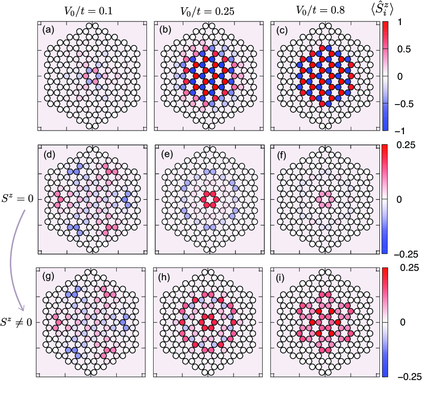
We start presenting results where we impose that the total number of up and down fermions is conserved and , or , where . We first consider results in the strong-coupling regime, where the emergence of an effective half-filled 3N nanoflake is clear, as shown by our data for . In the absence of a trapping potential, or for very shallow ones, the fermion density is low on every site (we remind that at ) and the flake is not magnetic (not shown). As the fermions are attracted towards the center of the trap, as in Fig. 4(a,b), we observe a clear AF pattern in the region of the inner rings, where while in the region where (quarter-filling) we find weakly FM islands. In Fig.4(c) we show that increasing leads to a dramatic enhancement of the magnetic moments, which form Néel AF state extended over the whole occupied central region. The character of the magnetic ordering of this half-filled structure is not surprising and it can be easily understood in terms of the strong-coupling limit of the Hubbard model, that leads to an effective Heisenberg model with a nearest-neighbor exchange coupling which leads to an AF ordering on the honeycomb lattice. The magnetic response confirms the formation, in the strong-coupling regime, of a well-defined effective flake, with properties reminiscent of an isolated graphene nanoflake, and proves that a simple change of the trapping potential can induce a magnetic state. The results in the strong coupling limit do not change if we relax the constraint, confirming that the AF solution is the actual groundstate of the system.
At intermediate interaction (e.g., for ) the evolution of the magnetic properties in Fig 4(d-f) is richer and more peculiar, as a result of a less pronounced tendency towards the formation of magnetic moments and the more ambiguous definition of an artificial edges. On the other hand, as discussed in previous work on graphene nanoflakesValli et al. (2016), densities different from one fermion per site favor FM correlations which are more compatible with metallic behavior. In our artificial nanoflake, this leads to a non-trivial evolution as a function of characterized by the competition between AF and FM correlations.
For shallow traps, the fermions are spread over a relatively large area, and AF ordering establishes in the central region, even if weaker than in the large- case. In the outer region we observe the development of small FM islands which are ordered in a staggered pattern around a hexagonal ring as shown in Fig. 4(d). This suggests the emergence of long-range AF correlations between FM domains at distances , mediated by the short-range (i.e., ) Heisenberg exchange. For deeper traps the packing towards the center is stronger because of the smaller repulsion. Once the occupation of the sites in the inner region becomes close to 2 the tendency towards AF order is washed away, and the center of the trap tends to host a FM island surrounded by a nonmagnetic region and an external ring where the fermions have the opposite spin with respect to the center. When the trapping potential becomes even larger (Fig. 4(f) for ) the magnetic moments become smaller because of the increased density in the center of the trap.
Our results directly demonstrate that tuning the trapping potential and the interaction strength we can induce magnetism or change completely its nature. For example if we change the interaction strength at fixed we can induce a transition between a FM and AF states (panels (b) and (e) or (c) and (f) of Fig. 4).
Finally, as anticipated above, we relax the the constraint. This protocol, which would require to include some mechanism able to flip the spins of the atoms, is chosen in order to better highlight the tendency towards FM that we have identified for the case with moderate electron-electron interaction. In contrast with the large- case, here we find that the system indeed minimizes its energy by polarizing the fermionic spins. In the third row of Fig. 4 we show these results. In particular if we compare panel (h) with panel (e) and panel (i) with panel (f) we find a clear enhancement of the FM correlations which invade a larger portion of the effective flake and, for the largest value of the potential that we considered we obtain a FM polarization spread over the whole effective flake.
IV Conclusions
In this work we have shown that a trapping potential can induce a variety of magnetic phases in an otherwise non-magnetic honeycomb lattice. In particular, a parabolic potential can be used to trap the fermions in artificial nanoflakes, which inherits the properties that have been widely studied in a solid-state framework. The trapping is most effective for strong fermion-fermion repulsion, underlining the important effect of interactions in the realization of well-defined artificial edges. Our work shows a novel route to induce magnetism in artificial graphene nanostructures, and it is expected to be robust with respect to details of the system, i.e., actual size and number of fermions as long as the interactions can be made sufficiently strong to reach the Mott regime.
Also when it is difficult to establish a direct correspondence with solid-state systems, because the trapping leads to strongly inhomogeneous density distributions, we find a competition between FM and AF tendencies. This leads to a tunable system evolving from a weak antiferromagnet to a ferromagnet. The magnetic ordering is also expected to be reflected in the transport properties, leading to highly non-trivial spin transport. The possibility to induce different magnetic states could be exploited to investigate of spin-filter Valli et al. (2018) and spin-valve effects within transport experiment in optical lattices Greiner et al. (2001); Mandel et al. (2003).
We acknowledge support from H2020 Framework Programme, under ERC Advanced Grant No. 692670 “FIRSTORM” and MIUR PRIN 2015 (Prot. 2015C5SEJJ001) and SISSA/CNR project "Superconductivity, Ferroelectricity and Magnetism in bad metals" (Prot. 232/2015). A.V. acknowledges financial support from the Austrian Science Fund (FWF) through the Erwin Schrödinger fellowship J3890-N36.
References
- Geim (2009) A. K. Geim, Science 324, 1530 (2009).
- Novoselov et al. (2005) K. S. Novoselov, A. K. Geim, S. V. Morozov, D. Jiang, M. I. Katsnelson, I. V. Grigorieva, S. V. Dubonos, and A. A. Firsov, Nature 438, 197 EP (2005).
- Castro Neto et al. (2009) A. H. Castro Neto, F. Guinea, N. M. R. Peres, K. S. Novoselov, and A. K. Geim, Rev. Mod. Phys. 81, 109 (2009).
- Lee et al. (2009) K. L. Lee, B. Grémaud, R. Han, B.-G. Englert, and C. Miniatura, Phys. Rev. A 80, 043411 (2009).
- Tarruell et al. (2012) L. Tarruell, D. Greif, T. Uehlinger, G. Jotzu, and T. Esslinger, Nature 483, 302 EP (2012).
- Duca et al. (2015) L. Duca, T. Li, M. Reitter, I. Bloch, M. Schleier-Smith, and U. Schneider, Science 347, 288 (2015).
- Soltan-Panahi et al. (2011) P. Soltan-Panahi, J. Struck, P. Hauke, A. Bick, W. Plenkers, G. Meineke, C. Becker, P. Windpassinger, M. Lewenstein, and K. Sengstock, Nature Physics 7, 434 EP (2011).
- Chen et al. (2013) L. Chen, L. Guo, Z. Li, H. Zhang, J. Lin, J. Huang, S. Jin, and X. Chen, Scientific Reports 3, 2599 (2013).
- Nakada et al. (1996) K. Nakada, M. Fujita, G. Dresselhaus, and M. S. Dresselhaus, Phys. Rev. B 54, 17954 (1996).
- Fernández-Rossier and Palacios (2007) J. Fernández-Rossier and J. J. Palacios, Phys. Rev. Lett. 99, 177204 (2007).
- Slota et al. (2018) M. Slota, A. Keerthi, W. K. Myers, E. Tretyakov, M. Baumgarten, A. Ardavan, H. Sadeghi, C. J. Lambert, A. Narita, K. Müllen, and L. Bogani, Nature 557, 691 (2018).
- Valli et al. (2016) A. Valli, A. Amaricci, A. Toschi, T. Saha-Dasgupta, K. Held, and M. Capone, Phys. Rev. B 94, 245146 (2016).
- Koop and Wessel (2017) C. Koop and S. Wessel, Phys. Rev. B 96, 165114 (2017).
- Kabir and Saha-Dasgupta (2014) M. Kabir and T. Saha-Dasgupta, Phys. Rev. B 90, 035403 (2014).
- Ganguly et al. (2017) S. Ganguly, M. Kabir, and T. Saha-Dasgupta, Phys. Rev. B 95, 174419 (2017).
- Kang et al. (2011) J. Kang, F. Wu, and J. Li, Applied Physics Letters 98, 083109 (2011).
- Zou et al. (2015) F. Zou, L. Zhu, and K. Yao, Scientific Reports 5, 15966 EP (2015).
- Ortiz et al. (2016) R. Ortiz, J. L. Lado, M. Melle-Franco, and J. Fernández-Rossier, Phys. Rev. B 94, 094414 (2016).
- Cao et al. (2011) C. Cao, Y. Wang, H.-P. Cheng, and J.-Z. Jiang, Applied Physics Letters 99, 073110 (2011).
- Lundeberg and Folk (2009) M. B. Lundeberg and J. A. Folk, Nature Physics 5, 894 EP (2009).
- Valli et al. (2018) A. Valli, A. Amaricci, V. Brosco, and M. Capone, Nano Letters 18, 2158 (2018).
- Valli et al. (2019) A. Valli, A. Amaricci, V. Brosco, and M. Capone, Phys. Rev. B 100, 075118 (2019).
- Bloch et al. (2008) I. Bloch, J. Dalibard, and W. Zwerger, Rev. Mod. Phys. 80, 885 (2008).
- Mazurenko et al. (2017) A. Mazurenko, C. S. Chiu, G. Ji, M. F. Parsons, M. Kanász-Nagy, R. Schmidt, F. Grusdt, E. Demler, D. Greif, and M. Greiner, Nature 545, 462 EP (2017).
- Sorella and Tosatti (1992) S. Sorella and E. Tosatti, Eur. Phys. Lett. 19, 699 (1992).
- Yunoki and Sorella (2006) S. Yunoki and S. Sorella, Phys. Rev. B 74, 014408 (2006).
- Magda et al. (2014) G. Z. Magda, X. Jin, I. Hagymási, P. Vancsó, Z. Osváth, P. Nemes-Incze, C. Hwang, L. Biró, and L. Tapasztó, Nature 514, 608 (2014).
- Georges et al. (1996) A. Georges, G. Kotliar, W. Krauth, and M. J. Rozenberg, Rev. Mod. Phys. 68, 13 (1996).
- Capone et al. (2007) M. Capone, L. de’ Medici, and A. Georges, Phys. Rev. B 76, 245116 (2007).
- Weber et al. (2012) C. Weber, A. Amaricci, M. Capone, and P. B. Littlewood, Phys. Rev. B 86, 115136 (2012).
- Snoek et al. (2008) M. Snoek, I. Titvinidze, C. Tőke, K. Byczuk, and W. Hofstetter, New Journal of Physics 10, 093008 (2008).
- Amaricci et al. (2014) A. Amaricci, A. Privitera, and M. Capone, Phys. Rev. A 89, 053604 (2014).
- Gorelik et al. (2010) E. V. Gorelik, I. Titvinidze, W. Hofstetter, M. Snoek, and N. Blümer, Phys. Rev. Lett. 105, 065301 (2010).
- Valli et al. (2010) A. Valli, G. Sangiovanni, O. Gunnarsson, A. Toschi, and K. Held, Phys. Rev. Lett. 104, 246402 (2010).
- Valli et al. (2012) A. Valli, G. Sangiovanni, A. Toschi, and K. Held, Phys. Rev. B 86, 115418 (2012).
- Schüler et al. (2017) M. Schüler, S. Barthel, T. Wehling, M. Karolak, A. Valli, and G. Sangiovanni, Eur. Phys. J. Special Topics 226, 2615 (2017).
- Chiu et al. (2018) C. S. Chiu, G. Ji, A. Mazurenko, D. Greif, and M. Greiner, Phys. Rev. Lett. 120, 243201 (2018).
- Note (1) When we release the equal-population constraint the changes in the density profile are very small and they are basically invisible in the plots.
- Greiner et al. (2001) M. Greiner, I. Bloch, T. W. Hänsch, and T. Esslinger, Phys. Rev. A 63, 031401 (2001).
- Mandel et al. (2003) O. Mandel, M. Greiner, A. Widera, T. Rom, T. W. Hänsch, and I. Bloch, Phys. Rev. Lett. 91, 010407 (2003).