Length measurement and stabilization of the diagonals of a square area laser gyroscope
Abstract
Large frame ring laser gyroscopes are top sensitivity inertial sensors able to measure absolute angular rotation rate below prad/s in few seconds. The GINGER project is aiming at directly measuring the Lense-Thirring effect with an precision on an Earth based experiment. GINGER is based on an array of large frame ring laser gyroscopes. The mechanical design of this apparatus requires a micrometric precision in the construction and the geometry must be stabilized in order to keep constant the scale factor of the instrument. The proposed control is based on square cavities, and relies on the length stabilization of the two diagonals, which must be equal at micrometric level. GP2 is the prototype devoted to the scale factor control test. As a first step, the lengths of the diagonals of the ring cavity have been measured through an interferometric technique with a statistical accuracy of some tens of nanometers, and they have been locked to the wavelength of a reference optical standard. Continuous operation has been obtained over more than 12 hours, without loss of sensitivity. GP2 is located in a laboratory with standard temperature stabilization, with residual fluctuations of the order of 1 ∘C. Besides the demonstration of the control effectiveness, the analysis of the Sagnac frequency demonstrates that relative small and low-cost ring lasers (around one meter of side) can also achieve a sensitivity of the order of nrad/s in the range Hz in a standard environment, which is the target sensitivity in many different applications, such as rotational seismology and next generation gravitational waves detectors.
1 Introduction
Large frame Ring Laser Gyroscopes (RLG), which exploit Sagnac effect, are the most sensitive devices for detecting absolute angular motions in a huge range of frequency, extending from kHz down to DC [1, 2]. GINGER (Gyroscopes IN General Relativity) is a project to build a large-frame 3-dimensional array of ring laser gyroscopes to be mounted inside the underground Gran Sasso Laboratory (LNGS). The Ginger final aim is to measure the Earth angular velocity in the laboratory co-rotating frame , and to compare it with the Earth angular velocity as observed in the Cosmic inertial frame . General Relativity Theory (GR) foresees that in low field approximation[3]
| (1) |
where (De Sitter or geo-electric effect) and (Lense-Thirring or geo-magnetic effect) take into account the GR effects [4] induced respectively by the Earth mass and the Earth angular momentum. For this purpose it is necessary an instrumental accuracy of the order of rad/s. Such an accuracy offers also the possibility of measuring fundamental geodetic parameters related to the fluctuations of the Earth rotational velocity and of the Earth axis orientation, the so-called length of the day and polar motion. In the geodetic observatory of Wettzell (Germany)[5] the ”Gross ring” (G) has already demonstrated a sensitivity of rad/s, not far from the GR test requirement. Since G is based on a monolithic design, which cannot be extended to an array, a new modular heterolithic design is required for GINGER. To study this new idea and to validate the site, a square 3.6 m side ring-laser based on an heterolithic structure, named GINGERINO [6],has been mounted in the underground INFN Gran Sasso National Laboratories (LNGS). It showed that continuous data taking is feasible with high sensitivity and duty cycle over [6, 7].
In general the response of a RLG to a rotation is given by the Sagnac frequency :
| (2) |
where is the area included by the optical path, the perimeter length, the laser wavelength, is the angle between the area versor of the RLG and the angular rotation axis. For a RLG rigidly connected to the soil, is the Earth rotation rate. For a RLG lying on an horizontal plane, is the colatitude angle, while for a RLG oriented with the axis parallel to Earth rotation axis is zero, and the Sagnac frequency has a maximum. The GINGER design is based on a square cavity, and the control of the scale factor (the ratio area over perimeter) relies on the accurate measurement and control of the diagonal lengths. Indeed, the important feature of a square cavity, is that the four mirrors define three resonant cavities: the square one and the two linear Fabry-Pérot resonators along the diagonals.
At present the control scheme [8, 9] is under test by using a dedicated RLG named GP2. It foresees first to align the square cavity and then to control the geometry through the length of the two diagonals. In this way the heterolithic structure can guarantee the same performances, in term of geometrical and thermal stability, of a monolithic one. The control procedure will work in two steps. In the first step the two diagonals are carefully measured and compared. Since the ring laser emission frequency is related to the ring perimeter length, it is possible to implement a procedure to optimize the geometry of the ring optical path by acting on the corner mirrors, as theoretically described in [9]. It is possible to obtain a path which is as close as possible to a square by measuring the laser frequency at the same time with the diagonal lengths. In the second step, during the GINGER operation, the optical path geometry will be actively stabilized, by locking the diagonal lengths to an external reference wavelength standard, also acting on the corner mirrors. From an experimental point of view the diagonal lengths can be easily optically exploited, since they constitute two Fabry-Pérot cavities, so that standard metrological techniques can be used. In these conditions, according to our analysis, a long term stability of the scale factor of the order of can be obtained. This is the needed stability for the test of the Lense-Thirring effect, if the error in the positions of the mirrors with respect to the perfect geometry is lower than m. The GP2 prototype has been installed in a laboratory of the basement of the INFN Pisa building, with the purpose of studying the experimental details of these procedures. In the following, after a brief description of the GP2 apparatus, we will give an overview of the metrological techniques, and the first results on the scale factor control circuit are reported.
2 Experimental Set-up
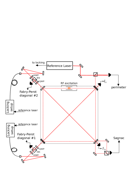
GP2 is a square ring resonator, 1.6 m in side, mounted on a a granite table. A pyrex capillary, 4 mm inner diameter, is inserted along one side, where the gas discharge is excited. The gas is an He-Ne mixture, with a 1:1 ratio of the two isotopes 20Ne and 22Ne [5]. Typical partial pressures are of the order of 20 Pa and 500 Pa for Ne and He respectively. The scheme of the optical setup is shown in Fig. 1 The granite support is fixed to a concrete basement tilted following the local latitude, . Then, the ring axis is almost parallel to the Earth rotation axis, so that the disturbances on the Sagnac signal induced by local tilts are minimized.
GP2 has been built as a test bench to develop the optics and the electronics to be implemented on GINGERINO and later on GINGER. It is located inside a quite noisy environment, so that very high sensitivity measurements are not feasible. That’s why we mounted on it high quality mirrors, but not the top quality ones as used by GINGERINO. The mirrors have 2 m curvature radius and total losses, estimated by a measured ring down time of s.
The mechanical design of GP2 is quite different from that used in our previous prototype G-Pisa [10] and then in GINGERINO [6]. Each corner mirror is mounted on a piezoelectric slide (PZT) that can move along the diagonal direction within an m range. One of the corner is equipped with two more piezo actuators in order to give a tri-axial Cartesian movement. As said above, the important feature of GP2 is that the four mirrors define, besides the square ring resonator, two Fabry-Pérot along the diagonals. Each linear cavity is optically interrogated by injecting a light beam coming from the same external stabilized laser source. In order to avoid optical noise injection, this laser works at a slightly different frequency from that of the ring laser emission .
The geometry stabilization procedure requires information both on the ring perimeter and on the diagonal lengths. The perimeter could be measured in two different ways. By using the self-beat note technique, or by measuring with an external reference. In the first case the ring laser is driven in a multimode regime, so that different longitudinal modes generate on a fast photodiode a beat-note at a frequency -multiple of the Free Spectral Range (FSR) of the ring cavity. Then, the ring perimeter can be deduced as /FSR . This technique is very easy to be implemented, but multi-mode operation can produce a decrease of sensitivity. This technique was successfully applied to the G0 ring operating in Canterbury (NZ) [11], which had an excellent Sagnac signal also in presence of multimode operation. It was however observed that the spectrum of the secondary modes were not stable. We tested this technique on GP2, and we observed a decay of the fringe contrast, which in the worst case dropped from over to under . We then applied the alternative technique, by using an external laser as a reference. By combining one of the output beams of the ring with the reference laser beam on a fast photodiode, we obtain a signal at the difference of the frequencies. This method requires a laser source with an high level of accuracy, but it does not affect at all the quality of the Sagnac signal. As a reference, we use a Helium-Neon laser stabilized on a saturated absorption transition of molecular Iodine; it was produced for us by the Institute of Laser Physics in Novosibirsk. [8].
However, for the stabilization of the the scale factor, it’s not sufficient the control of the perimeter, and it’s also needed to measure and to control accurately the diagonal lengths [9]. For this purpose, a fraction of the reference laser radiation is injected, through a polarization maintaining single-mode fibers, into the Fabry-Pérot resonators build by the diagonal opposite mirrors. In a first step each cavity is locked through a Pound-Drever-Hall (PDH) control circuit to the reference laser frequency, by acting on the mirrors by the (PZT). In this way the cavity length is forced to be an integer multiple of the laser wavelength. In the second step, the absolute value of each diagonal lengths is found, by measuring the frequency of a Voltage Controlled Oscillator (VCO), while it is locked to a multiple of the Fabry-Pérot free spectral range (FSR). The two values are acquired, and each cavity length is evaluated by using the relation FSR. This technique was described in details in [8] and it was successfully tested on two 1.5 m long FP resonant cavities resting on an optical table.
The application to GP2 was not straightforward because the PZT actual bandwidth is reduced by the massive vessel, whose mass is about 3 kg. The PZT effective bandwidth is no more than a few Hz, while, in our laboratory condition, the cavities noise in the acoustic band is larger, of the same order of the laser one. Then, a simple PDH is not able to work correctly. That’s why we separated the servo loop in two parts, and we implemented different low frequency and high frequency controls. The low frequency component of the actuation signal is used, with an integration time of 12.5 s, to drive the PZT, while the high frequency component drives a VCO acting through an acousto-optics modulator (AOM) on the frequency of the radiation in order to keep the laser locked to the Fabry-Pérot cavity resonance in the acoustic band. In short, at acoustic frequency, it is not the cavity that follows the laser, but the noise that affects the cavity is added to the laser. It is not a real correction, but it allows us to implement the slow stage of the lock loop. The addiction of this fast opto-electronic control improved greatly the performance of the system and we obtained in this way the results discussed in the present paper. The details of the electronic circuits for measuring and locking each diagonal are shown in Fig. 2. The injected laser field is modulated as:
| (3) |
where is the optical frequency of the carrier, MHz is the PDH modulation frequency to lock the carrier, is the modulation frequency for the cavity dynamic resonance excitation (in our case FSR MHz and ), kHz is the frequency of the dithering applied to for the down-convertion of the FSR resonance signal, and , and are the respective modulation amplitudes.
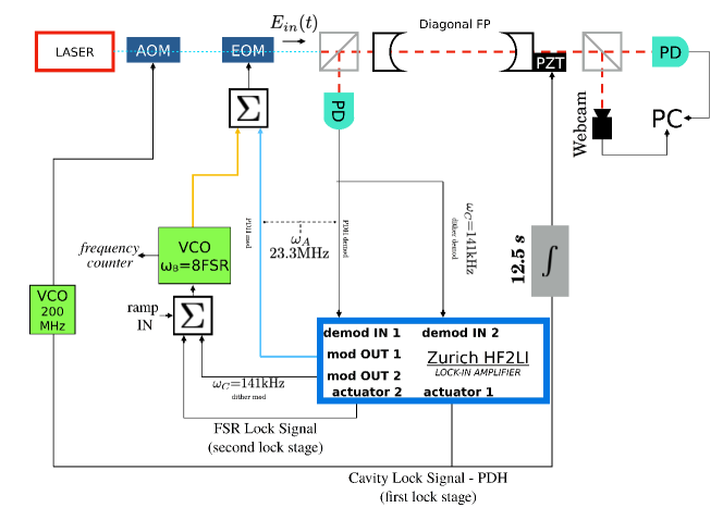
As shown in Fig. 2, the core of each control system is a Zurich Lock-in Amplifier HF2LI, a digital lock-in that generates the two modulation frequencies and , demodulates the signals, and generates the two PID (Proportional Integrative Derivative) correction signals for the two locking steps. The frequency of the VCO locked to the FSR is read by a two channels frequency meter that was referred to a rubidium clock. The relative error of the diagonal length is proportional to , so we chose as a compromise with the maximum allowed AOM frequency.
3 Experimental results and data analysis
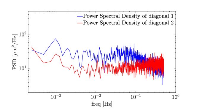
By using the optimized PID parameters generated by the Zurich Lock-in Amplifiers, we performed a simultaneous, about 12 hours long, measurement of both the diagonal lengths with a sampling rate of 1 data per second. The histogram of the results follows a Gaussian shape for both diagonals, with a peak value of 2262.7699 mm and 2261.5515 mm and a Half Width Half Maximum, respectively, of 1.8 m and 2.0 m. The first evidence is that there is a difference between the lengths of the two diagonals larger than expected. This difference is more than 1.2 mm, that is too large to be corrected just acting on the PZT slides. The Gaussian profile of the measurements distribution is demonstrated also by the flat trend of the power spectral density, which shows a typical white noise behaviour, see Fig.3. Then, we can also estimate the statistical accuracy of both measurements as nm for the longest diagonal and nm for the shortest one. Both of these values are consistent with the requirements for GINGER. In addition, the absence of a flicker noise bias makes possible to increase the accuracy increasing the measurement time.
We have tested the effectiveness of the technique of locking the diagonal length by measuring GP2 Sagnac signal over one day both with diagonals locked and unlocked. The data were processed following the analysis scheme developed for GINGERINO [7]. The Sagnac frequency, the intensities of the two counter-propagating beams and the monitor of the discharge fluorescence were recorded at 5 ksample/s acquisition rate. In the analysis, the portions of data affected by split mode or mode jumps were removed [7]. Fig. 4 compares the reconstructed angular rotation rate in locked (red curve) and in free running condition (blue curve). In locked operation the duty cycle was over , while in free running condition it dropped down to . It is as well evident that the free running data show larger perturbations.
GP2 is oriented at the maximum Sagnac signal; then it should measure the modulus of the Earth rotation rate. From data taken during locked operation, we can evaluate an averaged value of the rotation rate rad/s, which is consistent with the value of Earth rotation rate (Fig. 4, black horizontal line) rad/s.
GP2 is affected by large perturbations, being located in the basement of a building of the Physics Department of the University of Pisa in a laboratory where the temperature is stabilized at K. The long term fluctuation of the average value of the reconstructed angular rotation rate in free running operation is however of the order of , that is more than one order magnitude larger then expected by simply considering the effect on the scale factor of the thermal expansion. We can explain this large deviation as an effect of the back-scattering of the laser radiation on the optical cavity mirrors, which is very sensitive to the geometry, as discussed in [7, 12].
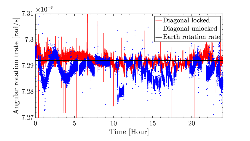
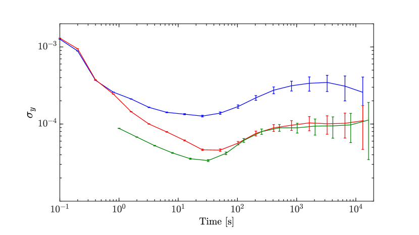
Fig. 5 shows the Allan deviation in the two cases. A sensitivity better than of nrad/s is obtained at 1 second of measurement, with a minimum of nrad/s at s of integration time.
4 Discussion and Conclusions
We showed a scale factor control technique for a large frame RLG system, which is based on the active control of the lengths of the diagonals of the square cavity, and on their accurate measurement . The technique to measure the diagonal lengths has been developed and tested on the GP2 prototype. The obtained accuracy is compliant with the requirements for GINGER (m error in the difference between the two values), which is aiming at the Lense-Thirring test at precision. Two test runs with diagonals locked and unlocked have been performed. The analysis has shown a duty cycle around , while the active locking is on and around in the uncontrolled case. In term of sensitivity the short time response is similar in the two cases, while the long term one is a factor 3 better in the controlled case. The test has shown as well the necessity to expand the bandwidth of the control loop. For this purpose it will be necessary to reduce the load of the actuators; in the present scheme the PZT actuators move the whole mirror holder. Considering that GP2 is done utilizing granite and steel, with our laboratory thermal conditions the long term stability of the scale factor should be around 1 part . The observed one is a factor worse, further studies and tests are necessary in order to investigate whether the long term response could be improved. An important improvement would be obtained by a better equalization of the two diagonal lengths, which is unfeasible with the present apparatus. Moreover, GP2 is located in a quite noisy environment and its mirrors are not top quality ones. In the future the test will be repeated by installing better mirrors, by acting on both mirrors for each cavity, in order to reduce changes on the back-scattered light, and by improving the shielding of the the RLG from external disturbances such as air flow, etc.
Anyway, this test shows that a middle size RLG can work continuously in a standard laboratory with a sensitivity of the order of a few nrad/s in the range 0.01-10 Hz. A range that can be extended at lower frequency by an effective geometry control. This result also demonstrates that relative small, with an area of the order of 1 , RLGs have a potential utility as very sensitive sensors of ground tilting. We note that Sagnac effect is sensitive to the rotation relative to an inertial frame and therefore is not affected by Newtonian noise while, on the contrary, balance tiltmeter are sensitive to rotation relative to the local direction. This kind of properties is rather timely, for application in future generation gravitational waves research and for seismological study in general.
References
- [1] Karl Ulrich Schreiber and Jon-Paul R. Wells “Invited Review Article: Large ring lasers for rotation sensing” In Review of Scientific Instruments 84.4, 2013, pp. 041101 DOI: 10.1063/1.4798216
- [2] W Z Korth et al. “Passive, free-space heterodyne laser gyroscope” In Classical and Quantum Gravity 33.3, 2016, pp. 035004 URL: http://stacks.iop.org/0264-9381/33/i=3/a=035004
- [3] Angela Di Virgilio et al. “GINGER: A feasibility study” In The European Physical Journal Plus 132.4, 2017, pp. 157 DOI: 10.1140/epjp/i2017-11452-6
- [4] F. Bosi et al. “Measuring gravitomagnetic effects by a multi-ring-laser gyroscope” In Physical Review D 84.12 American Physical Society, 2011, pp. 122002 DOI: 10.1103/PhysRevD.84.122002
- [5] Karl Ulrich Schreiber et al. “The Large Ring Laser G for Continuous Earth Rotation Monitoring” In Pure and Applied Geophysics 166.8, 2009, pp. 1485–1498 DOI: 10.1007/s00024-004-0490-4
- [6] Jacopo Belfi et al. “Deep underground rotation measurements: GINGERino ring laser gyroscope in Gran Sasso” In Review of Scientific Instruments 88.3, 2017, pp. 034502 DOI: 10.1063/1.4977051
- [7] J Belfi et al. “Analysis of 90 day operation of the GINGERINO gyroscope” In Appl. Opt. 57.20 OSA, 2018, pp. 5844–5851 DOI: 10.1364/AO.57.005844
- [8] Jacopo Belfi et al. “Interferometric length metrology for the dimensional control of ultra-stable ring laser gyroscopes” In Classical and Quantum Gravity 31.22, 2014, pp. 225003 DOI: 10.1088/0264-9381/31/22/225003
- [9] Rosa Santagata et al. “Optimization of the geometrical stability in square ring laser gyroscopes” In Classical and Quantum Gravity 32.5, 2015, pp. 055013 DOI: 10.1088/0264-9381/32/5/055013
- [10] Jacopo Belfi et al. “A 1.82 m 2 ring laser gyroscope for nano-rotational motion sensing” In Applied Physics B: Lasers and Optics 106.2, 2012, pp. 271–281 DOI: 10.1007/s00340-011-4721-y
- [11] J Holdaway et al. “Self-locked operation of large He–Ne ring laser gyroscopes” In Metrologia 49.3, 2012, pp. 209 URL: http://stacks.iop.org/0026-1394/49/i=3/a=209
- [12] J Belfi et al. “Active control and sensitivity of the ”G-Pisa” gyrolaser” In Nuovo Cimento B 125.5-6, 2010, pp. 557–567 DOI: 10.1393/ncb/i2010-10859-5