Scalable Hardware-Efficient Qubit Control with Single Flux Quantum Pulse Sequences
Abstract
The hardware overhead associated with microwave control is a major obstacle to scale-up of superconducting quantum computing. An alternative approach involves irradiation of the qubits with trains of Single Flux Quantum (SFQ) pulses, pulses of voltage whose time integral is precisely equal to the superconducting flux quantum. Here we describe the derivation and validation of compact SFQ pulse sequences in which classical bits are clocked to the qubit at a frequency that is roughly a factor 5 higher than the qubit oscillation frequency, allowing for variable pulse-to-pulse timing. The control sequences are constructed by repeated streaming of short subsequence registers that are designed to suppress leakage out of the computational manifold. With a single global clock, high-fidelity (%) control of qubits resonating at over 20 distinct frequencies is possible. SFQ pulses can be stored locally and delivered to the qubits via a proximal classical Josephson digital circuit, offering the possibility of a streamlined, low-footprint classical coprocessor for monitoring errors and feeding back to the qubit array.
I INTRODUCTION
A fault-tolerant quantum computer will possess a computational power far exceeding that of any classical computer Feynman (1982), and superconducting integrated circuits are a promising physical platform for the realization of scalable qubits Clarke and Wilhelm (2008). While the error thresholds of the two-dimensional surface code are within reach Fowler et al. (2012); Barends et al. (2014), quantum error detection involves a massive hardware overhead: estimates suggest that a general-purpose fault-tolerant quantum computer will require millions of physical qubits, far beyond current capabilities. Conventionally, qubit control pulses are generated by single-sideband modulation of a microwave carrier tone; accurate control of both the in-phase and quadrature pulse amplitudes allows arbitrary rotations on the Bloch sphere Motzoi et al. (2009); Lucero et al. (2010); Chow et al. (2010); Chen et al. (2016). In order to minimize crosstalk between neighboring qubit channels, it is generally necessary to arrange the qubit array so that devices are biased at a handful of distinct operating frequencies; this approach makes it possible to address a large-scale multiqubit circuit with a small number of carrier tones, resulting in a significant hardware savings Asaad et al. (2016). In addition, there have been proposals to recycle pulse waveforms across the qubit array Versluis et al. (2017). However, the control waveform that is delivered to the qubit is the convolution of the applied waveform with the transfer function of the wiring in the qubit cryostat, which in general is not well controlled. As wiring transfer functions can vary substantially across the array, it is not clear that recycling of control waveforms will allow high-fidelity control. Moreover, the separate high-bandwidth control lines for each qubit channel entail a massive heat load on the millikelvin stage. Finally, the significant latency associated with the round trip from the quantum array to the room-temperature classical coprocessor will limit the performance of any scheme to use high-fidelity projective measurement and feedback to stabilize the qubits Vijay et al. (2012); Campagne-Ibarcq et al. (2013); Ristè et al. (2012).
An alternative approach is to control the quantum array using a classical coprocessor that is integrated tightly with the qubits at the millikelvin stage. Recently we proposed an approach to coherent control involving irradiation of the qubit with trains of quantized flux pulses derived from the Single Flux Quantum (SFQ) digital logic family. Here, classical bits of information are stored as the presence or absence of a phase slip across a Josephson junction in a given clock cycle Likharev and Semenov (1991); the phase slip results in a voltage pulse whose time integral is precisely quantized to , the superconducting flux quantum. For typical parameters, SFQ pulse amplitudes are of order 1 mV and pulse durations are around 2 ps, roughly two orders of magnitude shorter than the typical qubit oscillation period. As a result, the SFQ pulse imparts a delta function-like kick to the qubit that induces a coherent rotation in the qubit subspace McDermott and Vavilov (2014). In the first experimental implementation of this idea, gate fidelity was limited by spurious quasiparticle generation by the dissipative SFQ pulse driver, which was integrated on the same chip as the qubit circuit Leonard et al. (2019). In next-generation devices, it is expected that segregation of classical control elements and quantum elements on the two separate chips of a multichip module (MCM) will lead to a significant suppression of quasiparticle poisoning McDermott et al. (2018). Ultimately, the fidelity of naive, resonant SFQ pulse trains will be limited by leakage out of the computational subspace, with achievable fidelity around for typical values of qubit anharmonicity and gate times around 20 ns. This fidelity is likely insufficient for fault-tolerant operations in a large-scale surface code array.
In order to achieve SFQ-based gates with fidelity well beyond threshold, it is possible to clock SFQ bits to the qubit at a higher rate, allowing for SFQ pulse trains with variable pulse-to-pulse separation. In previous work, genetic algorithms were used to derive optimized pulse sequences that lead to very low leakage and gate fidelities better than 99.99% Liebermann and Wilhelm (2016). However, the number of bits required to achieve high fidelity was rather high, and the genetic approach provides no intuition as to why a particular sequence yields good performance. While this proof-of-principle demonstration suggests that SFQ control sequences might offer a low-footprint alternative to conventional microwave sequences, the following questions remain:
-
•
What is the minimum number of classical bits needed to control a qubit to a given level of fidelity?
-
•
Is it possible to achieve high-fidelity control of qubits at different frequencies using a single global clock, as would be ideal for the surface code?
In this work, we describe a method to derive hardware-efficient SFQ control sequences for scalable qubit control: SCALable Leakage Optimized Pulse Sequences (SCALLOPS). The sequences are built up from short subsequences consisting of 35-55 classical bits that are repeatedly streamed to the qubit. Leakage is minimized at the subsequence level; because the subsequences are short, it is possible to perform efficient search over the subsequence space in order to optimize gate fidelity. For SFQ clock frequency roughly a factor 5 greater than the characteristic qubit frequency, we achieve high-fidelity qubit rotations for a large number of discrete qubit frequencies, as required for low-crosstalk control of a large-scale qubit array designed to implement the surface code.
This manuscript is organized as follows. In Section II we present a simple analytic framework for the study of SFQ-based pulse sequences. In Section III we introduce the key features of the SCALLOPS approach: (1) a palindromic sequence construction consisting of symmetric pulse pairs that suppresses errors within the qubit subspace; (2) accurate control of qubits resonating at a number of discrete frequencies by repeated streaming of a short pulse subsequence; and (3) a normal graph algorithm to minimize leakage from the computational subspace at the subsequence level. Finally, in Section IV we conclude and provide a perspective on the hardware requirements for the implementation of SCALLOPS.
Throughout this paper, we consider a fixed SFQ clock frequency of 25 GHz, so that SFQ pulses are delivered to the qubit at intervals that are integer multiples of the 40 ps clock period. In addition, we consider transmon qubits with fixed anharmonicity of 250 MHz, where is the qubit transition frequency and is the transition frequency between the qubit state and the noncomputational state. Finally, for the sake of concreteness we target high fidelity for a single gate, the rotation; the SCALLOPS approach is readily generalized to arbitrary single-qubit sequences.
II Model for SFQ Control of a Transmon Qubit
II.1 General Model
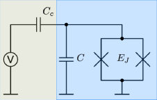
We consider a conventional transmon qubit Koch et al. (2007) coupled via a small capacitance to an SFQ driver modeled as a time-dependent voltage source , as drawn in Fig. 1. The Hamiltonian of the undriven transmon is written as
| (1) |
where and are the charge and phase operators of the transmon, is the transmon Josephson energy, and is the sum of the coupling capacitance and the transmon self capacitance . can be diagonalized in closed form, with the resulting energy eigenfunctions and energies represented by the Mathieu functions and coefficients.
Interaction between the transmon and the SFQ pulse driver adds the following term to the Hamiltonian:
| (2) |
where the SFQ pulse satisfies the condition . Since the pulse width (around 2 ps) is much less than the Larmor period (around 200 ps) of the transmon, we model the SFQ pulse as a Dirac delta function: . The charge operator can be constructed in the basis of once is diagonalized. The free evolution of the transmon then becomes
| (3) |
The time evolution operator for a transmon subjected to an SFQ pulse is McDermott and Vavilov (2014)
| (4) |
II.2 Three-level Model
It is advantageous to restrict the size of the transmon Hilbert space in order to accelerate the search for high-fidelity pulse sequences. Since leakage outside the computational subspace is dominated by population of the first noncomputational state , we truncate the transmon to a three-level qutrit; subsequent sequence validation will be performed on a more complete model of the transmon consisting of 7 states. Within the three-level subspace, the operators and take the form
| (5) | |||
| (6) |
Here, we have introduced the notation ; represents the fractional anharmonicity of the transmon; and .
Next, we derive the three-level matrix form for the free evolution of the transmon and for the evolution of the transmon subjected to a single SFQ pulse. The free evolution is given by the diagonal matrix . In the qubit subspace, the effect of is clearly a precession at the rate . For the time evolution under a single SFQ pulse, we can write
| (7) |
where
| (8) |
is the tip angle associated with a single SFQ pulse. Using the Cayley-Hamilton theorem on , we obtain the property , which yields for even and for odd . We then expand and regroup Eq. (7):
| (9) |
The two sums in Eq. (9) yield
| (10) |
where .
To see the effect of a single SFQ pulse, we compare this time evolution to a -rotation by angle in the qubit subspace:
| (11) |
We observe that: (1) within the three-level model, the SFQ pulse provides a rotation in the qubit subspace that is slightly smaller than ; and (2) leakage from state to state is first order in , while leakage from state to state is second order in .
II.3 Pulse Sequences and Gate Fidelity
The above analysis shows that it is impossible to perform coherent qubit rotations with a single SFQ pulse without incurring significant excitation of noncomputational states. However, composite sequences consisting of multiple SFQ pulses spaced by appropriate time intervals can achieve low leakage and high gate fidelity. More specifically, we consider a high-speed SFQ clock that delivers pulses to the transmon according to a vector of binary variables , where if no SFQ pulse is applied on the clock edge and if an SFQ pulse is applied. Using these expressions, the total time evolution operator of the gate , time ordered in terms of clock edges, can be written as
| (12) |
Here, is the number of clock cycles in the sequence and is the clock period.
We evaluate the fidelity of the gate as in Bowdrey et al. (2002);
| (13) |
where the summation runs over the six states aligned along the cardinal directions of the Bloch sphere
| (14) | ||||
and the gate gate is represented by the following matrix in the qubit subspace:
| (15) |
The crux of the problem then becomes proper selection of so that becomes a high-fidelity gate.
III SCALLOP sequences
III.1 Symmetric SFQ Pulse Pairs
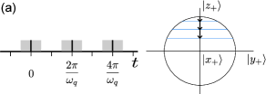
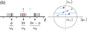
In the simplest scheme for SFQ-based coherent control, one applies a regular train of SFQ pulses that is synchronized to the qubit oscillation period (Fig. 2a); this is the situation considered in McDermott and Vavilov (2014). In this method, because in the qubit subspace, only the desired -rotations can be induced by and ; however, leakage out of the qubit subspace can be significant. To attain higher fidelity, it is necessary to clock SFQ pulses to the qubit at a higher rate and to employ more sophisticated sequences. When the qubit is no longer resonant with the SFQ clock, , and the time evolution of an arbitrary sequence of and is generally not confined to -rotations. To ensure high overlap with the target -rotation, we construct a composite sequence built up from symmetric pairs of SFQ pulses delivered to the qubit at times and for some integer , as shown in Fig. 2b. The pulses of the symmetric pair occur symmetrically with respect to time . We represent the symmetric pair by the tuple notation . As an example, we can write the resonant sequence in terms of symmetric pairs: the first and last pulses form the pair ; the second and penultimate pulses form the pair , etc. In general, the sequence can be described as the set of symmetric pairs for each between and .
To see that application of symmetric pulse pairs has the net effect of a -rotation within the qubit subspace, we inspect the time evolution operator associated with symmetric pair :
| (16) |
We substitute from Eq. (10), expand to the first order in , and obtain
| (17) |
where
| (18) |
We observe that, to first order in , is indeed a -rotation in the qubit subspace. Moreover, the dependence of leakage on the timing of the symmetric pair through provides a degree of freedom that will enable us to tailor subsequences in order to minimize leakage errors, as we discuss in Sec. III.3. We remark that although it is tempting to set by appropriate selection of and thereby eliminate the 1-2 transition, the 0-1 transition will become very weak as a side effect. In fact, there is an analogous composite microwave pulse method that exploits a restricted form of this idea corresponding to Steffen et al. (2003); however, the gate performance is no better than that of naive Gaussian pulses.
As we shall see below, the construct of symmetric pairs becomes particularly advantageous when it is extended to the case of multiple symmetric pairs applied at times and for , as shown in Fig. 2b. We note that the pulse pairs do interfere with each other because they generally do not commute; however, the resulting error is acceptably small for practical choices of .
III.2 Control of Qubits at Multiple Frequencies
In general, the qubit oscillation period will not be commensurate with the SFQ clock, so that the optimal delivery times of the symmetric pairs will not exactly coincide with SFQ clock edges. As a result, it is necessary to round a symmetric pair to a particular pair of clock edges and . We first note that and preserve the symmetry precisely if the times at which the pulses are applied are symmetric with respect to for some integer :
| (19) |
where is the number of clock cycles and is the number of qubit cycles in the sequence. This condition is equivalent to the expression
| (20) |
where is now a measure of the violation of symmetry due to mismatch between the SFQ clock and the qubit oscillation period. We find empirically that coherent pulse errors are acceptably small for pulse pairs delivered at times such that . In the following, pulse pairs that are termed symmetric are understood to satisfy this condition.
The delivery of SFQ pulses to the qubit as symmetric pairs constrains the time evolution to the desired -rotation; however, it is not obvious how to control multiple qubits resonating at different frequencies, as demanded by the surface code. For a qubit frequency that is not a subharmonic of the SFQ clock frequency, the concern is that mismatch between the qubit oscillation period and the SFQ clock will lead to phase error, as the precession of the qubit during the gate is not an integer number of qubit cycles.
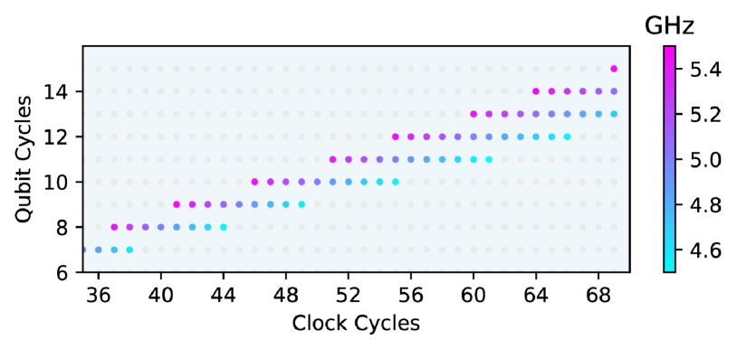
To avoid these phase errors, the key is to tune the qubit frequency such that the total gate time corresponds to both an integer number of clock cycles and an integer number of qubit cycles , so that . This relation translates into the following frequency matching condition:
| (21) |
where is the angular frequency of the clock. We can use Fig. 3 to find frequencies that satisfy Eq. (21). In this diagram, each grid point represents a qubit frequency (shown in color scale) determined from the above matching condition. Again, we consider a 25 GHz SFQ clock; for a small range of frequencies around each of the “magic” qubit operating points given by Eq. (21), accurate qubit control is possible.
From frequency-matching relation (21), it is clear that longer gate times will permit high-fidelity control of a larger number of distinct qubit frequencies. However, the number of register bits needed to describe the pulse sequence can be drastically reduced by the repeated streaming of high-fidelity subsequences. This strategy leads to compact registers that are efficient to implement in hardware, and it provides a desirable periodic suppression of leakage as a side effect, as we discuss below in Sec. III.4.
In more detail, the length of the subsequence is a trade-off between the number of register bits and the performance of the subsequence. If the length is too short, the search space will be too restricted to contain high-fidelity subsequences, and the number of qubit frequencies we can control will be decreased (see Fig. 3). In our simulations, we find a good balance for subsequences consisting of bits. The number of subsequence repetitions, and thus the overall length of the gate, is set by the size of the coherent rotation imparted to the qubit per SFQ pulse. The relationship between gate time and tip angle is , and it is tempting to reduce the gate time by increasing ; for large tip angle, however, errors that are second order in will become significant. We find that is optimal, corresponding to a reasonable coupling capacitance from the SFQ driver circuit to the qubit island of order 100 aF for typical transmon parameters. For the simulations described here, we target gate time around ns.
With this frequency matching condition and approach to hardware optimization, we can immediately construct some basic subsequences as follows. Given the number of clock cycles and qubit cycles in a subsequence, for each clock cycle we apply an SFQ pulse on a given clock edge provided the pulse induces a rotation in the positive -direction. We then repeat the subsequence an appropriate number of times to achieve the target rotation. Explicitly, we deliver an SFQ pulse to the qubit on the clock edge of the subsequence provided the following condition is fulfilled:
| (22) |
This class of subsequences is expected to yield reasonably high fidelity because it has a palindrome structure, which implies that pulses are delivered to the qubit as symmetric pairs. For example, the first and last pulses form the pair ; the second and penultimate pulses form the pair , etc. In general, the sequence contains a pair for each between and that satisfies (22).
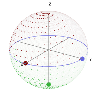
As an example, we simulate a sequence built from 10 repetitions of a basic subsequence using and ; a plot of the qubit trajectory on the Bloch sphere is shown in Fig. 4 for a GHz qubit initialized along the (green), (purple), and (red) directions. Here, the tip angle is chosen to achieve the rotation in 390 clock steps. Assuming a qubit anharmonicity of 250 MHz and a 25 GHz SFQ clock frequency, this sequence achieves fidelity of in under ns. Although this scheme for constructing basic subsequences demonstrates the possibility of controlling multiple qubit frequencies using a single global clock, it is by no means optimal, as the achieved fidelity is rather modest. The dominant source of infidelity is leakage from the computational subspace. In the following subsection, we describe an approach to suppress this leakage.
III.3 Leakage Suppression
At the core of SCALLOPS is the optimization algorithm that eliminates leakage from the computational subspace. Starting with a basic subsequence of the type described in Sec. III.2, we need to flip bits in order to suppress leakage while preserving the target rotation in the qubit subspace. The major difficulty in subsequence optimization is that bit flips that reduce leakage will generally disrupt the rotation in the qubit subspace. This problem is analogous to solving a Rubik’s cube: when the cube mismatched at the top layer, a naive set of operations to complete the top layer will generally disrupt the other layers that are already matched. This difficulty can be circumvented by using a sequence of operations whose net effect is felt only at the top layer. We can solve the qubit control problem analogously: the corresponding sequence of operations is to flip a symmetric pair of bits in the subsequence and to scale the tip angle to preserve rotation in the qubit subspace. While this latter step might seem dubious, given that is fixed by the geometric coupling of the SFQ driver to the qubit, we will show that for a given qubit frequency satisfying the matching condition Eq. (21) there exists a high density of high-fidelity subsequences in the space of tip angles . Our strategy will be to allow to vary as we search for a cluster of high-fidelity, low-leakage subsequences. Then we will select those subsequences that achieve highest fidelity for the specific value of dictated by the available hardware.
More formally, we can describe this method in terms of a subsequence graph , where the vertices represent individual SFQ subsequences with their optimal tip angles and the connections link subsequences that are separated by a single symmetric pair of bit flips. Explicitly,
-
•
Each vertex is described by a subsequence bit pattern and its optimal tip angle .
-
•
Each connection links subsequences that differ by a single symmetric pair .
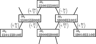
We define and in this way with the goal of separating control in the qubit subspace from leakage elimination: navigation through the subsequence graph preserves rotation in the qubit subspace, but movement from vertex to vertex can change leakage out of the computational subspace substantially, as one can see from Eq. (18). A trivial example of the subsequence graph is shown in Fig. 5.
With this definition of the subsequence graph , we describe a simple procedure to find high-fidelity subsequences. We first construct a basic subsequence as defined in Sec. III.2. This subsequence serves as the entrance point to the subsequence graph. We then explore all vertices adjacent to and greedily move to the vertex with the highest fidelity. We repeat this greedy move until we reach a local fidelity maximum. This typically takes only 5-10 steps. In general, 5-8 repetitions of such high-fidelity subsequences will yield gates with fidelity greater than in a total sequence time under ns.
The subsequences generated by the algorithm described above are not yet sufficient for experimental implementation because we have allowed the tip angle per SFQ pulse to vary during our search. In practice, the tip angle is determined by the coupling capacitance of the SFQ driver to the transmon qubit and cannot be exquisitely controlled during fabrication, or varied in situ following fabrication.
The solution to the problem is to explore a larger region of the subsequence graph and to identify a large ensemble of high-fidelity candidate subsequences corresponding to a range of optimal tip angle . For each of these subsequences, high-fidelity rotations (say, infidelity under ) are achieved over a range of , so that it is straightforward to identify from this ensemble specific subsequences that yield high fidelity for a fixed . More specifically, we ignore all vertices with fidelity lower than and perform a standard breadth-first search to traverse the remaining vertices of the graph, leading to a set of characterized subsequences which we call the subsequence neighborhood.
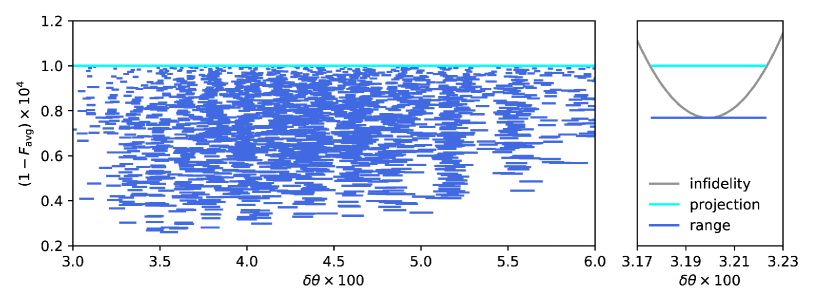
In Fig. 6 we plot the infidelities achieved versus the tip angle for a subsequence neighborhood associated with a GHz qubit. For each individual subsequence in the neighborhood, high fidelity is reached for only a small range of tip angles around the optimal value. However, given a fixed value of , numerous subsequences are available that achieve gate fidelity well beyond the target of 99.99%. This is true for SFQ tip angle spanning a broad range from to , which is more than enough to accommodate any inaccuracy in the design of the coupling capacitance between the SFQ driver and the transmon.
III.4 Sequence Verification
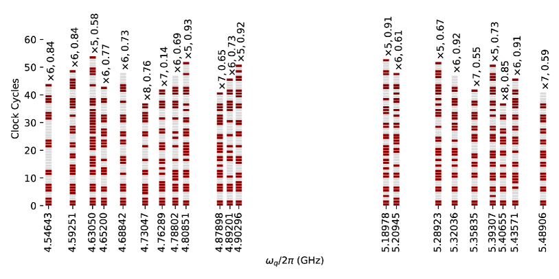
We have performed the above-described neighborhood search for different frequencies satisfying the matching condition given by Eq. (21). The result is shown in Fig. 7. While a 3-level model of the transmon was used to derive the sequences, the presented fidelities were calculated for a model incorporating 7 energy levels.
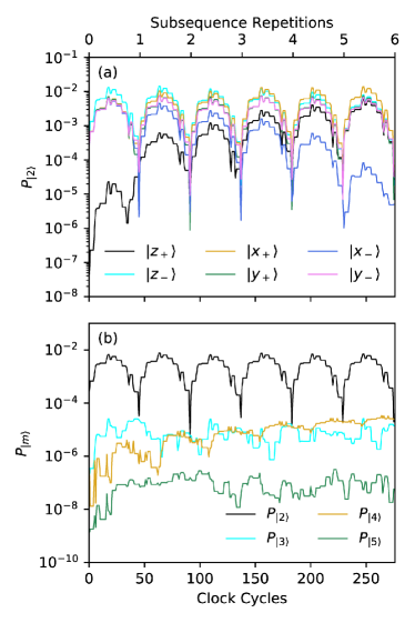
In Fig. 8, we examine leakage into the noncomputational states , , , and for the SCALLOP sequence corresponding to the 4.89201 GHz qubit. We observe that the dominant leakage into state is roughly bounded at for initial qubit states spanning the cardinal points on the Bloch sphere. Moreover, as the qubit state approaches , we see that leakage into is particularly low, as demonstrated in the curves corresponding to initial states and . While the population of state can approach toward the middle of the subsequence, the population always drops below at the completion of each subsequence repetition, as the subsequences are explicitly constructed to minimize leakage from the qubit subspace. The population of states and is well below throughout, while states and higher have negligible populations.
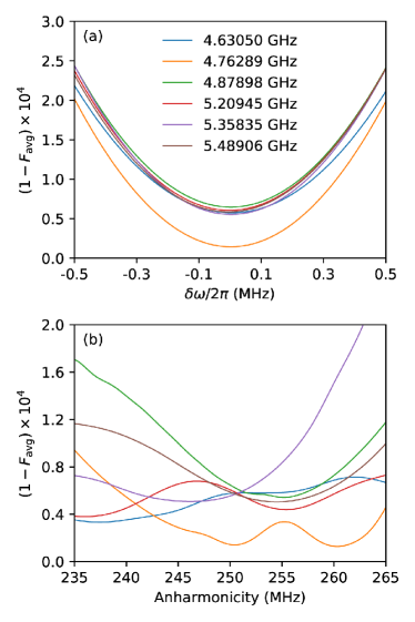
Finally, in Fig. 9 we simulate the effect of qubit parameter variation on SCALLOP gate fidelity. Error from frequency drift can be modeled as an ideal gate followed by a small precession: . From Eq. (13), the infidelity of this gate is then approximately . For gate fidelity to degrade by , the qubit frequency drift must reach about 300 kHz, given a gate time of 12 ns. This naive estimate is in qualitative agreement with the full simulation results in Fig. 9a; note that based on the above argument, we expect microwave-based qubit gates to display similar sensitivity to qubit frequency drift. In Fig. 9b we see that SCALLOP gate fidelity is relatively insensitive to variation in qubit anharmonicity. In a practical system, the anharmonicity of each qubit would be calibrated upon system bringup. As anharmonicity is set by the transmon charging energy, it is not expected to fluctuate in time.
IV CONCLUSION
We have performed numerical simulations to demonstrate coherent qubit control across multiple frequencies using irradiation with classical bits derived from the SFQ logic family. Using a single global clock at 25 GHz to stream pulses from compact registers consisting of 35-55 bits, we achieve gate fidelity better than across qubit frequencies spanning the range from 4.5 to 5.5 GHz. The control subsequences are readily amenable to storage in compact SFQ-based shift registers, as outlined in McDermott et al. (2018). We have described an intuitive, efficient method for the derivation of high-fidelity SFQ-based pulse sequences that is readily adapted to arbitrary single-qubit gates. The SCALLOPS method is robust in the sense that large imprecision in the tip angle per SFQ pulse is readily accommodated by appropriate variation in the subsequence bitstream. The control approach is immune to wiring parasitics and offers the possibility for tight integration of a large-scale quantum array with a proximal classical coprocessor for the purposes of reducing system footprint, wiring heatload, and control latency.
Acknowledgements.
This work was supported by the NSF under Grant QIS-1720304.References
- Feynman (1982) R. P. Feynman, Int. J. Theor. Phys. 21, 467 (1982).
- Clarke and Wilhelm (2008) J. Clarke and F. K. Wilhelm, Nature 453, 1031 (2008).
- Fowler et al. (2012) A. G. Fowler, M. Mariantoni, J. M. Martinis, and A. N. Cleland, Phys. Rev. A 86, 032324 (2012).
- Barends et al. (2014) R. Barends, J. Kelly, A. Veitia, A. Megrant, A. G. Fowler, B. Campbell, Y. Chen, Z. Chen, B. Chiaro, A. Dunsworth, I.-C. Hoi, E. Jeffrey, C. Neill, P. J. J. O’Malley, J. Mutus, C. Quintana, P. Roushan, D. Sank, J. Wenner, T. C. White, A. N. Korotkov, A. N. Cleland, and J. M. Martinis, Phys. Rev. A 90, 030303 (2014).
- Motzoi et al. (2009) F. Motzoi, J. M. Gambetta, P. Rebentrost, and F. K. Wilhelm, Phys. Rev. Lett. 103, 110501 (2009).
- Lucero et al. (2010) E. Lucero, J. Kelly, R. C. Bialczak, M. Lenander, M. Mariantoni, M. Neeley, A. D. O’Connell, D. Sank, H. Wang, M. Weides, J. Wenner, T. Yamamoto, A. N. Cleland, and J. M. Martinis, Phys. Rev. A 82, 042339 (2010).
- Chow et al. (2010) J. M. Chow, L. DiCarlo, J. M. Gambetta, F. Motzoi, L. Frunzio, S. M. Girvin, and R. J. Schoelkopf, Phys. Rev. A 82, 040305 (2010).
- Chen et al. (2016) Z. Chen, J. Kelly, C. Quintana, R. Barends, B. Campbell, Y. Chen, B. Chiaro, A. Dunsworth, A. G. Fowler, E. Lucero, E. Jeffrey, A. Megrant, J. Mutus, M. Neeley, C. Neill, P. J. J. O’Malley, P. Roushan, D. Sank, A. Vainsencher, J. Wenner, T. C. White, A. N. Korotkov, and J. M. Martinis, Phys. Rev. Lett. 116, 020501 (2016).
- Asaad et al. (2016) S. Asaad, C. Dickel, N. K. Langford, S. Poletto, A. Bruno, M. A. Rol, D. Deurloo, and L. DiCarlo, npj Quantum Inf. 2, 16029 (2016).
- Versluis et al. (2017) R. Versluis, S. Poletto, N. Khammassi, B. Tarasinski, N. Haider, D. J. Michalak, A. Bruno, K. Bertels, and L. DiCarlo, Phys. Rev. Applied 8, 034021 (2017).
- Vijay et al. (2012) R. Vijay, C. Macklin, D. H. Slichter, S. J. Weber, K. W. Murch, R. Naik, A. N. Korotkov, and I. Siddiqi, Nature 490, 77 (2012).
- Campagne-Ibarcq et al. (2013) P. Campagne-Ibarcq, E. Flurin, N. Roch, D. Darson, P. Morfin, M. Mirrahimi, M. H. Devoret, F. Mallet, and B. Huard, Phys. Rev. X 3, 021008 (2013).
- Ristè et al. (2012) D. Ristè, C. C. Bultink, K. W. Lehnert, and L. DiCarlo, Phys. Rev. Lett. 109, 240502 (2012).
- Likharev and Semenov (1991) K. K. Likharev and V. K. Semenov, IEEE Trans. Appl. Supercond. 1, 3 (1991).
- McDermott and Vavilov (2014) R. McDermott and M. G. Vavilov, Phys. Rev. Applied 2, 014007 (2014).
- Leonard et al. (2019) E. Leonard, M. A. Beck, J. Nelson, B. G. Christensen, T. Thorbeck, C. Howington, A. Opremcak, I. V. Pechenezhskiy, K. Dodge, N. P. Dupuis, M. D. Hutchings, J. Ku, F. Schlenker, J. Suttle, C. Wilen, S. Zhu, M. G. Vavilov, B. L. T. Plourde, and R. McDermott, Phys. Rev. Applied 11, 014009 (2019).
- McDermott et al. (2018) R. McDermott, M. G. Vavilov, B. L. T. Plourde, F. K. Wilhelm, P. J. Liebermann, O. A. Mukhanov, and T. A. Ohki, Quantum Sci. Technol. 3, 024004 (2018).
- Liebermann and Wilhelm (2016) P. J. Liebermann and F. K. Wilhelm, Phys. Rev. Applied 6, 024022 (2016).
- Koch et al. (2007) J. Koch, T. M. Yu, J. Gambetta, A. A. Houck, D. I. Schuster, J. Majer, A. Blais, M. H. Devoret, S. M. Girvin, and R. J. Schoelkopf, Phys. Rev. A 76, 042319 (2007).
- Bowdrey et al. (2002) M. D. Bowdrey, D. K. L. Oi, A. J. Short, K. Banaszek, and J. A. Jones, Phys. Lett. A 294, 258 (2002).
- Steffen et al. (2003) M. Steffen, J. M. Martinis, and I. L. Chuang, Phys. Rev. B 68, 224518 (2003).