Minimizing the Signaling Overhead and Latency based on Users’ Mobility Patterns
Abstract
We demonstrate a distributed and a centralized 4G/5G compliant approach to minimize signaling and latency related to user mobility in cellular networks. This is crucial due to the densification of networks and the additional signaling introduced by the new 5G service based architecture. By exploiting standardized protocols, our solutions dynamically reorganize the association between nodes in Radio Access Network (RAN) and the core. We validated the proposed approaches using real user mobility datasets. Our results show that both our distributed and centralized solutions significantly reduce the signaling between core and RAN compared to the traditional approach based on geographical proximity. As a result, both approaches significantly reduce the average handover procedure processing time. Moreover, by relying on locally available information, the distributed approach can quickly adapt to changes in the user movement patterns as they happen.
I Introduction
Due to the increasing densification of cellular networks and mobile devices (e.g. Internet of Things devices for logistics and supply chain management), the number of handovers will significantly grow. Mobility management optimization based on User Equipment (UE) mobility patterns recognition has been identified as one of the key issues by the 3rd Generation Partnership Project (3GPP) [1]. Not all handovers come with the same cost in terms of signaling to the core network and therefore in terms of latency. One of the key factors to determine the signalling overhead associated to handover procedures is the association between nodes in the Radio Access Network (RAN) and nodes (e.g. Mobility Management Entity (MME) in the case of 4G), functions (e.g. Access and Mobility Function (AMF) in the case of 5G), and Location Regions (e.g. Tracking Area (TA), Registration Area, TA List) in the core network. The focus of this work is on this RAN-to-core association for 4G, i.e. RAN-to-MME association, and 5G, i.e. RAN-to-AMF association. We focus on both 4G and 5G for two reasons: the RAN-to-core association is similar in both architectures, and the transition from 4G to 5G will be evolutionary rather than revolutionary meaning that both technologies will coexist for a time [2].
In the remainder of this paper we refer to handovers requiring an MME/AMF reallocation as inter-region handovers. This is the most inefficient type of handover in terms of delay and number of exchanged signaling messages. In fact, inter-region handovers require on average 50% more signaling messages compared to the intra-region ones, i.e. handovers that do not result in a change of the MME/AMF [3]. That results in higher latency of the inter-region handover procedures compared to the intra-region handovers [4]. In this paper we propose an approach to reorganize nodes in the network so that the number of handovers requiring an MME reallocation in the case of 4G or an AMF reallocation in the case of 5G is minimized. Our smart design of the handover regions based on UE mobility information can be implemented in a distributed or centralized manner. The distributed node re-configuration relies on existing protocol messages and network management systems [5, 6]. The centralized mechanism also relies on the same information, but due to the lack of requirements for these messages to be forwarded to the Operations Support System (OSS), it has to be implemented as a passive probe in the core network. The computational complexity of the distributed solution is as compared to centralized one that is an NP-hard problem. Both approaches balance the load between the MME/AMF instances and are independent of the specific handover mechanisms implemented in the network. Moreover, they successfully adjust to both, the up- and down-scaling of resources in the core network (e.g. new AMF instance) and the changes in UE mobility patterns in the RAN.
II Related Works
In the literature, a number of approaches have been proposed for autonomic network optimization. The authors of [7, 8, 9, 10] highlight the existing and anticipate the upcoming problems related to signaling traffic, which will overload the AMF instances. In addition, authors of [11] call attention to issues related to quality of service and high mobility. All of them agree that the flexibility of Virtualized Network Functions and intelligent resource allocation will be the key ingredient to solve these problems. The work in [7], focuses on the exploitation of the prediction of user behavior to improve post-handover procedures. The authors of [8, 9] show preliminary results proving that traffic forecasting techniques based on machine learning outperform the threshold-based solutions for dynamic up- and down-scaling of network resources. Similarly, in [10], the authors propose a control theory based algorithm for autonomic up- and down-scaling of AMFs in the network. Our work also focuses on the optimization of the signaling overhead and the control plane latency, but instead of forecasting the traffic load or performing the up- and down-scaling of resources, we exploit information on user mobility to perform intelligent re-configurations of the network nodes.
In [12] a mechanism to minimize the number of Serving Gateway (SGW) relocations is proposed. While MME relocation is also mentioned, the authors focus on the SGW. They propose the introduction of a Service Area for idle users, which is a subset of the Service Area of each SGW. Although the results show a decrease of the number of SGW relocations for users in active mode, the mechanism to determine the idle-mode service areas is not provided and the implications in terms of existing standards are not discussed. In [13] a centralized heuristic mechanism to deploy network functions so as to minimize the number of SGW relocations is proposed. The minimization of MME relocations is only mentioned as a possible application. However, the proposed solution relies on a greedy algorithm with high computational complexity (i.e. ) that does not assure a significant improvement in terms of SGW relocations. Moreover, the authors do not discuss the improvements compared to the existing industry standard techniques for network planning and they do not provide details about the integration of their solution with existing or future networks. In contrast, our solution exploits standardized protocols and mechanisms, which will facilitate its adoption.
Another approach in literature for inter-region handover optimization relies on a new architecture, proposed in [14]. The authors propose a recursive hierarchical algorithm to minimize the number of inter-region handovers in [15]. In contrast, the solution we propose is designed to work within existing (4G) and emerging (5G) mobile networks so as to maximize technology adoption. Specific solutions for handover latency reduction have been proposed in the case of femto cells [16, 17]. These two patents detail an optimized intra-HeNB GW (Home eNodeB Gateway) handover mechanism that reduces signaling to and from an MME. While our approach also aims at reducing the signaling to and from the MME, our network-wide approach is not restricted to the specific femto cell case and we take into account users’ mobility when optimizing the nodes configuration. In [18, 19], the inventors detail a mechanism to re-assign Base Stations to MMEs so as to balance the load of the MMEs. Our solution, while also considering the load, re-configures the nodes based on the user movements.
Our solution is a general approach to the node to x-area association, where x can be a handover region, a TA or a set of TAs. Therefore, closely related to the question addressed by our solution is the autonomous configuration of TAs and TA Lists. Several solutions aiming at minimizing the signaling overhead caused by the periodic TA updates and paging have been developed in the research literature [20] or patented [21, 22]. The approaches in [20, 21, 22] are centralized and require information that does not exist in the network (e.g. the UE average speed, the average number of UE per cell). Additionally, the authors do not provide implementation details in terms of data collection, and reconfiguration of the nodes. In contrast, our approach relies only on information available in the network allowing an easy integration with the existing 4G and future 5G systems.
III Handover Region Optimization
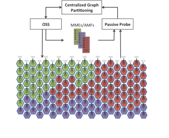
It is possible to minimize the number of inter-region handovers by dynamically re-configuring the association between BSs and nodes in the core, i.e. by grouping the BSs that exchange more users into the same handover region. In this Section we present two alternatives to the handover region optimization problem. We first start with a centralized optimal formulation. Due to the delay and the computational complexity of the Centralized Graph Partitioning (CGP) approach, we also propose a distributed approach for the optimization. Finally, we show that the proposed distributed solution can be implemented by leveraging information already collected and exchanged within the network. While the centralized mechanism also relies on the same information, current standards do not require that information to be forwarded to the OSS. This means that the centralized mechanism would be implemented as a passive probe in the core network. Hence, the optimal centralized solution could be deployed after the conditions in the network (UE traffic pattern) have changed.
III-A Centralized Graph Partitioning Approach
Re-configuring RAN-to-core nodes association can be formulated as a -way Graph Partitioning Problem (GPP) on an undirected weighted graph that represents BSs as the set of vertices and the occurrence of handovers between BSs as the set of edges . The weight is the normalized number of handovers that occurred between nodes and :
| (1) |
where is the number of handovers between nodes and , and are the maximum and minimum number of handovers that occurred between any two nodes in the graph. For each edge let us introduce a binary variable , which is equal to iff and belong to two handover regions, i.e. to two MMEs/AMFs. We also define a binary variable for each vertex and each region , which is the set of all available MMEs/AMFs. is equal to iff node belongs to handover region . We denote the traffic load of each vertex with and the load threshold of region with . The RAN-to-core nodes association can be formulated as an integer linear programming problem:
| minimize | |||||
| subject to | |||||
| (2) | |||||
Due to the NP-hard nature of the -way GPP, we rely on the metis library to solve (III-A)111http://glaros.dtc.umn.edu/gkhome/views/metis. The centralized approach involves multiple stages: handover data collection at the BSs; transferring the data to a centralized node in the core network; running the optimization; and transferring signaling messages in order to perform the re-configuration of the network (see Figure 1a). Hence, this approach results in an increased delay related to the network re-configuration.
III-B Distributed Self-Organization Approach
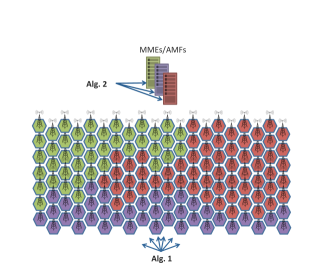
We now present a Distributed Self-Organized (DSO) solution to the problem of handover region optimization. The proposed approach consists of two main components, one running on the RAN nodes and the other one on virtual instances of core nodes (e.g. MMEs/AMFs) (see Figure 1b). The computational complexity of both components is .
The component running on the RAN nodes is formalized in Alg. 1. It relies on handover counters already available at the BSs (e.g. number of handovers, source handover MME). The initial assignment of a BS is chosen based on the majority of its neighbors. The optimization process is triggered whenever a handover occurs or in case an MME/AMF sends a reassignment request. In case of a handover, the BS updates its counters and the algorithm calculates the energy of attraction towards all available MMEs/AMFs. The energy of attraction of node towards the -th MME/AMF is calculated as:
| (3) |
where is the number of handover requests that arrived at node from nodes that are assigned to the -th MME/AMF. Therefore, the energy of attraction towards an MME/AMF is the ratio between the number of handover requests originating from this MME/AMF and the total number of handover requests that arrived on the observed node. Once the counters are updated and the energy of attraction is calculated, the BS decides whether to change its MMEs/AMFs assignment based on the energy of attraction. It should be noted that the DSO enables overlapping handover regions, i.e. a BS can be connected to multiple MMEs/AMFs. The ping pong threshold restricts the BS from constantly changing its assigned MMEs/AMFs. Once a BS changes its assignment, the counters are reset to default values and the adaptation process restarts. The reset to the default values can be a hard reset, which resets the values to zero, or a soft reset, that sets the values of the counters by using a moving average. In case an MME/AMF requests a reassignment of the BS to another MME/AMF, the BS attempts to get assigned to the next best (based on the energy of attraction) available MME/AMF.
The second component runs on a virtual instance of the MME/AMF and is formalized in Alg. 2. The MME/AMF waits for a request from a node that wants to get assigned to it. If the combined load of the MME/AMF and the load coming from the node requesting the assignment is lower than a threshold (), the request is accepted. In case the total load is greater than the threshold, the assignment can be accepted or rejected depending on the energy of attraction of the cell that is requesting the assignment. In particular, the assignment request is accepted only if among the cells currently attached to the MME/AMF there exists one with lower energy of attraction which, if removed, would free up enough resources to manage the requesting cell. If multiple such cells exist, the one with the lowest energy of attraction is selected, informed to change its assignment, and removed from the list of cells assigned to the current MME/AMF.
III-C Integration with Network Protocols
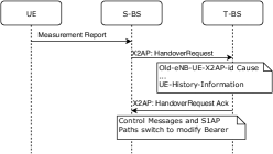
It is important to highlight that the approaches described in Section III-A and III-B have been designed to rely solely on information that is available through already existing signaling messages, removing the need for additional signaling and at the same time simplifying the integration with the existing architecture. The information of interest to the CGP and DSO is the type of handover, the number of handovers and the source MME from which the handover originated. To explain this let us consider the procedures used to perform the two different types of handover (inter and intra-region). In 4G, the intra-region handovers are X2 and S1 without MME reallocation. On the other hand, the inter-region handover procedure is the S1 with MME reallocation. Similarly, in 5G, the equivalent of the intra-region handover procedures are Xn and N2 without AMF reallocation; and the equivalent of the inter-region handover procedure is N2 with AMF reallocation.
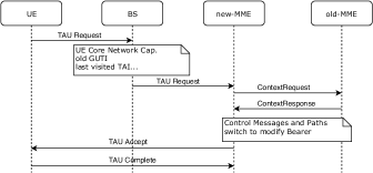

As shown in Fig. 2, the X2 handover procedure assumes direct communication between the involved nodes. The HandoverRequest message contains a field reserved for the UE History Information, which contains information about the last visited cells by the UE [5]. This information is used to determine where the handover is coming from. Since the request is sent through the X2 link between two nodes, the handover type is obviously intra-region, i.e. the source MME is equal to the destination MME. This means that all counters can be updated appropriately (both the total number of handovers and the number of intra-region handovers are increased by ).
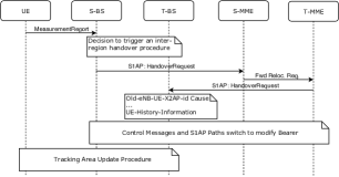
Fig. 3 shows the procedure that is used to perform a handover between nodes associated with different MMEs. The initial HandoverRequest message contains a field that transfers the information from the source to the target node (TargeteNB-ToSourceeNB-TransparentContainer), which contains the UE History Information similarly to the previous case [23]. In case of an inter-region handover, we have to determine the source MME as well in order to update all counters needed to calculate the energy of attraction in (3). Considering that an MME covers whole TAs, the inter-region handover includes a Tracking Area Update (TAU) as well (the last part of the handover procedure shown in Fig. 3), and in case of an intra-region S1 handover (an S1 handover without MME reallocation) the TAU is not required, which indicates to our algorithm that the source and target handover region are the same. As shown in Fig. 4, the first message that is sent from the UE to the BS is the TAU Request, which contains information like UE Core Network Capability, old Globally Unique Temporary UE Identity (GUTI), last visited TA, etc. [3]. The old GUTI is the identifier of interest to our algorithm, because it consists of two main components, namely the Globally Unique MME Identifier (GUMMEI) and the MME Temporary Mobile Subscriber Identity (M-TMSI). Since the GUMMEI uniquely identifies the MME which has allocated the GUTI, we have all the information needed to update all counters to calculate (3).
IV Performance evaluation
In this section, we compare the performance of the DSO approach detailed in Section III-B, the CGP approach described in Section III-A, and the traditional static approach which groups BSs into regions based on their location. We rely on Agent Based Modeling, a computational model suitable for simulations of heterogeneous and self-organizing systems, to model the interactions between the BSs and the instances of MMEs/AMFs whose behavior is formalized in Alg. 1 and 2. For our simulations we draw on the dataset in [24], which provides BS locations worldwide, and the dataset in [25], which provides information about the movements of taxis in the San Francisco Bay Area, USA. We combine the two datasets to simulate the handover occurrences between BSs. In the considered area BSs are active. In our simulations we followed the 3GPP recommendations [26] for the BS coverage - m coverage radius. We analyze the taxi movements for two days in order to capture the impact of the changes in user mobility patterns. We assume that the load of each BS is the same — , and the load threshold of each region is . Hence, the partitioning defined with (III-A) results in an equal number of nodes in each partition. The ping point threshold in Alg. 1 is , while in Alg. 2.
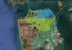
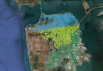
Fig. 5 zooms in on the grouping of BSs into handover regions in San Francisco. The BSs are grouped into four regions shown in green, blue, yellow and brown. Each region contains approximately the same number of BSs. The map on the left in Fig. 5 shows the geographical approach to group the BSs into four regions with a balanced number of BSs. The map in the middle shows the grouping of the BSs resulting from the CGP. Instead of relying on geographical proximity of BSs, the RAN-to-core node association in this case is performed based on the user movement information collected during Day . The map on the right in Fig. 5 shows the RAN-to-core node associations at 9PM of the same day resulting from the DSO approach. The DSO approach adapts over time: the BSs constantly monitor their counters and make decisions about their association. The difference between the three maps is conspicuous, and it shows that the spatial proximity of BSs does not necessarily lead to a large exchange of users between them. For example, nearby BSs do not exchange a lot of users if their coverage areas overlap or if due to the terrain configuration it is impossible to move between them.
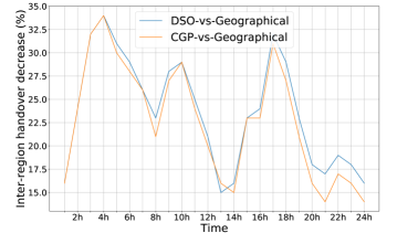
The map shown in the middle in Fig. 5 is the ex post optimal static association (CGP) of nodes for the whole Day under consideration, i.e. the information over the whole Day is gathered and the best possible configuration for that period is computed. This might not be the best association at every point in time during the day since the number of handovers between BSs changes over time, and the weights in the objective in (III-A) are the normalized total number of handovers between BSs over a period of time (in this case Day ). Since the CGP requires information to be centrally collected, although theoretically possible, it is unlikely that the CGP could be run over a shorter period. Let us now take a closer look at how the share of inter-region handovers changes over time. Fig. 6 shows the percentage of inter-region handovers during the Day of the DSO and CGP (ex post) with respect to the geographical clustering. As shown in Fig. 6 the decrease of inter-region handovers in case of CGP is at least and at some point goes up to %. Perhaps more importantly, the DSO either performs as well as CGP, or it outperforms it. This is due to its adaptive nature, which acts based on locally available information making the readjustments agile.
| Geographical | CGP |
|
|||
| Geographical | / | /- | %/% | ||
| CGP | %/% | / | %/% | ||
| DSO | 34.2%/% | %/ | / |
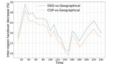
Fig. 7 shows the hourly decrease of inter-region handovers during Day . The performance of the CGP approach corresponds to the same RAN-to-core node association used in Fig. 6. This is a more fair comparison between the CGP and the DSO approach, in that the RAN-to-core node association is computed based on historical data and then used in the network. In this case the gain achieved with the CGP approach is evidently lower compared to the DSO approach. Both approaches - even the CGP one relying on outdated information - significantly outperform the geographical association.
Now, let us examine the overall impact on the number of inter-region handovers in the network. Table I shows the reduction of inter-region handovers for Day (blue) and Day (red). Both the CGP and DSO perform significantly better compared to the geographical approach, with a minimum gain of . The gain of the DSO approach compared to the CGP one is in Day , which is more than two times higher compared to the gain during Day . This is due to changes in the user movement patterns: a static approach to optimizing the RAN-to-core nodes association is suboptimal.
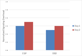
We also study the signaling overhead related to the handover procedures. As previously mentioned in Section I, inter-region handovers require a significantly larger number of signaling messages compared to intra-region handovers. Therefore, by minimizing the number of inter-region handovers, we minimize the overall network signaling overhead. Figure 8 compares the normalized signaling overhead related to the execution of handovers for the CGP and DSO approaches. As shown in Figure 8, both optimization techniques, i.e. the CGP and the DSO, clearly outperform and minimize the signaling overhead compared to the traditional geographical clustering approach.
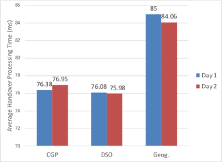
The reduction related to the signaling overhead affects the average handover procedure processing time. According to [27, 28] the average handover procedure processing time also depends on the type of handover. The processing of intra-region handovers is estimated to ms, whereas the processing time of inter-region handovers is estimated to be in the range from ms to ms. Figure 9 shows the comparison between the average handover procedure processing time for the CGP, DSO and geographical approach. As shown in Figure 9, the CGP and the DSO algorithms significantly reduce the average handover procedure processing time. The results presented in Figure 8 and Figure 9 clearly highlight the benefits from the handover region optimization techniques presented in this paper. They also prove that the delay and signaling overhead related to handover procedures can be reduced without the need to change the procedures themselves, but rather by reconfiguring the association between the RAN nodes and the nodes in the core network.
V Conclusions
We proposed a method to reorganize nodes in the network so that the number of handovers requiring an MME/AMF reallocation is minimized. We presented a distributed (DSO) and a centralized approach (CGP). In the case of the centralized approach, the novelty consists in formalizing the handover regions optimization as a graph partitioning optimization problem that only relies on information already used within 4G and 5G networks. In the case of the distributed approach, the additional novelty consists in proposing a new method that optimizes the handover regions in a distributed manner and only relies on local information already available to each node (base stations and MME/AMF) in a 4G and 5G network. Both approaches outperform the traditional geographic clustering of BSs and significantly reduce the average handover procedure processing time. We validated the proposed approaches using real user mobility datasets. By relying on distributed decision making, the DSO can adapt to the changes in the user movement patterns as they happen, and outperforms CGP removing also the need for collecting the information at the OSS. Future work will focus on modelling overlapping handover regions in the centralized approach (which is currently only included in DSO) and examine the implications of dynamic up- and down- scaling of MMEs/AMFs.
- 3GPP
- 3rd Generation Partnership Project
- BSs
- Base Stations
- BS
- Base Station
- TAs
- Tracking Areas
- TAL
- Tracking Area List
- TA
- Tracking Area
- ABM
- Agent-Based Modeling
- EPC
- Evolved Packet Core
- MME
- Mobility Management Entity
- SGW
- Serving Gateway
- PGW
- Packet Gateway
- HSS
- Home Subscriber Server
- M2M
- Machine to Machine
- 5G
- Fifth Generation
- SDN
- Software Defined Networking
- NFV
- Network Function Virtualization
- VNF
- Virtualized Network Function
- IoT
- Internet of Things
- KPI
- Key Performance Indicator
- GSM
- Global System for Mobile Communications
- UMTS
- Universal Mobile Telecommunications System
- LTE
- Long Term Evolution
- C-RAN
- Cloud Radio Access Network
- FAP
- Femtocell Access Point
- UE
- User Equipment
- 3GPP
- 3rd Generation Partnership Project
- MB-ICIC
- Mobility-Based Inter-Cell Interference Coordination
- MAC
- Medium Access Control
- RACH
- Random-Access Channel
- RAN
- Radio Access Network
- PCRF
- Policy control and Charging Rules Function
- TAU
- Tracking Area Update
- SBA
- Service Based Architecture
- AMF
- Access and Mobility Function
- UPF
- User Plane Function
- SMF
- Session Management Function
- PCF
- Policy Control Function
- GPP
- Graph Partitioning Problem
- GCP
- Graph Coloring Problem
- ILP
- Integer Linear Programming
- CGP
- Centralized Graph Partitioning
- DSO
- Distributed Self-Organized
- OSS
- Operations Support System
- GUTI
- Globally Unique Temporary UE Identity
- GUMMEI
- Globally Unique MME Identifier
- M-TMSI
- MME Temporary Mobile Subscriber Identity
References
- [1] 3GPP, “3GPP TR 23.791 Version 1.0.0 Release 16,” Tech. Rep., 2018.
- [2] M. Patzold, “5G Readiness on the Horizon [Mobile Radio],” IEEE Vehicular Technology Magazine, vol. 13, no. 1, pp. 6–13, 2018.
- [3] 3GPP, “3GPP TS 23.401 Version 14.3.0 Release 14,” Tech. Rep., 2017.
- [4] ——, “3GPP TS 36.133 Version 14.3.0 Release 14,” Tech. Rep., 2017.
- [5] ——, “3GPP TS 36.423 Version 12.3.0 Release 12,” Tech. Rep., 2014.
- [6] ——, “TS 28.533 Version 15.0.0 Release 15,” Tech. Rep., 2018.
- [7] P. Sebastian and M. A. Khan, “Anticipatory User Plane Management for 5G,” IEEE International Symposium on Cloud and Service Computing (SC2), pp. 9–15, 2018.
- [8] I. Alawe, A. Ksentini, Y. Hadjadj-Aoul, and P. Bertin, “Improving Traffic Forecasting for 5G Core Network Scalability: A Machine Learning Approach,” IEEE Network, vol. 32, no. 6, pp. 42–49, 2018.
- [9] I. Alawe, Y. Hadjadj-Aoul, A. Ksentini, P. Bertin, C. Viho, and D. Darche, “Smart Scaling of the 5G Core Network: An RNN-based Approach,” IEEE Global Communications Conference (GLOBECOM), pp. 1–6, 2018.
- [10] I. Alawe, Y. Hadjadj-Aoul, A. Ksentini, P. Bertin, and D. Darche, “On the scalability of 5G Core network: the AMF case,” IEEE Annual Consumer Communications & Networking Conference (CCNC), pp. 1–6, 2018.
- [11] A. H. Sodhro, M. S. Obaidat, Q. H. Abbasi, P. Pace, S. Pirbhulal, A.-U.-H. Yasar, G. Fortino, M. A. Imran, and M. Qaraqe, “Quality of Service Optimization in an IoT-Driven Intelligent Transportation System,” IEEE Wireless Communications, vol. 26, no. 6, pp. 10–17, 2019.
- [12] A. Kunz et al., “On Minimizing Serving GW/MME Relocations in LTE,” International Wireless Communications and Mobile Computing Conference, pp. 960–965, 2010.
- [13] T. Taleb and A. Ksentini, “Gateway Relocation Avoidance-Aware Network Function Placement in Carrier Cloud,” ACM Int. Conf on Modeling, Analysis & Simulation of Sireless and Mobile Systems, 2013.
- [14] M. Moradi et al., “SoftMoW: A Dynamic and Scalable Software Defined Architecture for Cellular WANs,” Workshop on Hot topics in software defined networking, pp. 201–202, 2014.
- [15] ——, “SoftMoW: Recursive and Reconfigurable Cellular WAN Architecture,” ACM International Conference on Emerging Networking Experiments and Technologies, pp. 377–390, 2014.
- [16] H. Qian et al., “Optimized Home Evolved NodeB (eNB) Handover in an LTE Network,” Tech. Rep., Apr. 15 2014, US Patent 8,699,461.
- [17] L. Xu, “Apparatus and Method for a Handover in Mobile Communication System,” Tech. Rep., Oct. 20 2011, US Patent App. 13/085,756.
- [18] M. K. Velamati et al., “System and Method for Load Balancing MMEs and MME Pools,” Tech. Rep., Feb. 3 2015, US Patent 8,948,014.
- [19] K. Chowdhury et al., “Dynamic Load Balancing in a Communication Network,” Tech. Rep., Apr. 23 2013, US Patent 8,428,610.
- [20] E. Aqeeli et al., “Dynamic SON-Enabled Location Management in LTE Networks,” IEEE Trans on Mobile Computing, vol. 17, no. 7, pp. 1511–1523, 2018.
- [21] X. Wang et al., “Method, Apparatus and System for Optimizing and Updating Tracking Area,” Tech. Rep., Nov. 11 2014, US Patent 8,886,202.
- [22] J. P. Singh et al., “Tracking Area Reconfiguration Based on Sector Load,” Tech. Rep., Aug. 12 2014, US Patent 8,804,566.
- [23] 3GPP, “3GPP TS 36.413 Version 15.3.0 Release 15,” Tech. Rep., 2018.
- [24] Uniwired Labs, “The World’s Largest Open Database of Cell Towers,” 2019. [Online]. Available: https://opencellid.org
- [25] M. Piorkowski et al., “CRAWDAD Dataset epfl/mobility (v. 2009-02-24),” https://crawdad.org/epfl/mobility/20090224, Feb. 2009.
- [26] 3GPP, “TR 38.913 Version 14.2.0 Release 14,” Tech. Rep., 2017.
- [27] ——, “3GPP TR 25.912 Version 15,” 2018.
- [28] Z. Li and M. Wilson, “User Plane and Control Plane Separation Framework for Home Base Stations,” Fujitsu Scientific and Technical Journal, vol. 46, no. 1, pp. 79–86, 2010.