The suppressed radiative recombination rate in a quantum photocell with three electron donors
Abstract
The radiative recombination of electron-hole pairs represents a great challenge to the photon-to-charge efficiency in the photocell. In this paper, we investigate how to suppress radiative recombination rate (RRR) in a proposed quantum photocell with three dipole-dipole coupled and uncoupled electron donors. The results showed that the RRR could be suppressed in this photocell with three uncoupled electron donors but be enhanced with three dipole-dipole coupled electron donors by the ambient circumstance temperatures, and the increasing energy gap in the donors, the decreasing gap between the donors and acceptor inhabited the RRR with three dipole-dipole both coupled and uncoupled electron donors. When the photocell was manipulated by the electrostatic dipole-dipole coupling strength at room temperature, the RRR was suppressed to a smaller minimum by the gap between the donors and acceptor than those by different gaps in the donors. These suppressed strategies for RRR point out some significant ways to increase the photon-to-charge efficiency and deserve the further experimental verification.
- PACS numbers
-
42.50.Gy; 42.50.Ct; 32.80.Qk
- Keywords
-
Quantum photocell; radiative recombination rate (RRR); photon-to-charge efficiency
I Introduction
The photon-to-charge conversion efficiency1 is an important aspect of photocell. However, the radiative upward transition and its reversal, the radiative downward transition coexist simultaneously, which produced the detailed balance limit2 in 1961 by Shockley and Queisser. And the radiative recombination has been considered as the fundamental limit2 on the conversion efficiency and was accepted widely in the artificial light-harvesting systems. But beyond that, other energy loss processes, such as surface reflection, internal resistance, thermalization losses, unabsorbed photons with energy less than band gap3 still exit in the photocell. And many of these unessential energy loss processes can be minimized by appropriately designed structures4 ; 5 ; 6 ; 7 ; 8 , such as multi-junction9 ; 10 ; 11 and intermediate band photocells 12 ; 13 ; 14 ; 15 ; 16 , etc..
Recently, theoretical and experimental studies17 ; 18 ; 19 have demonstrated that the quantum coherence can alter the conditions of the detailed balance between the absorption and radiative recombination, and thereby the suppressed radiative recombination enhances the conversion efficiency in quantum photocells20 ; 21 ; 22 ; 23 . One of the possible ways suggested by Scully17 is to cancel the emission processes via the quantum coherence induced by an external source18 . Consequently, the quantum coherence of the delocalized donor states alters the conditions for the thermodynamic detailed balance, and then brings out the enhanced efficiency in the photocell20 ; 21 ; 22 ; 23 .
Considering a higher conversion efficiency achieved in the triple-junction photocells24 ; 25 , in the following, we focus on RRR in a proposed quantum photocell with three p-n junctions simulated by three electron donors and discuss the approach to inhabit the RRR, which may bring out the enhanced photon-to-charge efficiency. The results indicate some positive significance and some encouraging trends, which may attract the further experimental investigations.
The work is organized as follows: in section 2, we describe the quantum photocell model with three electron donors. And we present the results and the corresponding discussions regarding the RRR dependent some parameters and possible experimental realization in section 3. A concise summary is given in the final section.
II Quantum photocell model with three electron donors
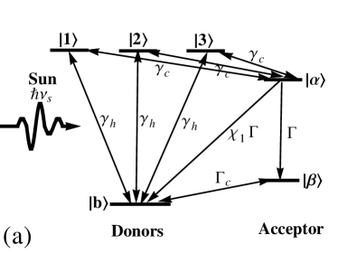
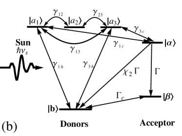
Proceeding with the analysis, we consider a quantum photocell model with the conduction band (CB) states and the valence band (VB) state [depicted in Fig.1(a)] as the donors. And level and level connecting to a load are assumed the acceptor molecule. The excitation of a molecule is simply modeled as a two-level system with the excited state and the ground state . Then the excited electrons driven by solar radiation can be transferred to the acceptor molecule, the conduction reservoir state , with any excess energy radiated as a phonon into the ambient thermal phonons reservoirs. The excited electron is then assumed to be used to perform work, leaving the conduction reservoir state decaying to the sub-stable state at a rate . The recombination between the acceptor and the donor is modeled as (i=1,2) in Fig.1, where is the RRR, a dimensionless fraction. The recombination process brings the system back into the VB state without producing a work current, which could be a significant source of inefficiency. Finally, the state decays back to the VB state at a rate and the cycle terminates. In Fig.1(a), the three donors are assumed to be identical and degenerate, and their three uncoupled excited states have the same excitation levels ===E, and their transition dipole moments are aligned in the same direction, i.e., =e=, where , and is located at . The dipole-dipole interaction only exists in the nearest neighbors and the dipole-dipole couplings are denoted by J= between and , and and in Fig.1(b), but there is no coupling between and . The strength of the dipole-dipole coupling J is much weaker than the excitation energy . The Hamiltonian of the three coupling donors can be written as
| (1) |
where H.c. means Hermitian conjugation, and are the Pauli raising and lowering operators, respectively. The three single-excitation states of the above Hamiltonian are =(++), =(-) , =(-+), and their eigenvalues are obtained as =+J, =, =-J. The dynamics behavior of the donors-acceptor system can describe via the master equations for the three uncoupled donors case in Eqn(2)(shown in Fig.1(a)) and the three dipole-dipole coupled donors case in Eqn(3)(shown in Fig.1(b)) as follows, respectively.
and
where =, = describe the average numbers of photon with frequencies matching the transition energies from the VB state to the CB states in Fig.1(a), and in Fig.1(b) at the temperature =(300 +)K, where stands for the temperature difference. = and = are the thermal occupation numbers of ambient phonons at temperature . = is the corresponding thermal occupation number at the ambient temperature with the energy (-). , , and represent the corresponding thermal occupations at the ambient temperature with energy gaps (-), (-), and (-), respectively. The rates in Eqn. (2) and Eqn. (3) lead to a Boltzmann distribution for the level population ( , is defined as the chemical potential of lead ) when the thermal averages for the photon and phonon reservoirs are in a common temperature. We consider the initial condition to be a fully occupied ground state22 , i.e., = 1.
III Summary and Discussion
In what follows, we calculate the steady solutions of Eqn.(2) and Eqn.(3) for the RRRs, and . Considering the cumbersome expression for and , we follow the numerical approach to carry out the discussion. And we use the following parameters, =0.10 ev, ==0.20 ev, =6 Mev, =0.40 ev, =0.15 ev21 ; 22 . And other parameters are =0.62 ev in Fig.1(a), and =0.62 ev ,=0.45 ev, = =0.15 +) ev, J=0.10 ev, = ==0.15 ev in Fig.1(b).
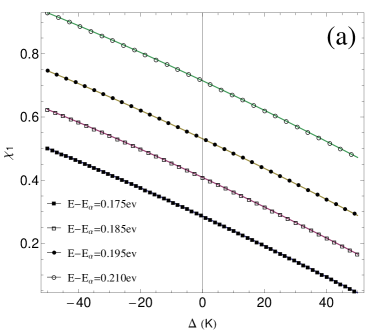
Fig.2 plots the RRR () as a function of the temperature difference (K) with the energy gaps () being the control-parameters. In Fig.2 (a), the linear curves decline with the temperature difference (K), and at room temperature (=0) the RRRs decrease with the increasing energy gaps (). It indicates that in the quantum photocell with three uncoupled electron donors, the increasing circumstance temperature and energy gaps () can block the radiative recombination from the donors to acceptor. Therefore, the transported electrons to VB via the radiative recombination become less and more excited electrons were transported to perform useful work. These features suggest that the quantum photocell with three uncoupled electron donors operates at a slight higher temperature and wider band gap will bring out more excited electrons to perform useful work. However, we must take account of the fact that, increasing the band gap and environmental temperature will cause less absorption and much more phonon-electron scattering. Therefore, Fig.1(a) may indicate that the room temperature with a proper energy gap () is the optimal operating condition for the photocell with three uncoupled electron donors in the real environment.
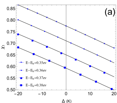
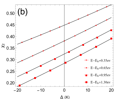
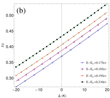
However, a contrary result appears in the case of three dipole-dipole coupled donors in Fig.2(b). It notes that the increasing circumstance temperature promotes the RRRs but the energy gaps () can inhabit the RRR. And at the room temperature (=0) in Fig.2(b), the values of RRR are much smaller than those in Fig.2(a). The reason comes from their difference, i.e., the quantum photocell with three uncoupled donors in Fig.2(a) while with three dipole-dipole coupled donors in Fig.2(b). Therefore, in the condition of higher circumstance temperature, the quantum coherence generated from different electronic transport channels was strengthened in Fig.2(b), which holds back more electrons to perform work but radiate to the VB state directly in the donor molecules. Hence, just taking three dipole-dipole coupled donors into account, the increasing circumstance temperature inhabits the photon-to-charge efficiency. Although, Fig.2(b) demonstrates that the p-n junction with a slightly large energy gap() will decrease the possibility of the electronic radiative recombination in the photocell, increasing the band gap leading to less absorption should be considered in the photocell design.
In the photocell, the gap between the donors and acceptor molecular, () may be an interesting parameter to the RRR. Next, we carry out its influence on the RRR with the gaps ()=0.38 ev, and 0.7 ev in Fig.3(a) and (b), respectively, and other parameters are the same to those in Fig.2. The same physical features are shown in Fig.3 as those in Fig.2. It notes that the ambient circumstance temperatures can suppress the RRR in Fig.3(a) with three uncoupled electron donors but enhance the RRR in Fig.3(b) with three dipole-dipole coupled electron donors, and at the room temperature (=0) the RRRs in Fig.3 (a) and (b) are smaller than those in Fig.2 (a) and (b), respectively. Not only that, but the RRR is inhabited by the decreasing gaps () between the donors and the acceptor molecular in Fig.3. It is intuitively believed that it is not easy for the excited electrons transporting to the external load with a larger gap () but radiative to the VB state . And the curves in Fig.3 both (a) and (b) demonstrate this conclusion.
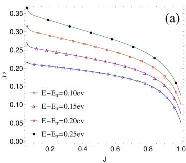
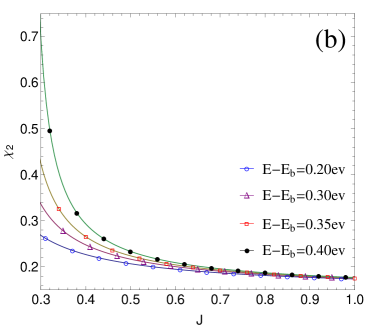
The increasing electrostatic dipole-dipole coupling strength can bring out the stepped-up quantum interference between the different donors. To deeply investigate the quantum interference between the three dipole-dipole coupled donors in this quantum photocell, the following discussion about the RRR versus the electrostatic dipole-dipole coupling strength will be carried out in Fig.4 at room temperature. It shows that monotonically decreases with the increasing in both Fig.4(a) and (b), and the less gap () in Fig.4(a) and () in Fig.4(b) generates the less RRR . However, the sharp decrease of appears about in the range 0.8 1 in Fig.4(a) but appears about in the range 0.3 0.5 in Fig.4(b), and the final values of are in close proximity to 0.05 in Fig.4(a), while the RRRs values infinitesimally approach to 0.2 in Fig.4(b). These results indicate that the increasing electrostatic dipole-dipole coupling strength and the less gaps () and () enhance the quantum interference between the three dipole-dipole coupled donors, which can inhabit the RRR ultimately. And the RRR can be suppressed to a minimum but can’t be canceled out17 due to the radiative upward and downward transition coexisting in the quantum photocell. When the gap () was fixed, the less gaps () and the increasing electrostatic dipole-dipole coupling strength enhance the quantum interference simultaneously, which leads to the suppressed . Then, the larger generates the sharp decrease of about in the range of 0.8 1 in Fig.4(a). But in the case of (=0.05 ev), the increasing gap () cause less absorption solar photons. Therefore, the sharp decrease of appears about in a smaller range about 0.3 0.5 in Fig.4(b).
IV Possible experimental realization
Up to now, we have investigated the features of RRR dependent the circumstance temperature, gaps and the electrostatic coupling strength of the dipole-dipole coupling in this quantum photocell with three electron donors. Now let us suggest some potential experimental researches about this quantum photocell. First of all, two type of energy gaps discussed here display some significant results about the radiative recombination. It manifests that the semiconductor materials with appropriate energy gaps can effectively inhibit radiative recombination. Therefore, seeking a semiconductor material with suitable band gap in experiment may be an interested direction to suppress the radiative recombination. Secondly, the energy gap between the donors and acceptor may be another experimental investigation according our results, and best-effort to reduce this gap is a possible experimental realization for the suppressed RRR. How to align the donors of photocells for an intense electrostatic dipole-dipole coupling strength in the manufacturing process may be another research field. The scenario proposed here may be a different approach for the efficient photon-to-charge conversion and deserve further experimental investigation.
V Conclusion
To summarize, in this work we explored the RRR dependent ambient circumstance temperature, gaps and the electrostatic coupling strength of the dipole-dipole coupling in a quantum photocell system with three electron donors. It showed that the RRR could be suppressed in this photocell with three uncoupled electron donors but be enhanced with three dipole-dipole coupled electron donors by the ambient circumstance temperatures, and the increasing energy gap in the donors, the decreasing gap between the donors and acceptor inhabited the RRR with three dipole-dipole both coupled and uncoupled electron donors. When the photocell was manipulated by the electrostatic dipole-dipole coupling strength at room temperature, the RRR was suppressed to a smaller minimum by the gap between the donors and acceptor than those by different gaps in the donors. These results suggest an encouraging research direction to the high photon-to-charge conversion efficiency via the suppressed RRR in this quantum photocell, and some strategies for the suppressed RRR, such as seeking a semiconductor material with suitable band gap, minimizing the gap between the donors and acceptor and aligning properly the donors for an intense electrostatic dipole-dipole coupling strength deserve the further experimental confirmation.
Acknowledgements.
We thank the financial supports from the National Natural Science Foundation of China ( Grant Nos. 61205205 and 61565008 ), and the General Program of Yunnan Applied Basic Research Project, China ( Grant No. 2016FB009 ).References
- (1) P. Wrfel, Physics of Solar Cells, (Wiley-VCH, Berlin), (2009).
- (2) W. Shockley and H. J. Queisser, J. Appl. Phys. 32, 510 (1961).
- (3) M. A. Green, K. Emery, Y. Hishikawa, W. Warta, E. D. Dunlop, Solar cell efficiency tables (version 48).Prog. Photovolt: Res. Appl. 24, 905, (2016).
- (4) U. Wrfel, M. Thorwart and E. R. Weber, Quantum Efficiency in Complex Systems, Part II: From Molecular Aggregates to Organic Solar Cells, in Semiconductors and Semimetals,(vol. 85, Academic Press, San Diego), (2011).
- (5) O. D. Miller, E. Yablonovitch and S. R. Kurtz, IEEE J. Photovoltaics, 2 , 303 (2012).
- (6) F. H. Alharbi, J. Phys. D: Appl. Phys., 46, 125102 (2013).
- (7) F. H. Alharbi and S. Kais, Renewable Sustainable Energy Rev., 43, 1073 (2015).
- (8) M. Daryani, A. Rostami, G. Darvish, M. K. Morravej Farshi, Opt Quant Electron, 49, 255 (2017).
- (9) C. H. Henry, J. Appl. Phys., 51 , 4494 (1980).
- (10) A. Luque, P. G. Linares, E. Antolin, E. Canovas, C. D. Farmer, C.R. Stanley and A. Marti, Appl. Phys. Lett., 96, 013501 (2010).
- (11) T. Nozawa and Y. Arakawa, Appl. Phys. Lett., 98, 171108 (2011).
- (12) A. Luque and A. Marti, Phys. Rev. Lett., 78, 5014 (1997).
- (13) J. Li, M. Chong, J. Zhu, Y. Li, J. Xu, P. Wang, Z. Shang, Z. Yang, R. Zhu and X. Cao, Appl. Phys. Lett., 60, 2240 (1992).
- (14) J. Bruns, W. Seifert, P. Wawer, H. Winnicke, D. Braunig and H. G. Wagemann, Appl. Phys. Lett., 64, 2700 (1994).
- (15) H. Kasai, H. Matsumura, Sol. Energy Mater. Sol. Cells, 48, 93 (1997).
- (16) A. Luque, J. Appl. Phys., 11, 031301 (2011).
- (17) K. E. Dorfman, M. B. Kim, A. A. Svidzinsky, Phys. Rev. A,84, 053829 (2011)
- (18) M. O. Scully, Phys. Rev. Lett., 104, 207701 (2010).
- (19) A. A. Svidzinsky, K. E. Dorfman and M. O. Scully, Phys. Rev. A, 84, 053818 (2011).
- (20) M. O. Scully, K. R. Chapin, K. E. Dorfman, M. B. Kim and A. Svidzinsky, Proc. Natl. Acad. Sci., 108, 15097 (2011).
- (21) K. E. Dorfman, D. V. Voronine, S. Mukamel and M. O. Scully, Proc. Natl. Acad. Sci., 110, 2746 (2013).
- (22) C. Creatore, M. A. Parker, S. Emmott and A. W. Chin, Phys. Rev. Lett., 111, 253601 (2013).
- (23) K. E. Dorfman, K. E. Dorfman and M. O. Scully, Coherent Optic Phenom,1, 42 (2013).
- (24) R. R. King, D. C. Law, K. M. Edmondson, C. M. Fetzer, et al., Appl. Phys. Lett., 90, 183516 (2007).
- (25) R. R. King, D. C. Law, K. M. Edmondson, et al., Advances in Opto-Electronics,2007, 29523 (2007).