Comparative Study of the Surface Potential of Magnetic and Non-magnetic Spherical Objects in a Magnetized RF Discharge Plasma
Abstract
We report measurements of the time-averaged surface floating potential of magnetic and non-magnetic spherical probes (or large dust particles) immersed in a magnetized capacitively coupled discharge. In this study, the size of the spherical probes is taken greater than the Debye length. The surface potential of a spherical probe first increases, i.e. becomes more negative at low magnetic field (B 0.05 T), attains a maximum value and decreases with further increase of the magnetic field strength (B 0.05 T). The rate of change of the surface potential in the presence of a B-field mainly depends on the background plasma and types of material of the objects. The results show that the surface potential of the magnetic sphere is higher (more negative) compared to the non-magnetic spherical probe. Hence, the smaller magnetic sphere collects more negative charges on its surface than a bigger non-magnetic sphere in a magnetized plasma. The different sized spherical probes have nearly the same surface potential above a threshold magnetic field (B 0.03 T), implicating a smaller role of size dependence on the surface potential of spherical objects. The variation of the surface potential of the spherical probes is understood on the basis of a modification of the collection currents to their surface due to charge confinement and cross-field diffusion in the presence of an external magnetic field.
I Introduction
A spherical object or dust grain attains an equilibrium potential (or floating potential) when it is immersed in a plasma. At the floating potential, it draws a net zero current, i.e., the net flux of electrons and ions to the surface of the spherical object is zero. In low-temperature plasmas, where the electron temperature is much higher than the ion temperature (), the floating potential of the spherical particle mainly depends on the flux of energetic electrons to its surface and is always negative with respect to the plasma potential. In a dusty plasma, which is an admixtures of the plasma species and sub-micron to micron sized solid particles, the charge on the dust grains determines their collective dynamics such as dust acoustic waves Barkan, Merlino, and D’Angelo (1995); Bandyopadhyay et al. (2008); Choudhary, Mukherjee, and Bandyopadhyay (2016); Dharodi, Tiwari, and Das (2014) and vortex motion Vaulina et al. (2004); Saitou and Ishihara (2013); Choudhary, Mukherjee, and Bandyopadhyay (2017); Law et al. (1998); Choudhary, Mukherjee, and Bandyopadhyay (2018); Choudhary et al. (2019). In a dusty plasma, a dust particles are assumed to be spherical capacitors, which allows us to determine the surface potential and the net charge on it.
In recent years, the research field of dusty or complex plasmas has been of interest due to its applications in space or solar plasmas, Goertz (1989, 1984); Mendis and Rosenberg (1994) plasma processing technologies, Selwyn, Heidenreich, and Haller (1991); Watanabe (1997) fusion devices, (Winter, 2000) colloidal solutions Löwen et al. (2011) etc. For studying the collective dynamics of the dust grain medium, the charge on the dust grains has to be known. In the last more than three decades, various experimental methods have been used to obtain the dust charge in an unmagnetized dusty plasma. Barkan, D’Angelo, and Merlino (1994); Goree (1994); Wu and Miller (1990); Walch, Horanyi, and Robertson (1994); Khrapak et al. (2005a) The experimentally measured dust charge values were compared with theoretically obtained values using the orbital-motion-limited (OML) approximation Mott-Smith and Langmuir (1926); Allen (1992) and numerical simulations Khrapak et al. (2005a). The OML theory describes the charging mechanism of sub-micron to micron-sized particles () in the plasma environment. Here, is the radius of the particle and is the electron Debye length. For large dust grains or spherical objects (), the thin sheath theory or the modified OML theory Willis et al. (2010) is suitable to understand the charging mechanism in an unmagnetized plasma.
Nowadays, magnetized dusty plasma are a popular research topic among the dusty plasma community. It is well known that the dynamics of dusty plasmas depends on the characteristics of the background plasma that can be changed in the presence of an external magnetic field. Therefore, the B-field is considered as an external parameter to control the dynamics of the dust grain medium which may allow to us study fluid dynamics, solid state phenomena, turbulence etc. at a microscopic level. Morfill and Ivlev (2009); Bonitz, Henning, and Block (2010) Since the dust charge depends on the background plasma, the estimation of the accurate charge on dust grains (magnetic or non-magnetic) is a challenge depending on the magnetization of the plasma particles. In the last few years, theoretical as well as experimental works have been carried out to estimate the charge on dust grains in the magnetized plasma. Tsytovich et al. Tsytovich, Sato, and Morfill (2003) performed simulations to understand the charging mechanism of micron sized dust particles in a magnetized plasma. It has been claimed that the B-field influences the dust charging mechanism at a strong B-field when the electron gyration radius is greater than the dust radius. Lange Lange (2016) performed a simulation of a magnetized rf plasma and observed a smaller dust surface potential (or charge) at a lower magnetic field. The simulation of Patacchini et al. Patacchini, Hutchinson, and Lapenta (2007) demonstrated the decrease of the dust charge at all values of magnetic field in a collisonless plasma. A recent simulations Kodanova et al. (2019) suggests that the dust charge starts to decrease after a critical value of B-field in a magnetized plasma. Tomita et al.Yukihiro et al. (2009) reported a higher dust surface potential or large dust charge in a weakly magnetized plasma. Apart from analytical and numerical simulation studies, a few experiments have been performed to obtain the dust charge in a magnetized plasma. Kalita et al. Kalita et al. (2015) have measured the dust charge in a weakly magnetized plasma (B 0.05 T) and found a negligible role of the B-field to be negligible on the dust charging mechanism. Tadsen et al. Tadsen, Greiner, and Piel (2018) have observed a reduction of the dust charge up to 50% for nano sized particles at a low magnetic field (B 0.01 T) in an rf discharge. In this work, the charge on nano sized non-magnetic particles is determined by fitting the theoretical dispersion relation of dust–acoustic waves to the experimentally observed dispersion relation. An experimental work of Melzer et al. Melzer et al. (2019) shows a reduction in the dust charge at low magnetic field (B 0.02 T) and nearly constant value up to B 5 T. In their work, the charge on micron sized dust grains is extracted by a normal mode analysis of the dust cluster in the magnetized rf plasma. A similar rf discharge configuration and normal mode analysis technique were used to get the charge on micron sized paramagnetic particles at low B-field (B 0.01 T) and observed a nearly constant values of the dust charge. Puttscher and Melzer (2014) The inconsistencies in the numerically as well as experimentally observed values of the dust charge leave many open questions on the charging mechanism of spherical particles (magnetic and non-magnetic) in a magnetized plasma. Does the dust charge remain unchanged even though the magnetic field modifies the background plasma? How does it depend on the density of the plasma species and the background gas in the presence of B-field? Do magnetic particles attain similar charges than non-magnetic particles? Does the surface potential of a dust grain show a size dependence in a magnetized plasma? Why does the experimentally estimated dust charge not vary according to the theoretical models?
To answer some of these questions, a better understanding of the dust charging in an rf magnetized plasma is required. It is sometimes difficult to measure a small variation in the charge of micron-sized dust grains () while the background plasma parameters are changing in the presence of an external magnetic field. In laboratory experiments, it is easy to directly measure the surface potential of a large spherical conducting body (), which can be considered as a large dust grain in a magnetized plasma. The surface potential variation of a spherical probe (or large dust grain) in presence of a external magnetic field can provide information of a background plasma to minimize the errors in measuring the charge on micron-sized particles () in a magnetized dusty plasma. It is well known that the charge on an individual dust particle is higher (more negative) than that of a particle in the dust grain cluster. However, the variation of the dust charge of a single dust grain and dust cluster would be similar. Sometimes the surface potential of a large dust grain also helps to understand the interactions among the micron-sized dust grains in a magnetized plasma. Keeping this in mind, experiments are planned to measure the surface potential of magnetic and non-magnetic spherical probes (or large dust particles) in a magnetized rf discharge.
The investigations are carried out in a magnetized complex plasma device where an rf glow discharge is ignited between two electrodes, and a superconducting electromagnet is used to introduce the magnetic field. The surface potential of various sized magnetic (stainless steel, SS-430, = 1800) and non-magnetic (bronze, 1) spherical probes (or large dust grains) has been measured in the unmagnetized and magnetized plasma at various discharge conditions. At a lower magnetic field, the magnitude of the surface potential of a spherical object increases to a maximum value and then starts to decrease with increasing the strength of the B-field. This trend is found to be independent of the size and types of materials of the spherical object. However, the charging mechanism of magnetic and non-magnetic spherical objects depends on the magnetic field. The charge or surface potential of a non-magnetic spherical probe in the plasma are found to be smaller (less negative) than that of a magnetic sphere after a threshold value of B-field. Experimentally observed results are explained on the basis of the current collection to the surface of the object in the presence of a magnetic field.
The manuscript is organized as follows: Section II deals with the detailed description of the experimental set-up and the magnetized plasma production. The surface floating potential variation at various discharge conditions in unmagnetized and magnetized plasmas are discussed in Section III. Qualitative and quantitative explanations of the surface potential variation for magnetic and non-magnetic spheres are given in Section IV. A brief summary of the work along with concluding remarks is provided in Section V.
II Experimental Setup and Diagnostics
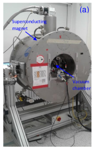
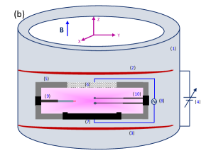
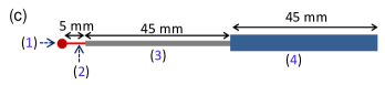
The experimental setup (magnetized dusty plasma device) consists of an aluminum vacuum chamber and a superconducting electromagnet, which is shown in Fig. 1(a). This device was previously used to study the dusty plasma in a strong magnetic field Schwabe et al. (2011). The schematic diagram of the experimental setup is presented in Fig .1(b). The superconducting electromagnet has a Helmholtz coil configuration to produce a uniform magnetic field at the center of the vacuum chamber. The superconducting magnet consists of a helium compressor, a cooling head, 8 sensors for temperature measurements, and a superconducting magnet power supply (0 to 80 A). At first, the plasma chamber is evacuated below Pa using a pumping system consisting of a rotary and turbo molecular pump (TMP). The experiments are performed in an argon plasma and the pressure of the argon gas inside the chamber is controlled by a mass flow controller (MFC) and a gate valve controller. A 13.56 MHz rf generator with matching network is used to ignite the gas discharge between a stainless steel electrode (lower) and an indium tin oxide (ITO) coated glass electrode (upper) of 6.5 cm diameter. Both electrodes are separated by 3 cm. For the comparative study, stainless steel (SS-430, = 1800, magnetic) spherical probes of radius 1.0 mm, 1.25 mm and 1.7 mm and a bronze (non-magnetic, 1) spherical probe of radius 1.5 mm are used. Opposite radial ports are used to insert the spherical probes and the emissive probe for measuring the floating and plasma potentials. The measurements are taken in the homogeneous plasma region where the magnetic field is uniform. The spherical probes are placed in the plasma using a ceramic tube of diameter 2 mm which protrudes into the plasma by a feed-through in the chamber wall and holds the spherical probes at its end. To avoid the floating potential perturbation due to the connecting aluminium tube (it holds ceramic tube), the length of the ceramic tube is taken longer so that it only remains in contact with the plasma, as is shown in Fig. 1(c). We have made connection to the spherical probe in such a way to keep connection area as small as possible compared to the total surface area. For measuring the time-averaged floating potential () of a spherical probe (or large dust grain), a high-impedance voltage divider (1200:1) is used. The spherical probe is connected to a high-value resistor ( = 120 M) to minimize the current flowing in the voltage divider circuit. First the voltage drop () with respect to ground due to this small current is measured across a low value resistor ( = 100 k) and then the floating potential of the spherical probe () is calculated by using the expression, . In the present set of experiments, an emissive probe made of tungsten of radius 0.05 mm, placed perpendicular to the magnetic field lines, is used to measure the time-averaged plasma potential (). The floating point method technique is used to measure in the absence and presence of the magnetic fieldSheehan and Hershkowitz (2011); Balan et al. (2003); Fujita et al. (1980); Bradley, Thompson, and Gonzalvo (2001); Choudhary (2017). It has been claimed in some studies that the floating potential method underestimates the plasma potential Schrittwieser et al. (2005); Sheehan et al. (2011). In view of this, we have compared the plasma potential values obtained from the cold single Langmuir probe and emissive probe. The floating potential method estimates the plasma potential lower by 2 V than estimated by a cold probe. This potential difference is within the error of 15 %. Thus, the floating potential method is useful to get an approximate value of plasma potential to obtain .
III Measurements of surface potential of spherical objects
A spherical object or dust grain immersed in a plasma attains a negative potential to balance both the electrons and ions currents to its surface. This equilibrium surface potential with respect to the plasma potential () is termed as surface potential () of the spherical object Chen (2003); Conde (2011). It is stated in ref.Willis et al. (2010) that different analytical theories are valid for estimating the surface potential of an object in a Maxwellian plasma. The orbital motion limited (OML) theory (Allen, 1992) is applicable for small objects () and the surface potential is derived by balancing the electrons and ions fluxes to the surface of an object [ref.Willis et al. (2010); Beadles, Wang, and Horányi (2017)]
| (1) |
where , and are the electron and ion temperatures, and are the electron and ion masses, respectively. For the large spherical object (), the thin sheath theory (TS) is applicable to obtain . The surface potential for such spherical objects can be estimated by Stangeby (2000); Willis et al. (2010)
| (2) |
In the transition region between OML and TS theory, the orbital motion (OM) theory estimates the surface potential. Then is found to be a straight line fit on a log plot between the OML limit and TS limit. Beadles, Wang, and Horányi (2017); Willis et al. (2010) It is clear from Eq. 2 and Eq.3 that the floating surface potential () of a large spherical object or small dust grain has a approximately linear relation with ,
| (3) |
Here is a constant varying from 2.5 to 4 in the transition region between the OML and TS () for an unmagnetized argon plasma (). Willis et al. (2010); Beadles, Wang, and Horányi (2017) In a magnetized plasma, also depends on but the value of may be lower or higher than that of an unmagnetized plasma. For getting the value of the floating surface potential, , of a spherical conducting probe in the plasma, it is necessary to measure the plasma potential () as a reference potential. By knowing the surface potential (), the charge on the surface () of a small dust grain () and large dust grain () can be estimated using the different approximations Delzanno and Tang (2015).
III.1 Surface potential of spherical probes in unmagnetized plasma
The present work deals with spherical probes (large dust grains) of radius larger than the electron Debye length, i.e., . Stainless steel spheres of radius 1.0 mm, 1.25 mm and 1.7 mm are used to study the size dependence of the surface potential. A pair of spherical probes of different sizes (separated by 14 mm) is placed in the plasma volume, as shown in schematic diagram (see Fig. 1(b)). It should be noted that both probes are placed in the horizontal (X–Y) plane. The distance between the probes is decided after successive measurements of for both spherical probes at similar discharge conditions in the presence of B-field. These successive measurements are taken at the center of the plasma volume whereas the simultaneous measurements on both sides of the center are performed to keep both probes in the homogeneous plasma background. The difference between the successive and simultaneous measured values of at the same discharge condition are found to be 0.3 V, which is 2–3 % of the actual value. Therefore, we neglect the shadow/potential overlapping effect of an individual sphere on each other during the simultaneous measurements of for the comparative study. It is known that dust grains (m to mm) respond only to a very low frequency external field ( 1 to 100 Hz). They do not respond to a high frequency field of an rf discharge. In view of this, it is our aim to measure the time-averaged or DC potential of the spherical probes in the rf discharge.
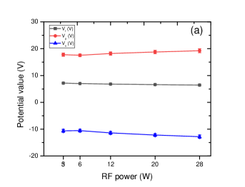
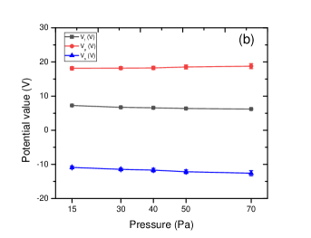
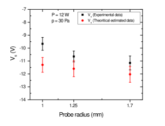
Fig. 2(a) and Fig. 2(b) show the time-averaged , and for different rf powers at constant pressure and for different pressures at constant power, respectively. We see a slight variation in the potentials at different discharge conditions in the absence of the magnetic field (B = 0 T). To see the effect of the object size on at a given discharge condition (P = 12 W and p = 30 Pa), the floating potential of the stainless steel spherical probes of different sizes are measured. The variation of for different sized spherical probes is depicted in Fig. 3. For getting the theoretical values of for the given discharge conditions, the plasma density () and electron temperature are measured using the double probe Johnson and Malter (1950); Nobata (1963); Choudhary (2017).
The double probe is made of two tungsten wires (or single probes) of radius 0.15 mm and length 8 mm. Both probes are separated by 7 mm. At p = 30 Pa, the plasma is moderately collisional; therefore the collisionless OML theoryMott-Smith and Langmuir (1926); Chen (2003) of cylindrical probe underestimates the plasma density. To measure the approximate plasma density, the collisional model for the ion current to the cylindrical probe is used Tichy et al. ; Kudrna and Passoth (1997). The variation of and with different rf powers is depicted in Fig. 4. At this discharge condition, is 0.3 mm, which gives . The theoretically estimated values corresponding to this Willis et al. (2010) are plotted with experimental data (Fig. 3) and found to be in good agreement within the error of 10 % , which is expected due to the plasma collisionality. It confirms that the surface potential of a spherical object depends on its size in the a low temperature unmagnetized plasma ().
III.2 Surface potential of spherical probes in magnetized plasma
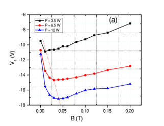
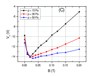
For producing the magnetized plasma, a B-field perpendicular to the plane of electrode (in Z-direction) is applied. In Fig. 5 the surface potential of the SS probe of radius 1.25 mm and bronze probe of radius 1.5 mm at various strengths of the magnetic field are presented. It should be noted that the B-field is uniform in the entire plasma region at B = 0.2 T. The plots in Fig. 5(a) show the variation of for different input rf powers, P = 3.5, 6.5, and 12 W at a fixed pressure, p = 30 Pa. It is clearly seen in this figure that first increases (becomes more negative) at low B (B 0.05 T), attains a maximum value and after that it starts to decrease (becomes less negative) at higher magnetic field strength (B 0.05 T). The rate of change of is observed to be different in the low B-field region (B 0.05 T) and high B-field region (B 0.05 T) at a given input power. It is also noticed that attains its maximum value at low B-field at lower input power (P = 3.5 W) and at high B-field at higher input power (P = 12 W).
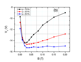
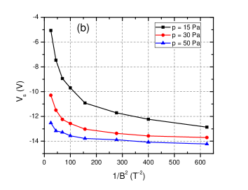
The variation of at a given power (P = 12 W) and different pressures, p = 15, 30 and 50 Pa with the magnetic field strength is presented in Fig. 5(b). The rate of change of is less at higher pressures for B 0.05 T. It confirms the dependence on the plasma collisionality. Moreover, achieves its maximum value at lower B if the gas pressure is reduced. A similar trend of variation is observed for the different sized magnetic spherical probes in the presence of B-field. The variation of against B for a non-magnetic sphere (bronze) is depicted in Fig. 5(c). The surface potential shows a similar trend to that of the magnetic sphere (Fig. 5(b)) in the presence of a B-field. However, the rate of change of for the non-magnetic and magnetic sphere are different at the same discharge conditions.
III.3 Comparison of surface potentials
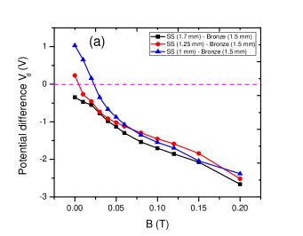
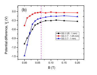
The data of the magnetic probes and the non-magnetic probe are compared to see the fundamental differences in the charging mechanism in a magnetized plasma. Comparison of for the magnetic and non-magnetic spheres at different B-field is depicted in Fig. 6. We take simultaneous measurements of the floating potential of a pair of spherical probes at a given discharge condition. At the same discharge condition, the floating potential is measured for different pairs of spherical probes with different sizes. It should be noted that the error in measurement is 2 % and the reference potential () is common for all measurements at similar discharge conditions. This gives almost an accurate trend of the potential difference. In Fig. 6(a) the surface potential of the bronze probe has been subtracted from the magnetic ones. It is reconstructed from the data for different sized ( = 1.0 mm, 1.25 mm and 1.7 mm) SS and bronze ( = 1.5 mm) probes to compare the size dependence in the presence of the B-field. It is clear from Fig. 6(a) that the smaller sized magnetic sphere (e.g., = 1 mm) has a higher value of than the non-magnetic sphere (e.g., = 1.5 mm) above B 0.03 T. This difference in increases with increasing B-field. It means that equally sized magnetic and non-magnetic spherical objects or dust grains have different charges in a magnetized rf discharge. Fig. 6(b) compares the surface potential of the different sized magnetic spheres to see the role of the B-field in determination of . It is seen in Fig. 6(b) that the difference in for different sized magnetic probes decreases with increasing magnetic field and remains almost constant at higher B-field (B 0.05 T). It shows that remains almost constant for all sized spherical probes at higher B-field, B 0.05 T. In other words, has a much weaker size dependence in a magnetized rf plasma.
IV Discussion
The surface potential of a spherical probe or dust grain is determined by the electron and ion currents to its surface. In a low temperature plasma, where , the surface potential is mainly determined by . Since , the surface potential is always negative with respect to the plasma potential. Here, and are the electron and ion thermal velocities, respectively. In an unmagnetized rf discharge plasma (at B = 0 T), the surface potential of a spherical object of the radius is estimated using the theoretical value of in the transition region between OML and TS regions Willis et al. (2012, 2010). A slight variation in (see Fig. 4) with increasing the power and pressure demonstrates a negligible change in in the unmagnetized plasma. (see Fig. 2).
With the application of a magnetic field, the gyro-radius of electrons () and of ions () decreases with increasing B-field. Due to the mass differences, electrons are magnetized at lower magnetic field than ions, i.e., . The electrons and ions are considered to be magnetized when the gyration frequency of the respective species () is higher than the collisonal frequency (), i.e., . Here is the collisional mean free path for the respective species. In our experiments (p = 15 to 50 Pa and P = 3.5 to 12 W), and are observed to be vary between 6 to 3 and 3–5 eV, respectively. The mean free path of electrons, 14-3 mm and ions, 0.2-0.08 mm. Here and are the collision cross sections of electrons and ions with argon atoms, respectivelyBenyoucef et al. (2010) and is the neutral gas density. The electron gyro-radius varies between 0.5-0.7 mm for B = 0.01 T at given discharge conditions. Therefore, the condition meets even below B = 0.01 T. With increasing the strength of the magnetic field (B 0.01 T), continuously decreases and electrons are fully magnetized. Ions are assumed to be at room temperature, i.e, . The ion gyro-radius at B = 0.2 T is estimated as 0.5 mm, which indicates that ions get magnetized at high magnetic field, B 0.2 T. It essentially means that in the range of the magnetic field (B 0.2 T), only electrons are magnetized but ions are assumed to be unmagnetized. In a magnetized plasma, the currents and to the surface of a spherical probe are altered when the condition, , is satisfied. Here is the electron Debye length. In the present work, varies between 0.2 to 0.5 mm for the given range of plasma parameters. It shows that the electron current gets changed as a B-field is introduced. The ions do not fulfil this criteria at B 0.2 T, therefore, the ion current to the surface of the spherical object is considered to be unaffected.
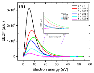
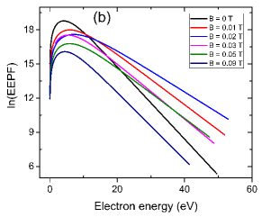
In an unmagnetized plasma, a constant flux of energetic electrons is lost to the chamber wall. The magnetic field confines the electrons, which definitely reduces the electrons loss to the chamber wall. Therefore, it is expected that the density of the energetic electrons would be increased as the magnetic field is introduced. To see the effect of the B-field on the electron population, the electron energy distribution function (EEDF) is measured using a tungsten cylindrical probe of length 8 mm and radius 0.15 mm. The probe is positioned perpendicular to the discharge axis or magnetic field lines. At discharge condition (P = 12 W and p = 30 Pa), therefore, the conventional probe theory of a cylindrical probe is used to get the EEDF. It should be noted that the plasma anisotropy in presence of the magnetic field depends on the parameter B/p and this value should be higher than T/Pa Behnke et al. (1999). Since in our set of experiments, the ratio of B/p varies from to T/Pa, it does not exceed T/Pa. Therefore, we do not expect any substantial anisotropy of the plasma or EEDF in our measurements. It should also be noted that the second derivative probe method gives a reliable EEDF in the range of the diffusion parameter Demidov et al. (1999) Popov et al. (2012). Here, is constant and we assumed 4/3 for our pressure regime. In our case, diffusion parameter has the value 15 for B 0.1 T; therefore, this method is used to get the EEDF to show the increase in the energetic electron population as the B-field is turned on. The EEDF is estimated from the second derivative of the probe I-V characteristics with respect to the probe voltage Godyak (1990); Kudrna and Passoth (1997); Popov et al. (2012),
| (4) |
where = eV = e(), is the electron current to probe, is the probe bias, is the plasma potential and is the area of probe. The EEDF with magnetic field at p = 30 Pa and P = 12 W is shown in Fig. 7(a). The population of the cold (or lower energy) electrons, which are reaching the probe, decreases with increasing B-field whereas the population of the energetic electrons increases at low B 0.05 T (see inset image). It means that the energetic electrons can easily reach this probe surface at low B-field.
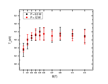
It is obvious that the average electron energy will increase due to the increase of the density of energetic electrons. It means is expected to increase while the magnetic field is introduced. Since the variation in affects the surface potential of a spherical object (see equation 3), it is measured using a double or single probe at various strengths of the B-field. The inverse slope of = with respect to (see Fig. 7(b)) gives . It should be noted that the single probe used to obtain the EEDF is not compensated and overestimates , therefore, errors concerning is expected at low B-field. At higher B (B 0.09 T), the secondary plasma around the probe tip during the positive bias does not give true I–V characteristics, which is also a cause error in measurement even though it is rf compensated. In view of this, a double probe is used to obtain the approximate value of upto B 0.15 T. The double probe theory Johnson and Malter (1950) estimates reliable plasma parameters ( and ) in rf discharges if electrons obey the Maxwellian distribution, i.e., the EEDF should be Maxwellian in the presence of the B-field. In Fig. 7(b), is plotted against the electron energy E for different values of B. The against E shows the characteristics of a Maxwellian plasma Godyak, Piejak, and Alexandrovich (1993) in the experiments. Fig. 8 represents the variation of the electron temperature () with magnetic field at p = 30 Pa and P = 6.5 and 12 W.
In the magnetized plasma, the net electron current to the spherical probe is a sum of the electron currents to different positions on the probe Patacchini, Hutchinson, and Lapenta (2007). In the present experiments, it is difficult to estimate the electron current as a function of position (with respect to the magnetic field direction) on the spherical probe surface Patacchini, Hutchinson, and Lapenta (2007). Therefore, a simple model by considering the net electron current () in two possible directions along the B-field () and transverse to the B-field () is used to explain the observed results qualitatively. Here and are assumed to be the electron current components at a given position on the spherical probe with respect to the magnetic field direction. The total electron current to the surface of a spherical probe is = + , which determines the floating surface potential of a probe in a magnetized plasma. It should be noted that the electron motion transverse to the B-field is much more hindered than that of along the B-field in the moderately collisional plasma. In other words, is reduced much more than in a magnetized plasma Bohm, Burhop, and Messey (1994); Sanmartin (1970), i.e., , where and are the transverse and longitudinal diffusion coefficients, respectively.
There are two possible diffusion processes: the first one is the drain diffusion and the second one is the collisional diffusion. In drain diffusion, electrons may change their direction and cross the B-field during the motion in rf oscillating sheath field of a spherical object. In collisional diffusion, the gyrating electrons collide with background neutrals and diffuse across B-field with a higher rate Bohm, Burhop, and Messey (1994). The drain diffusion mainly dominates over the collision diffusion in a low pressure magnetized plasma. Since the present work is performed in a moderately collisional plasma, the collisional diffusion process is considered to be more effective. For moderately collisional low temperature magnetized plasmas, the collisional transverse diffusion coefficient is , where is the diffusion coefficient in the absence of a B-field, is the electron cyclotron frequency and is the electron–neutral collision time Curreli and Chen (2014); Chen (1984); Bohm, Burhop, and Messey (1994).
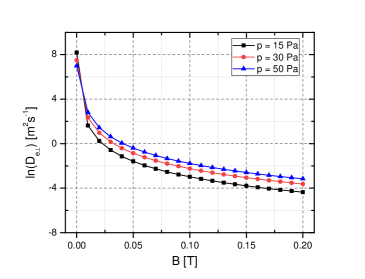
In a collisionless magnetized plasma, electrons motion is restricted by the magnetic field in the transverse direction. Therefore, the (or ) play a dominant role in determination of the surface potential (or charge) of the dust grain in the presence of magnetic field Patacchini, Hutchinson, and Lapenta (2007). The logarithmic plots of transverse diffusion coefficient, , is shown in Fig. 9 which show a reduction in after a magnetic field strength of 0.01 T. The value of increases with the pressure while the magnetic field strength (B 0.02 T) is kept constant, which is also illustrated in Fig 9.
In the low magnetic field regime (B 0.05 T), the increase in (see Fig. 8) enhances the surface potential (more negative) of a spherical probe according to equation 3. Now, the probe collects a higher net current () than . Here, represents an equilibrium electron current to the spherical probe in unmagnetized plasma. This can also be understood on the basis of energetic electron population. Experimentally, the dominating role of energetic electrons in the charging process of a spherical object or dust grain in the plasma has been confirmedArnas, Mikikian, and Doveil (1999). Since the Larmor radius of the energetic electrons ( 20 eV) lies between 1.5 mm to 0.4 mm for B 0.05 T, energetic electrons are considered to be weakly magnetized. Since decreases in this B-field regime (B 0.05 T), the net electron current to spherical surface should be lowered. However, an opposite behaviour (large or ) is observed at low B-field because of the confinement of energetic electrons (or higher ). The higher charges on the dust grains or more negative surface potential in a weakly magnetized plasma is also observed numerically by Tomita et al.Yukihiro et al. (2009). They claimed a larger absorption cross section for electron capture on the dust surface in the presence of a magnetic field. In the present study, higher charges on a spherical probe is due to the increase of for the higher magnetic field (see Fig. 8).
.
At higher B-field (B 0.05 T), a lower value of the mean free path () increases the electron-neutral collision frequency, resulting in a reduction of . A slight reduction in at higher B is seen in Fig. 8. At fixed gas pressure, transverse diffusion coefficient () decreases with the increasing magnetic field (see Fig. 9) which causes reduction in . It is also observed in numerical simulations that start to decrease with increasing the B-field. However, this reduction in is small compared to the reduction in in the magnetic field regime (B 0.15 T). Therefore, it is assumed that the reduction in to the spherical probe could be a possible cause of lower or less negative surface potential at high B-field (B 0.05 T), which is shown in Fig.5.
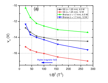
Since (or ) varies with at a given pressure, should has a dependence. In Fig. 10(a), is plotted against for different spherical probes between B = 0.06 T to 0.2 T. Fig. 10(a) clearly indicates that decreases linearly with between B 0.06 T to 0.15 T for an rf power of 12 W. However, the upper B-field value shifts to a slightly lower value (B 0.10 T) for the low power discharge (P = 6.5). Since plasma density is different in both cases (P = 12 W and 6.5 W) at p = 30 Pa, different rates of reduction of with are expected. The plots of against for different pressures at given power (P = 12 W) is shown in Fig. 10(b). We also see a linear variation of with below B 0.12 T and a non-linear reduction in above B 0.12 T (above p 30 Pa). For low pressure case (p = 15 Pa), the non-liner behaviour of is observed at magnetic field of 0.10 T. The different linear rates of at different pressures (Fig. 10(b)) are expected because of different plasma backgrounds (plasma density and ) at a fixed input rf power and different gas pressures. In a similar plasma background, we could expect a constant linear rate of with at different pressures according to the theoretical estimation as shown in Fig. 9. It shows that the reduction in (or ) is mainly due to the lower value of in this magnetic field regime.
At strong magnetic field strength, the contribution of to starts to reduce and a larger contribution comes from Sanmartin (1970). Hence the role of (or ) becomes more important in determination of the surface potential. In the present experiments, does not decrease linearly with above B 0.12 T (Fig. 10) except for the low density plasmas (p = 30 Pa, P = 6.5 W and p = 15 Pa, P = 12 W). In moderately collisional plasma, a reduction in is expected while the magnetic field increases but it could be comparable or larger than of at strong B-field Sanmartin (1970). The non-linear characteristics of against above B 0.12 T (see Fig. 10) is expected due to a dominant role of along with for determining the surface potential. In some other experiments and simulations a reduction in of a spherical object with increasing magnetic field has also been reported. Tadsen, Greiner, and Piel (2018); Lange (2016); Dote, Amemiya, and Ichimiya (1964); Khrapak et al. (2005a).
It is known that the current to the spherical probe decreases with increasing or decreasing . At given finite B-field, increases with increasing the electron-neutral collisions or gas pressure, which leads to an increase of . At finite B-field (B 0.01 T), has slightly larger value at higher pressure (p = 50 Pa) than at lower pressure (p = 15 Pa), as shown in Fig. 9. The difference in for different pressures at finite B-field is one of the possible causes for the different values of in the presence of a magnetic field (Fig. 5(b)). The spherical surface collects more electron current at higher pressure (p = 50 Pa) because of the large value of . The lower value of causes a smaller electron current to the spherical probe. Therefore, the spherical probe has a higher value (more negative) of at p = 50 Pa than at p = 15 Pa (Fig. 5) in the magnetized plasma (B 0.05 T). These results confirm the dominating role of the collisional diffusion over the drain diffusion in a moderately collisional magnetized plasma.
It should be noted that in an unmagnetized plasma (B = 0 T), the dust charge or surface potential decreases with increasing the pressure due to the higher ion-neutral collision frequency Khrapak et al. (2005b). It is also known that collisions of plasma species with neutrals retard the motion along the magnetic field, hence reduction in is expected with increasing the gas pressure. Since ions are unmagnetized below the magnetic field of 0.2 T, the role of ions is negligible than the electrons in determination of the surface potential in this given magnetic field regime (B 0.2 T). Due to the smaller gyro-radius of electrons (higher gyro-frequency) above B 0.05 T, the electron-neutral collision frequency is found to be larger. It means that collisions lower the more effectively than in the magnetized discharge. Hence the role of ion current for determining the surface potential at different pressures (p = 15 to 50 Pa) is assumed to be negligible above B 0.05 T. The higher negative value of at higher pressure also confirms a dominant role of in reduction of the net electron current () or the surface potential in the magnetized plasma.
The difference in for magnetic (stainless steel) and non-magnetic (bronze) spherical objects (Fig. 6) is understood on the basis of field line distribution around a spherical body in a magnetized plasma. Since decreases faster than with the magnetic field, mainly responsible for the reduction in (or ). The magnetic flux density on either side of the magnetic sphere is less than that inside of it in the presence of a magnetic field (see Fig. 3.7 of ref Fagan (2013)), which enhances to the object surface due to the large value of that varies with . Thus, the electron current, , to the magnetic sphere increases making the surface of the spherical object more negative (higher ) in the presence of B-field. In the case of the non-magnetic object (copper bronze), the magnetic flux density on either side of the sphere is slightly larger than that inside of it due to the diamagnetic characteristics of copper. The B-field line density on either side of the non-magnetic sphere is expected to be higher than that of around the magnetic sphere, which reduces to the object surface. The lower value of the electron current () to the non-magnetic sphere makes surface less negative. Hence a magnetic sphere has a higher value (more negative) of than that of a non-magnetic sphere (see Fig. 6(a)) above a finite value of B-field (B 0.03 T).
The qualitative description presented here provides a better understanding of the observed surface potential variation for magnetic and non-magnetic spherical probes (or large dust grains) in a magnetized rf discharge. We have provided a possible charging mechanism of magnetic and non-magnetic particles based on the reduction of electron current to spherical surface. To the best of our knowledge, at present there is not an analytical or simulation work for a moderately collisional magnetized plasma to support our claim. Therefore it may be possible that another charging mechanism of magnetic and non-magnetic spherical particles plays a role in a magnetized plasma.
V Conclusion
The surface potential of magnetic (stainless steel) and non-magnetic (bronze) spherical objects in a magnetized rf discharge at various discharge conditions is measured. A 13.56 MHz rf generator is used to produce the plasma between a transparent indium tin oxide (ITO) coated glass electrode and a metal electrode. A superconducting electromagnet with Helmholtz coils configuration is used to introduce an external magnetic field. The vacuum chamber is placed at the center of the magnet to perform the experiments in a uniform magnetic field. The surface potential of different sized magnetic spherical probes ( = 1.0 mm , 1.25 mm and 1.7 mm) is measured and compared with a non-magnetic spherical probe ( = 1.5 mm) in the plasma at different strengths of the B-field. The main findings of the experimental studies are listed below:
-
1.
The surface potential () of the spherical object () depends on its size in the unmagnetized plasma.
-
2.
The surface potential of a spherical object either magnetic or non-magnetic increases at the low magnetic field (B 0.05 T), attains a maximum value and starts to decrease with further increasing the strength of the external magnetic field (B 0.05 T). The rate of change of the surface potential in the magnetized plasma strongly depends on the gas pressure as well as the plasma parameters ( and ).
-
3.
The surface potential of magnetic spherical objects or large dust grains is found to be higher (more negative) than that of a non-magnetic sphere at the higher magnetic field (B 0.04 T).
-
4.
The surface potential of the spherical objects loses its size dependence characteristics in the rf discharge with the application of an external magnetic field (B 0.05 T).
The magnetic field reduces the loss of energetic electrons to the wall and confines them in the plasma volume. The average energy of bulk plasma electrons or increases due to the confinement of energetic electrons. An increase in energetic electron population or at lower B (B 0.05) increases the electron current to the probe surface. Hence, the surface potential increases (more negative) with B and attains its peak value between B = 0.01 T and 0.05 T for different discharge conditions. With increasing the B-field (B 0.05 T), the electrons motion transverse to the B-field as well as along the B-field is hindered, resulting in a lower electron current to the probe surface. The reduction of the net electron current makes the spherical object less negative. Since ions are assumed to be unmagnetized for the given range of the magnetic field, the role of the magnetic field on the ion current is considered to be negligible. Thus, the electron current determines the surface potential, given by the balance of the electron and ion currents. The value of depends on the magnetic field line density around a spherical object which affects the current to the surface of the object. Therefore, the surface potential is lower (or less negative) for a non-magnetic sphere than for a magnetic sphere in the magnetized plasma.
This work highlights the role of the external magnetic field as well as the types of material of the spherical objects (large dust grains) on the surface potential in a low-temperature plasma. These findings will directly help to estimate the true charges on sub-micron to micron sized dust grains () in magnetized dusty plasma experiments. It has been confirmed that electron temperature increases as the magnetic field is introduced, which definitely indicates the higher dust charges at lower magnetic field. However, many simulations and experimental works suggest either no changes or less negative charge on the dust grain at low B-field. We expect the reduction in the charge of dust particles () similar as for spherical probe () at strong magnetic field. Interestingly, the smaller magnetic or paramagnetic dust grains may acquire a more negative charge on their surface as compared to the non-magnetic dust grains in a magnetized dusty plasma. In the future, our focus will be on the direct or indirect measurement of the charge on dust grains () in a magnetized dusty plasma to understand the dynamics of the dust grain medium. The reported experimental work may be a motive for researchers to develop an analytical or simulation model to understand the charging mechanism of magnetic and non-magnetic spherical particles in a strongly magnetized plasma.
VI Acknowledgement
This work is supported by the Deutsche Forschungsgemeinschaft (DFG). The authors are grateful to Felix Becker for his assistance in making spherical probes and supporting experiments. The authors are also thankful to M. Kretschmer for the experimental assistance.
References
- Barkan, Merlino, and D’Angelo (1995) A. Barkan, R. L. Merlino, and N. D’Angelo, “Laboratory observation of the dust-acoustic wave mode,” Phys. Plasmas 2, 3563–3565 (1995).
- Bandyopadhyay et al. (2008) P. Bandyopadhyay, G. Prasad, A. Sen, and P. K. Kaw, “Experimental study of nonlinear dust acoustic solitary waves in a dusty plasma,” Phys. Rev. Lett. 101, 065006 (2008).
- Choudhary, Mukherjee, and Bandyopadhyay (2016) M. Choudhary, S. Mukherjee, and P. Bandyopadhyay, “Propagation characteristics of dust–acoustic waves in presence of a floating cylindrical object in the dc discharge plasma,” Physics of Plasmas 23, 083705 (2016).
- Dharodi, Tiwari, and Das (2014) V. S. Dharodi, S. K. Tiwari, and A. Das, “Visco-elastic fluid simulations of coherent structures in strongly coupled dusty plasma medium,” Physics of Plasmas 21, 073705 (2014).
- Vaulina et al. (2004) O. S. Vaulina, A. A. Samarian, O. F. Petrov, B. James, and F. Melandso, “Formation of vortex dust structures in inhomogeneous gas-discharge plasmas,” Plasma Physics Reports 30, 918–936 (2004).
- Saitou and Ishihara (2013) Y. Saitou and O. Ishihara, “Dynamic circulation in a complex plasma,” Phys. Rev. Lett. 111, 185003 (2013).
- Choudhary, Mukherjee, and Bandyopadhyay (2017) M. Choudhary, S. Mukherjee, and P. Bandyopadhyay, “Experimental observation of self excited co-rotating multiple vortices in a dusty plasma with inhomogeneous plasma background,” Physics of Plasmas 24, 033703 (2017).
- Law et al. (1998) D. A. Law, W. H. Steel, B. M. Annaratone, and J. E. Allen, “Probe-induced particle circulation in a plasma crystal,” Phys. Rev. Lett. 80, 4189–4192 (1998).
- Choudhary, Mukherjee, and Bandyopadhyay (2018) M. Choudhary, S. Mukherjee, and P. Bandyopadhyay, “Collective dynamics of large aspect ratio dusty plasma in an inhomogeneous plasma background: Formation of the co-rotating vortex series,” Physics of Plasmas 25, 023704 (2018).
- Choudhary et al. (2019) M. Choudhary, R. Bergert, S. Mitic, and M. H. Thoma, “3-dimensional dusty plasma in a strong magnetic field: Observation of rotating dust tori,” https://arxiv.org/abs/1910.07846 0, 0 (2019).
- Goertz (1989) C. K. Goertz, “Dusty plasmas in the solar system,” Reviews of Geophysics 27, 271–292 (1989).
- Goertz (1984) C. Goertz, “Formation of saturn’s spokes,” Advances in Space Research 4, 137–141 (1984).
- Mendis and Rosenberg (1994) D. A. Mendis and M. Rosenberg, “Cosmic dusty plasma,” Annu. Rev. Astron. Astrophys. 32, 419–63 (1994).
- Selwyn, Heidenreich, and Haller (1991) G. S. Selwyn, J. E. Heidenreich, and K. L. Haller, “Rastered laser light scattering studies during plasma processing: Particle contamination trapping phenomena,” J. Vac. Sci. Technol. A 9, 2817–2824 (1991).
- Watanabe (1997) Y. Watanabe, “Dust phenomena in processing plasmas,” Plasma Phys. Control. Fusion 39, A59–A72 (1997).
- Winter (2000) J. Winter, “Dust: A new challenge in nuclear fusion research?” Phys. Plasmas 7, 3862–3866 (2000).
- Löwen et al. (2011) H. Löwen, C. P. Royall, A. Ivlev, and G. E. Morfill, “Charged colloidal suspensions and their link to complex plasmas,” AIP Conference Proceedings 1397, 201–210 (2011).
- Barkan, D’Angelo, and Merlino (1994) A. Barkan, N. D’Angelo, and R. L. Merlino, “Charging of dust grains in a plasma,” Phys. Rev. Lett. 73, 3093–3096 (1994).
- Goree (1994) J. Goree, “Charging of particles in a plasma,” Plasma Sources Sci. Technol. 3, 400–406 (1994).
- Wu and Miller (1990) J. J. Wu and R. J. Miller, “Measurements of charge on submicron particles generated in a sputtering process,” J. Appl. Physics 67, 1051–1054 (1990).
- Walch, Horanyi, and Robertson (1994) B. Walch, M. Horanyi, and S. Robertson, “Measurement of the charging of individual dust grains in a plasma,” IEEE Transactions on Plasma Science 22, 97–102 (1994).
- Khrapak et al. (2005a) S. A. Khrapak, S. V. Ratynskaia, A. V. Zobnin, A. D. Usachev, V. V. Yaroshenko, M. H. Thoma, M. Kretschmer, H. Höfner, G. E. Morfill, O. F. Petrov, and V. E. Fortov, “Particle charge in the bulk of gas discharges,” Phys. Rev. E 72, 016406 (2005a).
- Mott-Smith and Langmuir (1926) H. M. Mott-Smith and I. Langmuir, “The theory of collectors in gaseous discharges,” Phys. Rev. 28, 727–763 (1926).
- Allen (1992) J. E. Allen, “Probe theory - the orbital motion approach,” Physica Scripta 45, 497 (1992).
- Willis et al. (2010) C. T. N. Willis, M. Coppins, M. Bacharis, and J. E. Allen, “The effect of dust grain size on the floating potential of dust in a collisionless plasma,” Plasma Sources Sci. Technol. 19, 065022 (2010).
- Morfill and Ivlev (2009) G. E. Morfill and A. V. Ivlev, “Complex plasmas: An interdisciplinary research field,” Rev. Mod. Phys. 81, 1353–1404 (2009).
- Bonitz, Henning, and Block (2010) M. Bonitz, C. Henning, and D. Block, “Complex plasmas: a laboratory for strong correlations,” Reports on Progress in Physics 73, 066501 (2010).
- Tsytovich, Sato, and Morfill (2003) V. N. Tsytovich, N. Sato, and G. E. Morfill, “Note on the charging and spinning of dust particles in complex plasmas in a strong magnetic field,” New Journal of Physics 5, 43–43 (2003).
- Lange (2016) D. Lange, “Floating surface potential of spherical dust grains in magnetized plasmas,” Journal of Plasma Physics 82, 905820101 (2016).
- Patacchini, Hutchinson, and Lapenta (2007) L. Patacchini, I. H. Hutchinson, and G. Lapenta, “Electron collection by a negatively charged sphere in a collisionless magnetoplasma,” Physics of Plasmas 14, 062111 (2007).
- Kodanova et al. (2019) S. K. Kodanova, N. K. Bastykova, T. S. Ramazanov, G. N. Nigmetova, S. A. Maiorov, and Z. A. Moldabekov, “Charging of a dust particle in a magnetized gas discharge plasma,” IEEE Transactions on Plasma Science 47, 3052–3056 (2019).
- Yukihiro et al. (2009) T. Yukihiro, K. Gakushi, Y. Takatoshi, and I. Osamu, “Charging of dust particles in magnetic field,” J. Plasma Fusion Res. SERIES 8, 273–276 (2009).
- Kalita et al. (2015) D. Kalita, B. Kakati, B. K. Saikia, M. Bandyopadhyay, and S. S. Kausik, “Effect of magnetic field on dust charging and corresponding probe measurement,” Physics of Plasmas 22, 113704 (2015).
- Tadsen, Greiner, and Piel (2018) B. Tadsen, F. Greiner, and A. Piel, “Probing a dusty magnetized plasma with self-excited dust-density waves,” Phys. Rev. E 97, 033203 (2018).
- Melzer et al. (2019) A. Melzer, H. Krüger, S. Schütt, and M. Mulsow, “Finite dust clusters under strong magnetic fields,” Physics of Plasmas 26, 093702 (2019).
- Puttscher and Melzer (2014) M. Puttscher and A. Melzer, “Paramagnetic dust particles in rf-plasmas with weak external magnetic fields,” New Journal of Physics 16, 043026 (2014).
- Schwabe et al. (2011) M. Schwabe, U. Konopka, P. Bandyopadhyay, and G. E. Morfill, “Pattern formation in a complex plasma in high magnetic fields,” Phys. Rev. Lett. 106, 215004 (2011).
- Sheehan and Hershkowitz (2011) J. P. Sheehan and N. Hershkowitz, “Emissive probes,” Plasma Sources Sci. Technol. 20, 063001 (2011).
- Balan et al. (2003) P. Balan, R. Schrittwieser, C. Ioniţă, J. A. Cabral, H. F. C. Figueiredo, H. Fernandes, C. Varandas, J. Adámek, M. Hron, J. Stöckel, E. Martines, M. Tichý, and G. Van Oost, “Emissive probe measurements of plasma potential fluctuations in the edge plasma regions of tokamaks,” Rev. Sci. Instrum. 74, 1583–1587 (2003).
- Fujita et al. (1980) H. Fujita, S. Nowak, B. Hoegger, and H. Schneider, “Potential measurements by an emissive probe in a magnetized plasma,” Physics Letters A 78, 263–265 (1980).
- Bradley, Thompson, and Gonzalvo (2001) J. W. Bradley, S. Thompson, and Y. A. Gonzalvo, “Measurement of the plasma potential in a magnetron discharge and the prediction of the electron drift speeds,” Plasma Sources Sci. Technol. 10, 490 (2001).
- Choudhary (2017) M. Choudhary, Experimental Studies on Collective Phenomena in Dusty Plasmas, Ph.D. thesis, Homi Bhabha National Institute (2017).
- Schrittwieser et al. (2005) R. Schrittwieser, C. Ionita, P. C. Balan, C. A. Varandas, H. F. Figueiredo, J. Stoeckel, J. Adamek, M. Hron, J. Ryszawy, T. M, E. Martines, G. V. Oost, T. Klinger, , and R. Madani, “Probe methods for direct measurements of the plasma potential,” Romanian Journal of Physics 50, 723–739 (2005).
- Sheehan et al. (2011) J. P. Sheehan, Y. Raitses, N. Hershkowitz, I. Kaganovich, and N. J. Fisch, “A comparison of emissive probe techniques for electric potential measurements in a complex plasma,” Physics of Plasmas 18, 073501 (2011).
- Chen (2003) F. F. Chen, “Lecture notes on langmuir probe diagnostics,” (2003).
- Conde (2011) L. Conde, “An introduction of langmuir probe diagnostics of plasmas,” (2011).
- Beadles, Wang, and Horányi (2017) R. Beadles, X. Wang, and M. Horányi, “Floating potential measurements in plasmas: From dust to spacecraft,” Phys. Plasmas 24, 023701 (2017).
- Stangeby (2000) P. C. Stangeby, The plasma boundary of magnetic fusion devices ((Bristol ; Philadelphia, PA : Institute of Physics), 2000).
- Delzanno and Tang (2015) G. L. Delzanno and X.-Z. Tang, “Comparison of dust charging between orbital-motion-limited theory and particle-in-cell simulations,” Physics of Plasmas 22, 113703 (2015).
- Johnson and Malter (1950) E. O. Johnson and L. Malter, “A floating double probe method for measurements in gas discharges,” Phys. Rev. 80, 58–68 (1950).
- Nobata (1963) K. Nobata, “Characteristics of langmuir probe in a strong magnetic field,” Japanese Journal of Applied Physics 2, 719 (1963).
- (52) M. Tichy, P. Kudrna, J. Behnke, C. Csambal, and S. Klagge, “Langmuir probe diagnostics for medium pressure and magnetised low-temperature plasma,” Journal de Physique IV Colloque 07 (C4), C4–397–C4–411.
- Kudrna and Passoth (1997) P. Kudrna and E. Passoth, “Langmuir probe diagnostics of a low temperature non-isothermal plasma in a weak magnetic field,” Contributions to Plasma Physics 37, 417–429 (1997).
- Willis et al. (2012) C. T. N. Willis, M. Coppins, M. Bacharis, and J. E. Allen, “Floating potential of large dust grains in a collisionless flowing plasma,” Phys. Rev. E 85, 036403 (2012).
- Benyoucef et al. (2010) D. Benyoucef, M. Yousfi, B. Belmadani, and A. Settaouti, “Pic mc using free path for the simulation of low-pressure rf discharge in argon,” IEEE Transactions on Plasma Science 38, 902–908 (2010).
- Behnke et al. (1999) J. F. Behnke, E. Passoth, C. Csambal, M. Tichý, P. Kudrna, D. Trunec, and A. Brablec, “A study of the electron energy distribution function in the cylindrical magnetron discharge in argon and xenon,” Czechoslovak Journal of Physics 49, 483–498 (1999).
- Demidov et al. (1999) V. I. Demidov, S. V. Ratynskaia, R. J. Armstrong, and K. Rypdal, “Probe measurements of electron energy distributions in a strongly magnetized low-pressure helium plasma,” Physics of Plasmas 6, 350–358 (1999).
- Popov et al. (2012) T. K. Popov, a. M. D. P Ivanova, J. Kovačič, T. Gyergyek, and M. Čerček, “Langmuir probe measurements of the electron energy distribution function in magnetized gas discharge plasmas,” Plasma Sources Science and Technology 21, 25004–25013 (2012).
- Godyak (1990) V. A. Godyak, Measuring EEDF in Gas Discharge Plasmas. In: Auciello O., Gras-Marti A., Valles-Abarca J.A., Flamm D.L. (eds) Plasma-Surface Interactions and Processing of Materials. NATO ASI Series (Series E: Applied Sciences), vol 176. (Springer, Dordrecht, 1990).
- Godyak, Piejak, and Alexandrovich (1993) V. A. Godyak, R. B. Piejak, and B. M. Alexandrovich, “Probe diagnostics of non‐maxwellian plasmas,” Journal of Applied Physics 73, 3657–3663 (1993).
- Bohm, Burhop, and Messey (1994) D. Bohm, E. H. S. Burhop, and H. S. W. Messey, “The use of probes for plasma exploration in strong magnetic fields,” in The Characteristics of Electrical Discharges in Magnetic Fields, edited by A. Guthrie and R. K. Wakerling (McGraw-Hill Book Company, New York, 1994) Chap. 2, pp. 13–76.
- Sanmartin (1970) J. R. Sanmartin, “Theory of a probe in a strong magnetic field,” The Physics of Fluids 13, 103–116 (1970).
- Curreli and Chen (2014) D. Curreli and F. F. Chen, “Cross-field diffusion in low-temperature plasma discharges of finite length,” Plasma Sources Sci. Technol. 23, 064001 (2014).
- Chen (1984) F. F. Chen, Introduction to plasma physics and controlled fusion (Springer US, 1984).
- Arnas, Mikikian, and Doveil (1999) C. Arnas, M. Mikikian, and F. Doveil, “High negative charge of a dust particle in a hot cathode discharge,” Phys. Rev. E 60, 7420–7425 (1999).
- Dote, Amemiya, and Ichimiya (1964) T. Dote, H. Amemiya, and T. Ichimiya, “Effect of a magnetic field upon the saturation electron current of an electrostatic probe,” Japanese Journal of Applied Physics 3, 789 (1964).
- Khrapak et al. (2005b) S. A. Khrapak, S. V. Ratynskaia, A. V. Zobnin, A. D. Usachev, V. V. Yaroshenko, M. H. Thoma, M. Kretschmer, H. Höfner, G. E. Morfill, O. F. Petrov, and V. E. Fortov, “Particle charge in the bulk of gas discharges,” Phys. Rev. E 72, 016406 (2005b).
- Fagan (2013) M. A. Fagan, Fundamental studies of heap leaching hydrology using magnetic resonance imaging, Ph.D. thesis, Department of Chemical Engineering and Biotechnology,University of Cambridg (2013).