Nanophotonic soliton-based microwave synthesizers
Microwave photonic technologies Capmany and Novak (2007); Marpaung et al. (2019), which up-shift the carrier into the optical domain to facilitate the generation and processing of ultra-wideband electronic signals at vastly reduced fractional bandwidths, have the potential to achieve superior performance compared to conventional electronics for targeted functions. For microwave photonic applications such as filters Supradeepa et al. (2012), coherent radars Ghelfi et al. (2014), subnoise detection Ataie et al. (2015), optical communications Temprana et al. (2015) and low-noise microwave generationXie et al. (2016), frequency combs are key building blocks. By virtue of soliton microcombsKippenberg et al. (2018), frequency combs can now be built using CMOS-compatible photonic integrated circuitsGaeta et al. (2019); Moss et al. (2013), operated with low power and noise, and have already been employed in system-level demonstrations Kippenberg et al. (2018); Gaeta et al. (2019). Yet, currently developed photonic integrated microcombs all operate with repetition rates significantly beyond those that conventional electronics can detect and process, compounding their use in microwave photonics. Here we demonstrate integrated soliton microcombs operating in two widely employed microwave bands, X-band (used e.g. for radar, 10 GHz) and K-band (used e.g. for 5G, 20 GHz). These devices can produce more than 300 comb lines within the 3-dB-bandwidth, and generate microwave signals featuring phase noise levels below dBc/Hz ( dBc/Hz) at 10 kHz (1 MHz) offset frequency, comparable to modern electronic microwave synthesizers. In addition, the soliton pulse stream can be injection-locked to a microwave signal, enabling actuator-free repetition rate stabilization, tuning and microwave spectral purification Weng et al. (2019), at power levels compatible with silicon-based lasers (<150 mW) Liang and Bowers (2010); Morton and Morton (2018). Our results establish photonic integrated soliton microcombs as viable integrated low-noise microwave synthesizers. Further, the low repetition rates are critical for future dense WDM channel generation schemesMazur et al. (2018), and can significantly reduce the system complexity of photonic integrated frequency synthesizersSpencer et al. (2018) and atomic clocks Newman et al. (2018).
The synthesis, distribution and processing of radio and microwave signals is ubiquitous in our information society for radars, wireless networks, and satellite communications. With the looming bandwidth bottleneck in telecommunications Hecht (2016) (due to e.g. future requirements of 5G and the Internet of Things), the tendency is to use carriers in higher frequency bands. As it becomes progressively difficult to generate and digitize electronic signals with increasing carrier frequency, using photonics to process ultra-wideband signals has been extensively explored, commonly referred to “microwave photonics” Capmany and Novak (2007). Landmark demonstrations of microwave photonics, such as radar Ghelfi et al. (2014), analog-to-digital converter Khilo et al. (2012), radio-over-fiberLim et al. (2010), and waveform generation Khan et al. (2010) have achieved bandwidth not attainable using conventional electronics. Similarly, the synthesis of low-noise microwave signals, paramount in a large variety of modern applications such as time-frequency metrology Riehle (2017) and wireless broadband communications Rappaport et al. (2011), have attained unrivalled perfermance in terms of spectral purity (i.e. noise) Xie et al. (2016); Li et al. (2014); Liang et al. (2015), by using optical synthesis approaches based on frequency combs Udem et al. (2002); Cundiff and Ye (2003). However, the future deployment of these technologies critically depends on achieving such performance enhancements with photonic integrated componentsMarpaung et al. (2019). In this context, chip-scale, integrated-microresonator-based, soliton frequency combs (“soliton microcomb”) Kippenberg et al. (2018) could be key building blocks for microwaves synthesis, and as sources to implement microwave photonic functionalities which require multiple coherent carriers Torres-Company and Weiner (2014); Wu et al. (2018). Silicon nitride (Si3N4) Gaeta et al. (2019); Moss et al. (2013) - a CMOS-compatible material used as diffusion barrier and etch mask in semiconductor manufacture of integrated circuits - has given rise to photonic integrated microcombs, which operate with low power and can be integrated with compact lasers Stern et al. (2018); Raja et al. (2019) as well as further optical or electrical functionality. Such integrated Si3N4-based soliton microcombs have been utilized recently in several system-level demonstrations, such as coherent communications Marin-Palomo et al. (2017), ultrafast ranging Trocha et al. (2018); Suh and Vahala (2018), astrophysical spectrometer calibration Obrzud et al. (2019); Suh et al. (2019a), dual-comb spectroscopy Dutt et al. (2018); Yang et al. (2019), and optical coherence tomography Marchand et al. (2019); Ji et al. , and could form the basis for integrated photonics-based microwave oscillators. However, the low quality factor and the resulted increasing soliton threshold power with decreasing repetition rates have limited integrated microcombs of repetition rates beyond spectral bands targeted for easy signal processing by regular optoelectronics components (typically ).
So far, soliton microcombs of repetition rates in the microwave X- and K-band ( GHz) have been demonstrated only on low-index material platforms such as silica and bulk polished crystalline microresonatorsYang et al. (2018); Liang et al. (2015), which exhibit limited capability of photonic integration. On integrated platforms such as Si3N4, the main challenges hindering soliton generation at microwave repetition rates are related to the comparatively low quality () factor and thermal effects. Compared with the widely operated GHz, a laser power up to several Watts is required for microwave repetition rates, not only due to the decreasing finesse, but also the decreasing Q caused by fabrication-related defects such as lithography stitching errors. Stitching errors accumulate with larger pattern areas, thus they can cause serious device failure and low fabrication yield for very long waveguides or large rings. To avoid stitching errors, complex shapes Johnson et al. (2012); Huang et al. (2015); Xuan et al. (2016) have been utilized for microresonators of 20 GHz free spectral range (FSR), and a high Q exceeding can still be maintained Xuan et al. (2016). However, the significantly enhanced mode crossings in these microresonators, caused by the spatial mode coupling in the waveguide bending sections, likely prohibit single soliton formation. Moreover, thermal effects in Si3N4 lead to short soliton steps Li et al. (2017), thus accessing the single soliton via simple laser frequency tuning is challenging. Complex techniques Stone et al. (2018) can be used to overcome this challenge, at the expense of requiring extra functionalities. Here, we overcome the above-mentioned challenges, and demonstrate integrated Si3N4 soliton microcombs operating in the microwave X- and K-band, and use them to build microwave synthesizers which could be utilized for radars and the next generation of wireless networks.
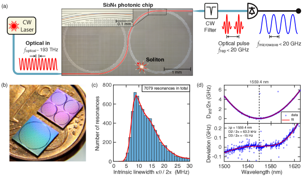
Principle and sample description: The principle of nanophotonic microwave synthesis based on integrated soliton microcombs is depicted in Fig. 1(a). A photonic integrated microresonator is driven by a near-infrared continuous-wave (CW) laser to produce an optical pulse stream, which upon photodetection generates a microwave signal, whose frequency depends on the microresonator FSR. As the soliton threshold power increases with decreasing FSR, the key challenge here is to generate soliton pulses with power levels compatible with integrated lasers Liang and Bowers (2010); Morton and Morton (2018). We overcome this challenge by using the recently developed photonic Damascene reflow process Pfeiffer et al. (2018a, b) to fabricate high-Q integrated microresonators based on ultralow-loss Si3N4 waveguides (linear propagation loss dB/m). Such low waveguide loss is achieved by using several key fabrication techniques, including deep-UV (DUV) stepper lithography based on KrF at 248 nm to pattern waveguides with reduced stitching errors and superior quality (see Methods), as well as stress-release patterns Pfeiffer et al. (2018a) to prevent cracks in the thick Si3N4 film required for strong anormalous GVD. In addition, to minimize the spatial mode coupling between the soliton mode and other waveguide modes, and to optimize Q, we design the microresonators in perfect ring shape, whose diameters are 2.30 (4.60) mm for 20 (10) GHz FSR. Figure 1(b) shows a photo of the final Si3N4 photonic chips in mm2 size, in comparison with a 1-cent Euro coin. Frequency-comb-assisted diode laser spectroscopy Del’Haye et al. (2009) is used to characterize the microresonator dispersion (defined as , where is the frequency of the -th resonance relative to the pump resonance , corresponds to the FSR, is the GVD and is the third-order dispersion) and resonance linewidth in the fundamental transverse electric (TE00) mode. For each resonance, the loaded linewidth , intrinsic loss , and coupling strength are extracted from each resonance fit. The resonance analysis method is described in Ref. Liu et al. (2016, 2018a). Figure 1(c) shows the histogram of of 7079 fitted resonances, from nine characterized 20-GHz-FSR samples. The most probable value is MHz, corresponding to a statistical intrinsic . Figure 1(d) shows the measured and outlines the resonance frequency deviation from a D2-dominant parabolic profile, defined as , in order to reveal mode crossings and the term. As evidenced by Fig. 1(d), our fabrication and design yield an ideal anomalous GVD with significantly reduced mode crossings compared with the previous works Johnson et al. (2012); Huang et al. (2015); Xuan et al. (2016). Details concerning chip input/output coupling and resonator coupling are found in Methods.
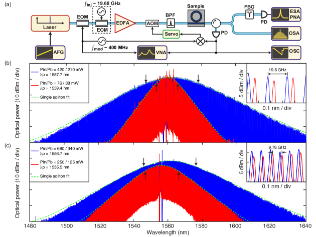
K- and X-band soliton generation: Using the Damascene reflow process, we fabricate microresonators of FSR in the microwave K- and X- band (sample information in Methods). Single solitons are generated using simple laser piezo frequency tuning Guo et al. (2016) in all tested samples. As shown in Fig. 2(b), in sample A (red), the single soliton is generated with 38 mW power in the bus waveguide on the chip (76 mW power in the input lensed fiber), while parametric oscillation is observed with 7 mW power. The single soliton spectrum fit shows a 3-dB-bandwidth of 11.0 nm, corresponding to a pulse duration of 232 fs. Not only is it the first Si3N4 single soliton of a K-band repetition rate, but it also represents an extremely low threshold power for soliton formation, on par with the power values in silica and crystalline microresonators Liang et al. (2015); Yang et al. (2018). This power level is compatible with state-of-art silicon-based lasers Liang and Bowers (2010); Morton and Morton (2018), which makes full integration of on-chip lasers and Si3N4 nonlinear microresonators possible Stern et al. (2018); Raja et al. (2019); Volet et al. (2018); Suh et al. (2019b), and allows for soliton-based microwave oscillators. In sample B, the single soliton is generated with 210 mW power, and features 170 comb lines within the 3-dB-bandwidth of 26.9 nm (94.6 fs pulse duration), ideal for creating dense wavelength-division multiplexing (WDM) channels for coherent communications Mazur et al. (2018). We further generate single solitons of 9.78 GHz repetition rate in the X-band, as shown in Fig. 2(c), with 125 mW power in sample C (red) and 340 mW power in sample D (blue). The 3-dB-bandwidths are 17.4 nm (red, 139 comb lines, 146 fs pulse duration) and 25.8 nm (blue, 327 comb lines, 98.6 fs pulse duration), respectively.
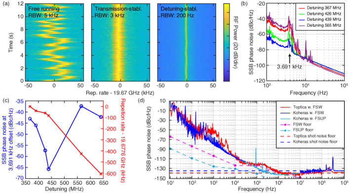
Phase noise characterization: Next, we perform a thorough analysis of the phase fluctuations of the photonically generated K-band microwave carrier. The measurement setup is shown in Fig 2(a): the soliton pulse stream is driven by a CW diode laser (Toptica CTL) and the soliton repetition rate is detected on a fast InGaAs photodetector whose output electrical signal is fed to a phase noise analyzer (PNA, Rohde Schwarz FSW43). First, the drift of the photodetected soliton repetition rate around 19.67 GHz is characterized in the free-running state. An oscillation at low frequency 5 Hz is observed, as shown in Fig. 3(a) left, which is likely caused by the unstable chip coupling using suspended lensed fibers, susceptible to vibrations. To mitigate this effect, an acousto-optic modulator (AOM) with a power servo based on a proportional-integral-derivative (PID) controller is used to stabilize the transmitted power through the chip, and compensate for the coupling fluctuations. The previously observed low-frequency oscillation is significantly reduced with stabilized transmitted power, as shown in Fig. 3(a) middle, which demonstrates that a more robust device coupling scheme is required to improve the soliton stability and the phase noise performance of the soliton-based microwave synthesizer.
The phase noise measurements with different cavity-pump detunings are performed with stabilized transmitted power, as shown in Fig. 3(b). The detuning is measured using a vector network analyser (VNA) to probe the resonance frequency relative to the laser Guo et al. (2016). A “quiet point” Yi et al. (2017), caused by mode crossings, is observed at the detuning of MHz, and provides the best phase noise performance compared with other detuning values. To evidence the phase noise reduction at the quiet point, the repetition rate shift and the phase noise value at 3.691 kHz Fourier offset frequency, where the laser phase noise exhibits a characteristic feature, are measured with different detunings, as shown in Fig. 3(c). Note that the quiet point may not be found in every (multi-)soliton state but that, in future works, its presence could be engineered (see Methods). The rest of our measurements are performed out of the quiet point regime.
To further stabilize the soliton-based microwave carrier, we actively stabilize the cavity-pump detuning using an offset sideband Pound-Drever-Hall (PDH) lock Stone et al. (2018) with feedback applied to the pump laser power, which can effectively compensate the cavity resonance jitter induced by coupling fluctuations. As shown in Fig. 3(a) (right), such detuning-stabilization also stabilizes the soliton repetition rate. Two cases are investigated: In case A, with the power-stabilization, the soliton is driven by a diode laser (Toptica) and the PNA used is the FSW43; In case B, with the detuning-stabilization, the soliton is driven by a fiber laser (Koheras AdjustiK), and, besides the FSW43, an additional PNA (Rohde Schwarz FSUP, with cross-correlations) is used only for measuring the 10 kHz - 1 MHz offset frequency range. Figure 3(d) shows the measured phase noise in both cases, as well as the PNA noise floors. In case A, the noise feature within 100 Hz – 10 kHz offset frequency is caused by the Toptica laser phase noise, while the step-like feature within 20 kHz – 1 MHz is caused by the FSW43 noise floor, which is the reason why the FSUP is needed to measure this frequency range in case B. Using Koheras with FSW43 and FSUP, case B shows a reduced phase noise, while the phase noise within 200 kHz – 10 MHz is marginally below the shot noise floor, likely caused by parasitic anti-correlation effects in FSUP Nelson et al. (2014). Our analysis shows that, in case B, the main phase noise limitation is the laser relative intensity noise (RIN) for offset frequencies MHz, with a contribution from the impact of the thermo-refractive noise (TRN) Huang et al. (2019) in Si3N4 on the detuning within 10 – 100 kHz offset frequencies (see Supplementary Information). The absolute single-sideband (SSB) phase noise power spectral density of the microwave carrier shows –80 dBc/Hz at 1 kHz offset Fourier frequency, –110 dBc/Hz at 10 kHz and –130 dBc/Hz at 100 kHz. Note that the phase noise is not measured precisely at a quiet point in case B, therefore further phase noise reduction is possible through quiet point operation (see Methods) and laser RIN reduction.
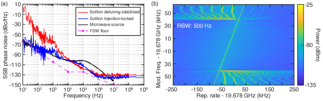
Soliton injection-locking: A variety of microwave photonic applications require long-term stability of microwave signals, represented as low phase noise at low offset frequency. In our work, the low soliton repetition rate achieved allows soliton injection-locking to an external microwave source Weng et al. (2019), which can discipline the soliton repetition rate and reduce the low-frequency phase noise. A modulation frequency swept around 19.678 GHz is applied on the CW pump laser, and the microwave spectrum evolution is shown in Fig. 4(b). The soliton injection-locking, i.e. synchronization of the soliton repetition rate to the modulation frequency , is observed when kHz. This injection-locking range is more than a 100-fold increase compared to that measured in MgF2 resonators ( Hz in Ref. Weng et al. (2019)), likely caused by the lower Q in Si3N4. The phase noise spectra of the injection-locked soliton (blue), the microwave source used (black), and the soliton with a stabilized cavity-pump detuning (red, as described previously), are compared in Fig. 4(a). The phase noise of the injection-locked soliton closely follows the microwave source’s phase noise at offset frequency below 10 kHz, apart from a residual bump at 1 kHz which originates from the pump laser. For Fourier offset frequencies above 10 kHz, the soliton-induced spectral purification effect is revealed, as the soliton phase noise departs from the injected microwave phase noise, and becomes similar to the case with only active cavity-pump detuning stabilization. This soliton injection-locking technique can provide extended coherence time for applications such as dual-comb spectroscopy, and allows for coherent combination of microcombs and further scaling of soliton pulse energy.
Conclusion:
We have demonstrated low-noise nanophotonic microwave synthesizers based on soliton microcombs that operate in the key microwave K- and X-band, with pump power levels compatible with integrated Si-based lasers Liang and Bowers (2010); Morton and Morton (2018).
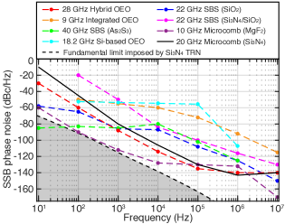
Figure 5 compares our work to other compact photonics-based microwave oscillators, as well as the fundamental limit of TRN in Si3N4. The measured phase noise in our work is still 30 dB higher than the fundamental limit of Si3N4 TRN (see Supplementary Information), revealing the considerable potential for further phase noise reduction, which can be accessed with improved quiet point operation, device coupling, RIN suppression, and higher Q.
Compared with other microwave oscillators shown in Fig. 5, our soliton-based microwave ocillators already show competitive phase noise levels, and represent a critical step towards fully integrated low-noise microwave oscillators for future architectures of radars and information processing networks. Moreover, the low soliton repetition rate achieved here is intrinsically beneficial for future dense WDM channel generation schemesMazur et al. (2018) and will greatly reduce the complexity of photonic integrated frequency synthesizers Spencer et al. (2018) and atomic clocks Newman et al. (2018), fostering wide deployment of these technologies in our information society.
Methods
DUV stepper lithography: The advantages of DUV stepper lithography over electron beam lithography (EBL), besides the higher yield and lower cost, are: 1. The stitching errors on the wafer are 4 or 5 times smaller than the ones on the reticle used in the industrial standard 4 or 5 demagnification lens systems; 2. The reticle writing using standard photolithography ( 1 hour) is much faster than the wafer writing using EBL (> 10 hours), thus the field-to-field (or stripe-to-stripe) time delay is significantly shorter with DUV than with EBL, leading to smaller stitching errors caused by the beam drift; 3. The field (or stripe) size of photolithography for reticle writing is much larger than the field size of EBL for wafer writing, leading to fewer stitching errors; 4. Multipass for reticle writing can be easily adapted with reasonable cost increases. Consequently, DUV stepper lithography can provide superior lithography quality, and has been used in recently demonstrated integrated Brillouin laser Gundavarapu et al. (2019) based on low-confinement Si3N4 waveguides of optical propagation loss below 1 dB/m Bauters et al. (2011); Spencer et al. (2014).
Sample information: More than 20 samples are tested and single solitons are generated in every sample. Only four selected samples (A, B, C and D) are shown here. Samples A and B are used to generate K-band solitons, as shown in Fig. 2(b). Sample A is undercoupled, with a loaded linewidth MHz and a coupling coefficient . Sample B is overcoupled, with MHz and . Samples C and D are used to generate X-band single soliton, as shown in Fig. 2(c). Sample C is critically coupled, with MHz and . Sample D is overcoupled, with MHz and . The waveguide cross-sections, width height, are nm2 for samples A and B, and nm2 for sample C and D, respectively. The Raman self-frequency-shift Karpov et al. (2016); Yi et al. (2016) is observed of nm in sample B and of nm in sample D. For K-band single soliton generation, further power budget reduction to below 100 mW input requires a higher microresonator Q factor, and may also be achieved by increasing the anomalous GVD () via e.g. coupled resonators exhibiting mode hybridization Kim et al. (2017), which increases the soliton pulse duration and CW-to-soliton power conversion efficiency.
Coupling scheme: The microresonator is coupled to a multi-mode bus waveguide of the same cross-section for high coupling ideality Pfeiffer et al. (2017). Both the straight and pulley bus waveguides are studied in this work, however no prominent performance difference is observed, likely due to the high Q. Light is coupled into and out of the chip device via double-inverse nanotapers Liu et al. (2018b). The coupling loss is 3 dB per facet, corresponding to 25 fiber-chip-fiber coupling efficiency.
Quiet point measurement: At the quiet point with the detuning MHz, the Raman self-frequency-shift Karpov et al. (2016); Yi et al. (2016), which is the soliton center frequency shift according to ( is the Raman shock term), is compensated by the recoil caused by a mode-crossing-induced dispersive wave Yang et al. (2016), such that . The quiet point is reflected on the repetition rate stability since . This point gives the best phase noise performance compared with other detuning values. However, we emphasize that a quiet point can be engineered via the third-order dispersion that skews the soliton spectrum and leads to a repetition rate shift with detuning Cherenkov et al. (2017), such that
| (1) |
Thus the dependence of the repetition rate on the detuning could be mitigated over a broader bandwidth based on a more reliable effect (via ) than mode crossings.
Funding Information: This work was supported by Contract FA9550-19-C-7001 (KECOMO) from the Defense Advanced Research Projects Agency (DARPA), Microsystems Technology Office (MTO), by the Air Force Office of Scientific Research, Air Force Material Command, USAF under Award No. FA9550-15-1-0099, and by Swiss National Science Foundation under grant agreement No. 176563 (BRIDGE).
Acknowledgments: The authors thank Nils J. Engelsen, Guanhao Huang and Wenle Weng for the fruitful discussion. E.L. and M.K. acknowledge the support from the European Space Technology Centre with ESA Contract No. 4000116145/16/NL/MH/GM and 4000118777/16/NL/GM, respectively. J.H. acknowledges the support provided by Prof. Hwa-Yaw Tam and from the General Research Fund of the Hong Kong Government under project PolyU 152207/15E. H.G. acknowledges the support from the European Union’s Horizon 2020 research and innovation program under Marie Sklodowska-Curie IF grant agreement No. 709249. The Si3N4 microresonator samples were fabricated in the EPFL center of MicroNanoTechnology (CMi).
Author contribution: J.L. designed and fabricated the Si3N4 samples, with the assistance from R.N.W and H.G.. Samples were characterized and analyzed by J.L. and J.H.. A.S.R., J.L., J.H. and M.K. performed the soliton generation experiment. E.L., A.S.R., J.R. and R.B. performed the phase noise measurement and the soliton injection-locking experiment. J.L., R.B., E.L. and T.J.K. wrote the manuscript, with the input from others. T.J.K. supervised the project.
Data Availability Statement: The code and data used to produce the plots within this work will be released on the repository Zenodo upon publication of this preprint.
References
- Capmany and Novak (2007) J. Capmany and D. Novak, Nature Photonics 1, 319 (2007).
- Marpaung et al. (2019) D. Marpaung, J. Yao, and J. Capmany, Nature Photonics 13, 80 (2019).
- Supradeepa et al. (2012) V. Supradeepa, C. M. Long, R. Wu, F. Ferdous, E. Hamidi, D. E. Leaird, and A. M. Weiner, Nature Photonics 6, 186 (2012).
- Ghelfi et al. (2014) P. Ghelfi, F. Laghezza, F. Scotti, G. Serafino, A. Capria, S. Pinna, D. Onori, C. Porzi, M. Scaffardi, A. Malacarne, V. Vercesi, E. Lazzeri, F. Berizzi, and A. Bogoni, Nature 507, 341 (2014).
- Ataie et al. (2015) V. Ataie, D. Esman, B.-P. Kuo, N. Alic, and S. Radic, Science 350, 1343 (2015).
- Temprana et al. (2015) E. Temprana, E. Myslivets, B.-P. Kuo, L. Liu, V. Ataie, N. Alic, and S. Radic, Science 348, 1445 (2015).
- Xie et al. (2016) X. Xie, R. Bouchand, D. Nicolodi, M. Giunta, W. Hänsel, M. Lezius, A. Joshi, S. Datta, C. Alexandre, M. Lours, P.-A. Tremblin, G. Santarelli, R. Holzwarth, and Y. Le Coq, Nature Photonics 11, 44 (2016).
- Kippenberg et al. (2018) T. J. Kippenberg, A. L. Gaeta, M. Lipson, and M. L. Gorodetsky, Science 361 (2018), 10.1126/science.aan8083.
- Gaeta et al. (2019) A. L. Gaeta, M. Lipson, and T. J. Kippenberg, Nature Photonics 13, 158 (2019).
- Moss et al. (2013) D. J. Moss, R. Morandotti, A. L. Gaeta, and M. Lipson, Nature Photonics 7, 597 (2013).
- Weng et al. (2019) W. Weng, E. Lucas, G. Lihachev, V. E. Lobanov, H. Guo, M. L. Gorodetsky, and T. J. Kippenberg, Phys. Rev. Lett. 122, 013902 (2019).
- Liang and Bowers (2010) D. Liang and J. E. Bowers, Nature Photonics 4, 511 (2010).
- Morton and Morton (2018) P. A. Morton and M. J. Morton, J. Lightwave Technol. 36, 5048 (2018).
- Mazur et al. (2018) M. Mazur, M.-G. Suh, A. Fülöp, J. Schröder, V. Torres-Company, M. Karlsson, K. J. Vahala, and P. A. Andrekson, arXiv 1812.11046 (2018).
- Spencer et al. (2018) D. T. Spencer, T. Drake, T. C. Briles, J. Stone, L. C. Sinclair, C. Fredrick, Q. Li, D. Westly, B. R. Ilic, A. Bluestone, N. Volet, T. Komljenovic, L. Chang, S. H. Lee, D. Y. Oh, M.-G. Suh, K. Y. Yang, M. H. P. Pfeiffer, T. J. Kippenberg, E. Norberg, L. Theogarajan, K. Vahala, N. R. Newbury, K. Srinivasan, J. E. Bowers, S. A. Diddams, and S. B. Papp, Nature 557, 81 (2018).
- Newman et al. (2018) Z. L. Newman, V. Maurice, T. E. Drake, J. R. Stone, T. C. Briles, D. T. Spencer, C. Fredrick, Q. Li, D. Westly, B. R. Ilic, B. Shen, M.-G. Suh, K. Y. Yang, C. Johnson, D. M. S. Johnson, L. Hollberg, K. Vahala, K. Srinivasan, J. K. S. A. Diddams and, S. B. Papp, and M. T. Hummon, arXiv 1811.00616v1 (2018).
- Hecht (2016) J. Hecht, Nature News 536, 139 (2016).
- Khilo et al. (2012) A. Khilo, S. J. Spector, M. E. Grein, A. H. Nejadmalayeri, C. W. Holzwarth, M. Y. Sander, M. S. Dahlem, M. Y. Peng, M. W. Geis, N. A. DiLello, J. U. Yoon, A. Motaledi, J. S. Orcutt, J. P. Wang, C. M. Sorace-Agaskar, M. A. Popovic, J. Sun, G.-R. Zhou, H. Byun, J. Chen, J. L. Hoyt, H. I. Smith, R. J. Ram, M. Perrott, T. M. Lyszczarz, E. P. Ippen, and F. X. Kartner, Optics Express 20, 4454 (2012).
- Lim et al. (2010) C. Lim, A. Nirmalathas, M. Bakaul, P. Gamage, K.-L. Lee, Y. Yang, D. Novak, and R. Waterhouse, Journal of Lightwave Technology 28, 390 (2010).
- Khan et al. (2010) M. H. Khan, H. Shen, Y. Xuan, L. Zhao, S. Xiao, D. E. Leaird, A. M. Weiner, and M. Qi, Nature Photonics 4, 117 (2010).
- Riehle (2017) F. Riehle, Nature Photonics 11, 25 (2017).
- Rappaport et al. (2011) T. S. Rappaport, J. N. Murdock, and F. Gutierrez, Proceedings of the IEEE 99, 1390 (2011).
- Li et al. (2014) J. Li, X. Yi, H. Lee, S. A. Diddams, and K. J. Vahala, Science 345, 309 (2014).
- Liang et al. (2015) W. Liang, D. Eliyahu, V. S. Ilchenko, A. A. Savchenkov, A. B. Matsko, D. Seidel, and L. Maleki, Nature Communications 6, 7957 (2015).
- Udem et al. (2002) T. Udem, R. Holzwarth, and T. W. Hänsch, Nature 416, 233 (2002).
- Cundiff and Ye (2003) S. T. Cundiff and J. Ye, Rev. Mod. Phys. 75, 325 (2003).
- Torres-Company and Weiner (2014) V. Torres-Company and A. M. Weiner, Laser & Photonics Reviews 8, 368 (2014).
- Wu et al. (2018) J. Wu, X. Xu, T. G. Nguyen, S. T. Chu, B. E. Little, R. Morandotti, A. Mitchell, and D. J. Moss, IEEE Journal of Selected Topics in Quantum Electronics 24, 1 (2018).
- Stern et al. (2018) B. Stern, X. Ji, Y. Okawachi, A. L. Gaeta, and M. Lipson, Nature 562, 401 (2018).
- Raja et al. (2019) A. S. Raja, A. S. Voloshin, H. Guo, S. E. Agafonova, J. Liu, A. S. Gorodnitskiy, M. Karpov, N. G. Pavlov, E. Lucas, R. R. Galiev, A. E. Shitikov, J. D. Jost, M. L. Gorodetsky, and T. J. Kippenberg, Nature Communications 10, 680 (2019).
- Marin-Palomo et al. (2017) P. Marin-Palomo, J. N. Kemal, M. Karpov, A. Kordts, J. Pfeifle, M. H. P. Pfeiffer, P. Trocha, S. Wolf, V. Brasch, M. H. Anderson, R. Rosenberger, K. Vijayan, W. Freude, T. J. Kippenberg, and C. Koos, Nature 546, 274 (2017).
- Trocha et al. (2018) P. Trocha, M. Karpov, D. Ganin, M. H. P. Pfeiffer, A. Kordts, S. Wolf, J. Krockenberger, P. Marin-Palomo, C. Weimann, S. Randel, W. Freude, T. J. Kippenberg, and C. Koos, Science 359, 887 (2018).
- Suh and Vahala (2018) M.-G. Suh and K. J. Vahala, Science 359, 884 (2018).
- Obrzud et al. (2019) E. Obrzud, M. Rainer, A. Harutyunyan, M. H. Anderson, J. Liu, M. Geiselmann, B. Chazelas, S. Kundermann, S. Lecomte, M. Cecconi, A. Ghedina, E. Molinari, F. Pepe, F. Wildi, F. Bouchy, T. J. Kippenberg, and T. Herr, Nature Photonics 13, 31 (2019).
- Suh et al. (2019a) M.-G. Suh, X. Yi, Y.-H. Lai, S. Leifer, I. S. Grudinin, G. Vasisht, E. C. Martin, M. P. Fitzgerald, G. Doppmann, J. Wang, D. Mawet, S. B. Papp, S. A. Diddams, C. Beichman, and K. Vahala, Nature Photonics 13, 25 (2019a).
- Dutt et al. (2018) A. Dutt, C. Joshi, X. Ji, J. Cardenas, Y. Okawachi, K. Luke, A. L. Gaeta, and M. Lipson, Science Advances 4 (2018), 10.1126/sciadv.1701858.
- Yang et al. (2019) Q.-F. Yang, B. Shen, H. Wang, M. Tran, Z. Zhang, K. Y. Yang, L. Wu, C. Bao, J. Bowers, A. Yariv, and K. Vahala, Science 363, 965 (2019).
- Marchand et al. (2019) P. J. Marchand, J.-J. Ho, M. H. Pfeiffer, J. Liu, C. Hauger, T. Lasser, and T. J. Kippenberg, arXiv 1902.06985 (2019).
- (39) X. Ji, A. Klenner, X. Yao, Y. Gan, A. L. Gaeta, C. P. Hendon, and M. Lipson, arXiv 1902.07695.
- Yang et al. (2018) K. Y. Yang, D. Y. Oh, S. H. Lee, Q.-F. Yang, X. Yi, B. Shen, H. Wang, and K. Vahala, Nature Photonics 12, 297 (2018).
- Johnson et al. (2012) A. R. Johnson, Y. Okawachi, J. S. Levy, J. Cardenas, K. Saha, M. Lipson, and A. L. Gaeta, Opt. Lett. 37, 875 (2012).
- Huang et al. (2015) S. W. Huang, J. Yang, J. Lim, H. Zhou, M. Yu, D. L. Kwong, and C. W. Wong, Scientific Reports 5, 13355 (2015).
- Xuan et al. (2016) Y. Xuan, Y. Liu, L. T. Varghese, A. J. Metcalf, X. Xue, P.-H. Wang, K. Han, J. A. Jaramillo-Villegas, A. A. Noman, C. Wang, S. Kim, M. Teng, Y. J. Lee, B. Niu, L. Fan, J. Wang, D. E. Leaird, A. M. Weiner, and M. Qi, Optica 3, 1171 (2016).
- Li et al. (2017) Q. Li, T. C. Briles, D. A. Westly, T. E. Drake, J. R. Stone, B. R. Ilic, S. A. Diddams, S. B. Papp, and K. Srinivasan, Optica 4, 193 (2017).
- Stone et al. (2018) J. R. Stone, T. C. Briles, T. E. Drake, D. T. Spencer, D. R. Carlson, S. A. Diddams, and S. B. Papp, Phys. Rev. Lett. 121, 063902 (2018).
- Pfeiffer et al. (2018a) M. H. P. Pfeiffer, C. Herkommer, J. Liu, T. Morais, M. Zervas, M. Geiselmann, and T. J. Kippenberg, IEEE Journal of Selected Topics in Quantum Electronics, IEEE Journal of Selected Topics in Quantum Electronics 24, 1 (2018a).
- Pfeiffer et al. (2018b) M. H. P. Pfeiffer, J. Liu, A. S. Raja, T. Morais, B. Ghadiani, and T. J. Kippenberg, Optica 5, 884 (2018b).
- Del’Haye et al. (2009) P. Del’Haye, O. Arcizet, M. L. Gorodetsky, R. Holzwarth, and T. J. Kippenberg, Nature Photonics 3, 529 (2009).
- Liu et al. (2016) J. Liu, V. Brasch, M. H. P. Pfeiffer, A. Kordts, A. N. Kamel, H. Guo, M. Geiselmann, and T. J. Kippenberg, Opt. Lett. 41, 3134 (2016).
- Liu et al. (2018a) J. Liu, A. S. Raja, M. Karpov, B. Ghadiani, M. H. P. Pfeiffer, B. Du, N. J. Engelsen, H. Guo, M. Zervas, and T. J. Kippenberg, Optica 5, 1347 (2018a).
- Guo et al. (2016) H. Guo, M. Karpov, E. Lucas, A. Kordts, M. H. P. Pfeiffer, V. Brasch, G. Lihachev, V. E. Lobanov, M. L. Gorodetsky, and T. J. Kippenberg, Nature Physics 13, 94 (2016).
- Volet et al. (2018) N. Volet, X. Yi, Q. Yang, E. J. Stanton, P. A. Morton, K. Y. Yang, K. J. Vahala, and J. E. Bowers, Laser Photonics Rev. 0, 1700307 (2018).
- Suh et al. (2019b) M.-G. Suh, C. Y. Wang, C. Johnson, and K. J. Vahala, Opt. Lett. 44, 1841 (2019b).
- Yi et al. (2017) X. Yi, Q.-F. Yang, X. Zhang, K. Y. Yang, X. Li, and K. Vahala, Nature Communications 8, 14869 (2017).
- Nelson et al. (2014) C. W. Nelson, A. Hati, and D. A. Howe, Review of Scientific Instruments 85, 024705 (2014).
- Huang et al. (2019) G. Huang, E. Lucas, J. Liu, A. S. Raja, G. Lihachev, M. L. Gorodetsky, N. J. Engelsen, and T. J. Kippenberg, arXiv 1901.07112v1 (2019).
- Tang et al. (2018) J. Tang, T. Hao, W. Li, D. Domenech, R. B. nos, P. M. noz, N. Zhu, J. Capmany, and M. Li, Opt. Express 26, 12257 (2018).
- Merklein et al. (2016) M. Merklein, B. Stiller, I. V. Kabakova, U. S. Mutugala, K. Vu, S. J. Madden, B. J. Eggleton, and R. Slavík, Opt. Lett. 41, 4633 (2016).
- T.Do et al. (2019) P. T.Do, C. Alonso-Ramos, X. L. Roux, I. Ledoux, B. Journet, and E. Cassan, arXiv 1903.01137 (2019).
- Li et al. (2013) J. Li, H. Lee, and K. J. Vahala, Nature Communications 4, 2097 (2013).
- Gundavarapu et al. (2019) S. Gundavarapu, G. M. Brodnik, M. Puckett, T. Huffman, D. Bose, R. Behunin, J. Wu, T. Qiu, C. Pinho, N. Chauhan, J. Nohava, P. T. Rakich, K. D. Nelson, M. Salit, and D. J. Blumenthal, Nature Photonics 13, 60 (2019).
- Bauters et al. (2011) J. F. Bauters, M. J. R. Heck, D. D. John, J. S. Barton, C. M. Bruinink, A. Leinse, R. G. Heideman, D. J. Blumenthal, and J. E. Bowers, Opt. Express 19, 24090 (2011).
- Spencer et al. (2014) D. T. Spencer, J. F. Bauters, M. J. R. Heck, and J. E. Bowers, Optica 1, 153 (2014).
- Karpov et al. (2016) M. Karpov, H. Guo, A. Kordts, V. Brasch, M. H. P. Pfeiffer, M. Zervas, M. Geiselmann, and T. J. Kippenberg, Phys. Rev. Lett. 116, 103902 (2016).
- Yi et al. (2016) X. Yi, Q.-F. Yang, K. Y. Yang, and K. Vahala, Opt. Lett. 41, 3419 (2016).
- Kim et al. (2017) S. Kim, K. Han, C. Wang, J. A. Jaramillo-Villegas, X. Xue, C. Bao, Y. Xuan, D. E. Leaird, A. M. Weiner, and M. Qi, Nature Communications 8, 372 (2017).
- Pfeiffer et al. (2017) M. H. P. Pfeiffer, J. Liu, M. Geiselmann, and T. J. Kippenberg, Phys. Rev. Applied 7, 024026 (2017).
- Liu et al. (2018b) J. Liu, A. S. Raja, M. H. P. Pfeiffer, C. Herkommer, H. Guo, M. Zervas, M. Geiselmann, and T. J. Kippenberg, Opt. Lett. 43, 3200 (2018b).
- Yang et al. (2016) Q.-F. Yang, X. Yi, K. Y. Yang, and K. Vahala, Optica 3, 1132 (2016).
- Cherenkov et al. (2017) A. V. Cherenkov, V. E. Lobanov, and M. L. Gorodetsky, Phys. Rev. A 95, 033810 (2017).