Broadband space-time wave packets propagating 70 m
Abstract
The propagation distance of a pulsed beam in free space is ultimately limited by diffraction and space-time coupling. ‘Space-time’ (ST) wave packets are pulsed beams endowed with tight spatio-temporal spectral correlations that render them propagation-invariant. Here we explore the limits of the propagation distance for ST wave packets. Making use of a specially designed phase plate inscribed by gray-scale lithography, we synthesize a ST light sheet of width m and bandwidth nm and confirm a propagation distance of m.
‘Space-time’ (ST) wave packets are pulsed beams that propagate in linear materials without diffraction or dispersion Sõnajalg and Saari (1996); Saari and Reivelt (1997); Reivelt and Saari (2000); Sheppard (2002); Porras et al. (2003); Di Trapani et al. (2003); Zapata-Rodríguez and Porras (2006); Faccio et al. (2007); Clerici et al. (2008); Bonaretti et al. (2009); Turunen and Friberg (2010); Hernández-Figueroa et al. (2014) by virtue of tight spatio-temporal correlations introduced into their spectra Donnelly and Ziolkowski (1993); Longhi (2004); Saari and Reivelt (2004). In contrast, the behavior of the more familiar monochromatic diffraction-free beams (e.g., Bessel, Mathieu, and Weber beams Levy et al. (2016)) stems from their particular spatial profiles. In an ST wave packet, each spatial frequency is associated with one temporal frequency (or wavelength) Kondakci and Abouraddy (2016); Parker and Alonso (2016), which is enforced through spatio-temporal structuring of the field; for example, via a spatial light modulator (SLM) Kondakci and Abouraddy (2017). Guided by this principle, we have recently synthesized a wide variety of ST wave packets, including non-accelerating Airy wave packets Kondakci and Abouraddy (2018a), tilted-pulse-front wave packets Kondakci et al. (2019), wave packets with group velocities tuned in free space from to ( is the speed of light in vacuum) Kondakci and Abouraddy (2018b) or that travel in optical materials at Bhaduri et al. (2019), incoherent diffraction-free fields Yessenov et al. (2019a), in addition to confirming their self-healing Kondakci and Abouraddy (2018c).
What is the maximum distance that a ST wave packet can travel before the onset of substantial diffractive spreading? Previous realizations of ST wave packets have been limited to centimeter-scale distances. Our recent demonstration of a ST wave packet synthesized via a SLM that propagated for 6 m Bhaduri et al. (2018) motivates investigating their ultimate propagation limit. We have recently shown theoretically that the maximum propagation distance of a ST wave packet is determined by its two internal degrees of freedom Kondakci et al. (2018a); Yessenov et al. (2019b): (1) the spectral uncertainty, which is the unavoidable ‘fuzziness’ in the association between the spatial frequencies and wavelengths; and (2) the spectral tilt angle, which characterizes the curvature of the spatio-temporal spectral correlations and determines the wave-packet group velocity. The technical limitations of SLMs (e.g., the relatively small active area and large pixel size) pose significant obstacles to improving the spectral uncertainty. Moreover, SLMs have low energy-handling capabilities and are not available in all spectral bands. To overcome these limitations, one may utilize instead phase plates. We have used such a phase plate to synthesize broadband (bandwidth nm) and narrowband ( nm) ST wave packets of spatial width m propagating for mm Kondakci et al. (2018b).
Here we exploit a lithographically inscribed phase plate to synthesize a ST wave packet of bandwidth nm that propagates for a record m by optimizing its spatio-temporal structure. The source is a Ti:Sa-based amplified femtosecond laser system at a wavelength of nm. Furthermore, we confirm the high laser-damage threshold of the phase plate. A theoretical model and numerical simulations provide a guide for extending this strategy to even longer propagation distances for ST wave packets, potentially on the few-kilometer-scale. Our findings pave the way for the use of ST wave packets in applications ranging from remote sensing to directed energy.
We start by considering a traditional pulsed beam , where is the slowly varying envelope, is the center frequency, and is the corresponding wave number. The spatio-temporal spectrum , which is the two-dimensional Fourier transform of , must lie on the surface of the light-cone Donnelly and Ziolkowski (1993); Kondakci and Abouraddy (2017). The central requirement for synthesizing ST wave packets is to impose the spatio-temporal spectral constraint , which produces an envelope having the form
| (1) |
which is a wave packet undergoing rigid translation along without diffraction or dispersion at a group velocity Yessenov et al. (2018). This ideal constraint results in a dimensional reduction of the spatio-temporal spectrum , where is the one-dimensional Fourier transform of and is the temporal frequency associated with each spatial frequency . In the spatio-temporal spectral space , this constraint corresponds to a spectral hyperplane that is parallel to the -axis and makes an angle (the spectral tilt angle) with respect to the -axis. Therefore, the reduced-dimensionality spatio-temporal spectrum of the ST wave packet in Eq. 1 lies along the conic section at the intersection of the light-cone with . The projection of this spatio-temporal spectrum onto the -plane is a straight line whose slope is the group velocity along the propagation axis Kondakci and Abouraddy (2017); Saari (2018); Yessenov et al. (2018); Kondakci and Abouraddy (2018b); Bhaduri et al. (2019).
Such ideal ST wave packets are infinite-energy pulses. We have recently shown Yessenov et al. (2019b) that realistic finite-energy ST wave packets display spectral uncertainty in the association between the spatial and temporal frequencies such that the delta-function spectral correlation is replaced by , where is a narrow spectral function of width (the spectral uncertainty). The validity of this decomposition requires only that be smaller than the bandwidth . It can be shown that such a ST wave packet is the product of an ideal ST wave packet traveling at a group velocity and a broad uncertainty-induced ‘pilot envelope’ of width traveling at a group velocity . The maximum propagation distance is thus determined by the temporal walk-off between the ideal ST wave packet and the pilot envelope Yessenov et al. (2019b),
| (2) |
This is a surprising result: is not dictated by the beam size or the pulse width; instead, only by the internal degrees of freedom of the ST wave packet: the spectral uncertainty and the spectral tilt angle .
Increasing thus requires reducing both and the term ; i.e., (). If , where , then at nm we have:
| (3) |
where is the spectral uncertainty on the wavelength scale. For example, if pm and , as realized in Bhaduri et al. (2018) using a diffraction grating of width 25 mm and setting via a SLM, we have m.
The impact of the beam size enters indirectly as follows. The temporal and spatial bandwidths of a ST wave packet, and , respectively, are related through , where Kondakci and Abouraddy (2016, 2017); Yessenov et al. (2018). If , then and thus , where is in radians. Therefore, for a fixed bandwidth , increasing (increasing ) requires reducing and thus increasing the beam width. One may alternatively maintain the beam size but increase the bandwidth . Counter-intuitively, shorter wave packets travel longer when the internal degrees of freedom and are held fixed.
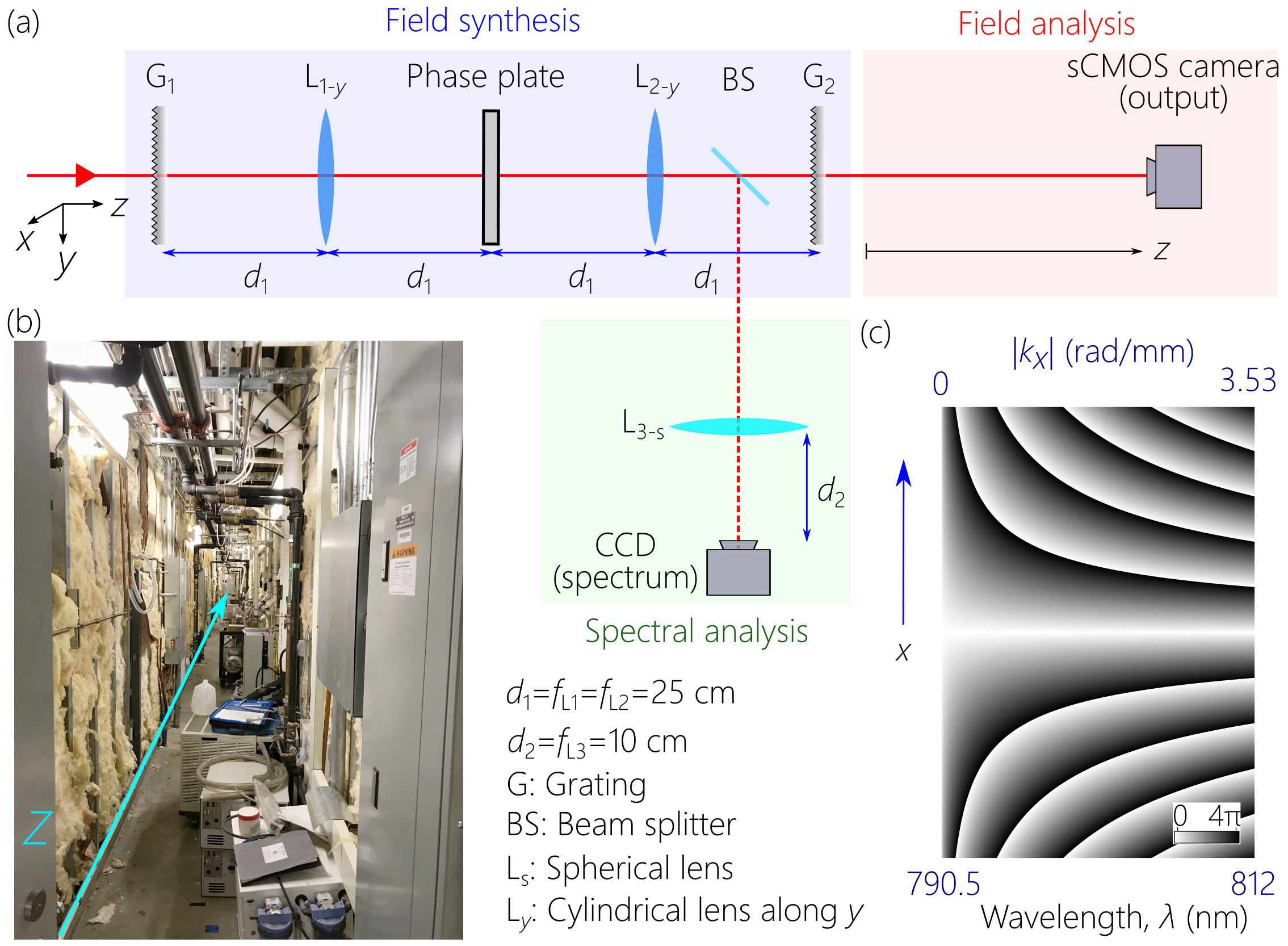
In the experiment we report here, we designed a phase plate that introduces spatio-temporal correlations into the field spectrum corresponding to with nm. This may appear too restrictive a target for practical realization. However, is not an angle in physical space, but a measure of the curvature of the spatio-temporal spectrum. As shown in Bhaduri et al. (2018), it is straightforward to create correlations in which approaches . The phase plate utilized was fabricated using a gray-scale lithography technique McKenna et al. (2010), whereupon positive-tone photoresist (S1813, MicroChem) Shi was spin-coated on a RCA-cleaned, double-side polished 2-inch-diameter soda lime glass wafer at 1000 rpm for 60 s followed by baking in an oven at C for 30 min. A laser-pattern-generator (Heidelberg Instruments) Hei was used to write the design. The exposed sample was then developed in AZ solution AZ for 35 s followed by DI water rinse. A calibration step was performed on a different sample (prepared with the same process conditions), before writing the design to determine the depth of the photoresist at a particular gray level after development. The details of the calibration process are discussed elsewhere Mohammad et al. (2017, 2018). The phase distribution realized by this plate is plotted in Fig. 1(c).
The femtosecond laser source utilized here is the Multi-Terawatt Femtosecond Laser (MTFL) Webb et al. (2014); Webb (2016) housed at the University of Central Florida. This Ti:Sa-based chirped pulse amplification system consists of 3 stages of amplification and is capable of delivering 500-mJ-energy pulses at a wavelength of nm and spectral bandwidth of nm, corresponding to pulses having a width of fs (FWHM) at a repetition rate of 10 Hz. The beam used in this experiment was extracted directly from the regenerative amplifier (first stage of amplification) at an energy of only 1 mJ, which was further attenuated to avoid saturating the detectors.
The experimental set-up for synthesizing and characterizing ST wave packets is shown in Fig. 1(a). The MTFL laser is first expanded spatially to a diameter of mm and is incident at an angle of on a reflective diffraction grating G1 (1800 lines/mm, mm2) that disperses the femtosecond pulses along the -direction. The first diffraction order is collimated and directed through a cylindrical lens L1-y (oriented along the -direction in a configuration) to the phase-plate that introduces the requisite spatio-temporal spectral correlations between and . Each column of the phase plate modulates a particular by imparting a linearly varying phase along the direction orthogonal to the -direction and whose slope corresponds to the value of the associated . The transmitted wave front is reconstituted into a pulse by a symmetrically placed lens L2-y and grating G2 (1800 lines/mm, mm2) to produce the ST light sheet. All the lenses and mirrors had dimensions of at least 50 mm, except for the phase plate whose dimensions were mm2.
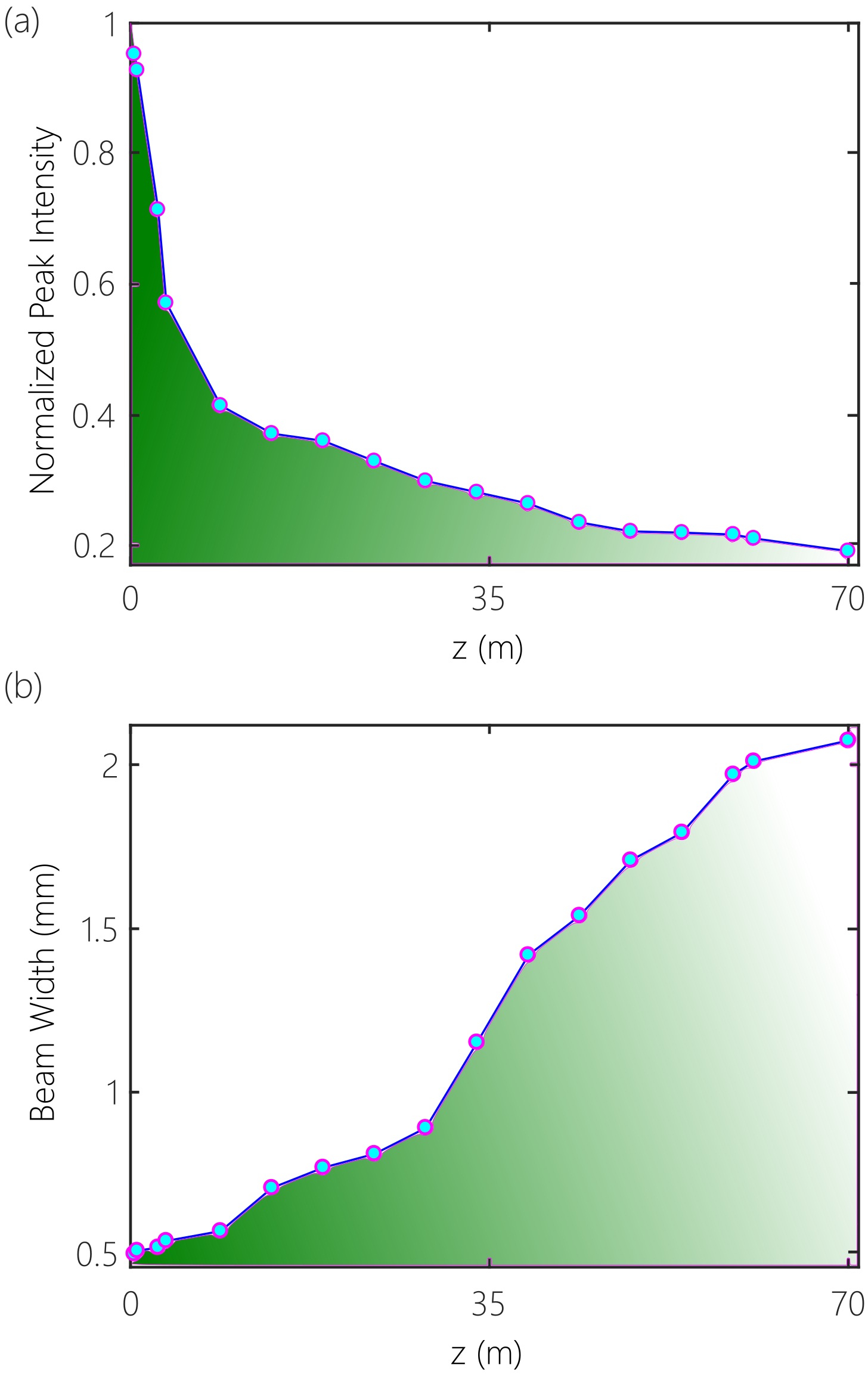
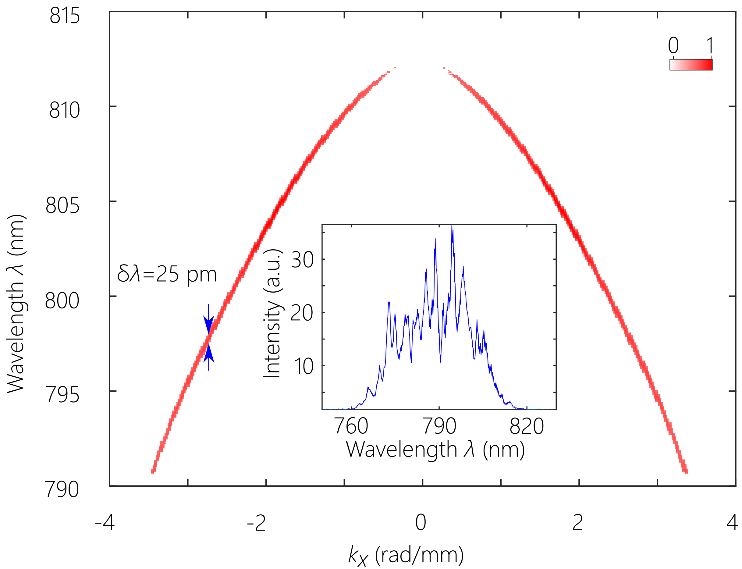
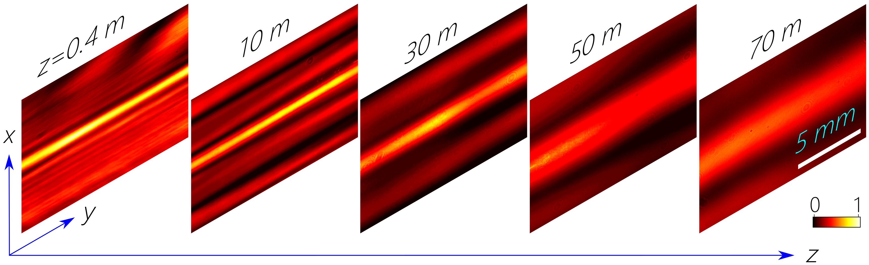
The ST wave packet is then directed by mirrors out of the laboratory to follow a straight path down a service chase that cuts across the CREOL building for observation [Fig. 1(b)]. A sCMOS camera (Andor, Zyla) is scanned along the -axis to record the time-averaged intensity of the ST light sheet every 5 m, and a CCD camera (The Imaging Source, DMK 72AUC02) records the spatio-temporal spectrum after performing a spatial Fourier transform via a spherical lens L3-s Kondakci and Abouraddy (2017, 2018a); Kondakci et al. (2018b); Bhaduri et al. (2018); see Fig. 2. Images of the time-averaged beam intensity in the transverse plane at different distances along the propagation direction are shown in Fig. 3 (exposure time of each is 25 msec) and the axial evolution of the beam width and the peak intensity at the beam center are plotted in Fig. 4.
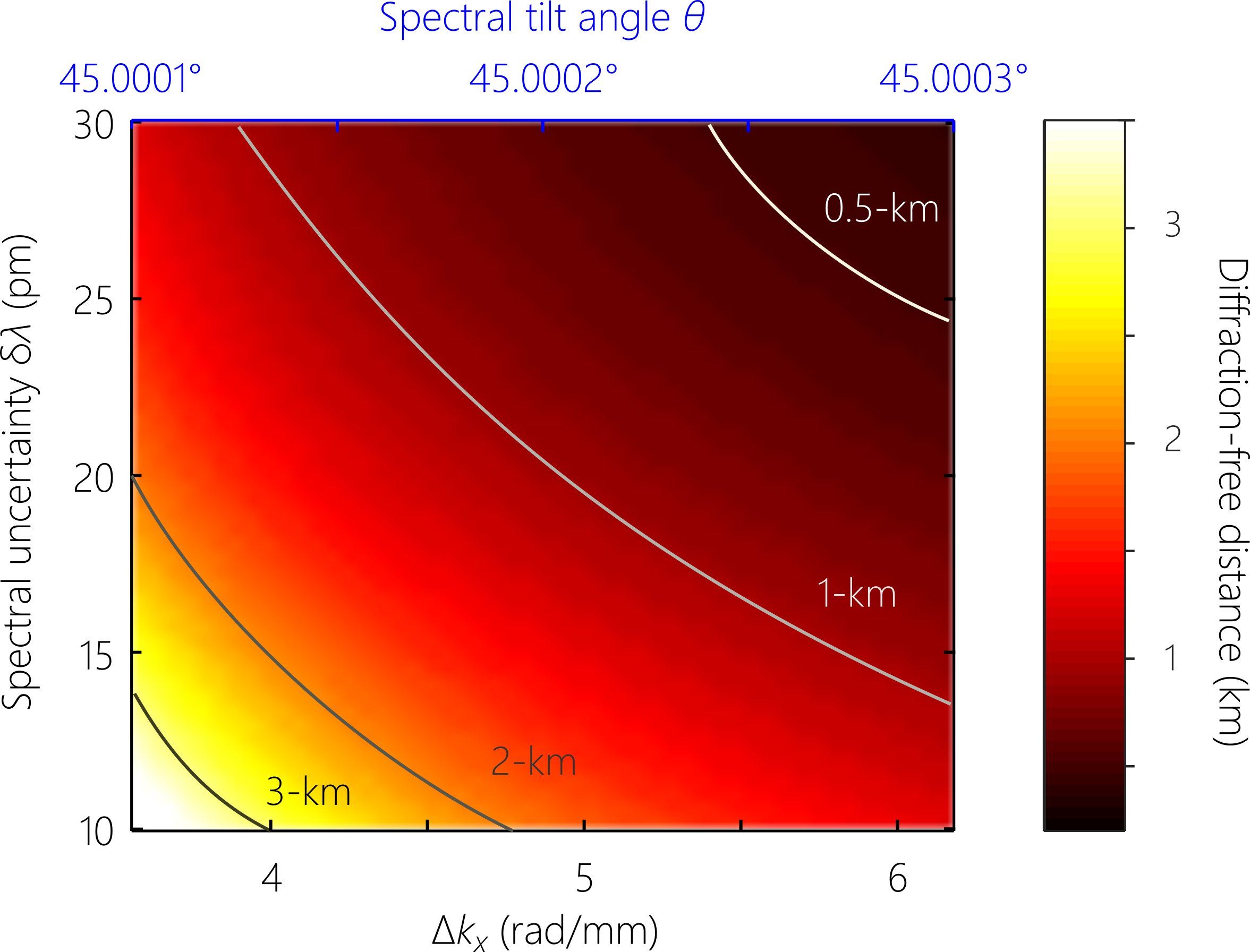
The Rayleigh range of a Gaussian beam of width 700 m at a wavelength of 800 nm is cm, such that here. However, it can be shown that the ratio is on the order of (the ratio of the full bandwidth to the spectral uncertainty) Yessenov et al. (2019b), which in our experiment is . We therefore predict that the same configuration can produce ST wave packets that may propagate for km. In moving forward, we have found that spatial filtering of the input laser or increasing the initial beam size at the diffraction grating is critical. Secondly, utilizing a 50-mm-wide phase plate is critical for producing beams propagating larger distances. We provide in Fig. 5 a numerical calculation of the propagation distance for ST wave packets while varying and . The results are in accordance with the rule of thumb in Eq. 3 and show clearly that reducing the spectral uncertainty to pm and reaching a spectral tilt angle of enables us to reach km with a beam width of mm and bandwidth nm.
The phase plate laser-damage threshold was assessed by slowly increasing the incident fluence until instantaneous white-light damage was observed. The pulse energy of the MTFL output beam was adjusted to 10 mJ and, and the 25.4-mm-diameter beam was directed to the phase plate via a lens having m. The lens is initially placed in proximity to the phase plate and then gradually moved further away until damage was observed. From these parameters we calculate the beam size at the phase plate and thence the fluence damage threshold, which was thus determined to be 584 mJ/cm2.
The ST wave packets presented here are in the form of a light sheet with the field uniform along one transverse dimension as a result of correlating the wavelengths with the spatial frequencies along alone. Future work will focus on extending our approach to both transverse coordinates and thus producing wave packets in the form of a needle with higher local intensities. Because ST wave packets are an example of extending the concept of ‘classical entanglement’ from discretized degrees of freedom (e.g., polarization and spatial modes) Qian and Eberly (2011); Kagalwala et al. (2013) to continuous degrees of freedom (time and space) Kondakci et al. (2018a), localizing the field in both transverse coordinates along with time represents an extension to classical entanglement between three continuous degrees of freedom.
In conclusion, we have synthesized a ST wave packet of bandwidth nm in the form of a light sheet of width m that propagates in free space for a distance of m. The requisite spatio-temporal correlations are introduced into the field spectrum via a specially designed phase plate fabricated via gray-scale lithography. We have presented theoretical estimates and numerical calculations that indicate the potential for extending the propagation distance to the few-kilometer range with improvements to the current experiment.
Funding
U.S. Office of Naval Research (ONR) (N00014-17-1-2458); U.S. Office of Naval Research (ONR) (N66001-10-1-4065); U.S. Army Research Office (ARO) MURI program on Light Filamentation Science (W911NF1110297); HEL JTO (FA9550-11-1-0001).
References
- Sõnajalg and Saari (1996) H. Sõnajalg and P. Saari, Opt. Lett. 21, 1162 (1996).
- Saari and Reivelt (1997) P. Saari and K. Reivelt, Phys. Rev. Lett. 79, 4135 (1997).
- Reivelt and Saari (2000) K. Reivelt and P. Saari, J. Opt. Soc. Am. A 17, 1785 (2000).
- Sheppard (2002) C. J. R. Sheppard, J. Opt. Soc. Am. A 19, 2218 (2002).
- Porras et al. (2003) M. A. Porras, I. Gonzalo, and A. Mondello, Phys. Rev. E 67, 066604 (2003).
- Di Trapani et al. (2003) P. Di Trapani, G. Valiulis, A. Piskarskas, O. Jedrkiewicz, J. Trull, C. Conti, and S. Trillo, Phys. Rev. Lett. 91, 093904 (2003).
- Zapata-Rodríguez and Porras (2006) C. J. Zapata-Rodríguez and M. A. Porras, Opt. Lett. 31, 3532 (2006).
- Faccio et al. (2007) D. Faccio, A. Averchi, A. Couairon, M. Kolesik, J. Moloney, A. Dubietis, G. Tamosauskas, P. Polesana, A. Piskarskas, and P. D. Trapani, Opt. Express 15, 13077 (2007).
- Clerici et al. (2008) M. Clerici, D. Faccio, A. Lotti, E. Rubino, O. Jedrkiewicz, J. Biegert, and P. D. Trapani, Opt. Express 16, 19807 (2008).
- Bonaretti et al. (2009) F. Bonaretti, D. Faccio, M. Clerici, J. Biegert, and P. Di Trapani, Opt. Express 17, 9804 (2009).
- Turunen and Friberg (2010) J. Turunen and A. T. Friberg, Prog. Opt. 54, 1 (2010).
- Hernández-Figueroa et al. (2014) H. E. Hernández-Figueroa, E. Recami, and M. Zamboni-Rached, eds., Non-diffracting Waves (Wiley-VCH, 2014).
- Donnelly and Ziolkowski (1993) R. Donnelly and R. Ziolkowski, Proc. R. Soc. Lond. A 440, 541 (1993).
- Longhi (2004) S. Longhi, Opt. Express 12, 935 (2004).
- Saari and Reivelt (2004) P. Saari and K. Reivelt, Phys. Rev. E 69, 036612 (2004).
- Levy et al. (2016) U. Levy, S. Derevyanko, and Y. Silberberg, Prog. Opt. 61, 237 (2016).
- Kondakci and Abouraddy (2016) H. E. Kondakci and A. F. Abouraddy, Opt. Express 24, 28659 (2016).
- Parker and Alonso (2016) K. J. Parker and M. A. Alonso, Opt. Express 24, 28669 (2016).
- Kondakci and Abouraddy (2017) H. E. Kondakci and A. F. Abouraddy, Nat. Photon. 11, 733 (2017).
- Kondakci and Abouraddy (2018a) H. E. Kondakci and A. F. Abouraddy, Phys. Rev. Lett. 120, 163901 (2018a).
- Kondakci et al. (2019) H. E. Kondakci, N. S. Nye, D. N. Christodoulides, and A. F. Abouraddy, ACS Photonics , in press (2019).
- Kondakci and Abouraddy (2018b) H. E. Kondakci and A. F. Abouraddy, arXiv:1810.08893 (2018b).
- Bhaduri et al. (2019) B. Bhaduri, M. Yessenov, and A. F. Abouraddy, Optica 6, in press (2019).
- Yessenov et al. (2019a) M. Yessenov, H. E. Kondakci, M. Meem, R. Menon, and A. F. Abouraddy, unpublished (2019a).
- Kondakci and Abouraddy (2018c) H. E. Kondakci and A. F. Abouraddy, Opt. Lett. 43, 3830 (2018c).
- Bhaduri et al. (2018) B. Bhaduri, M. Yessenov, and A. F. Abouraddy, Opt. Express 26, 20111 (2018).
- Kondakci et al. (2018a) H. E. Kondakci, M. A. Alonso, and A. F. Abouraddy, arxiv:1812.10566 (2018a).
- Yessenov et al. (2019b) M. Yessenov, L. Mach, B. Bhaduri, D. Mardani, H. E. Kondakci, G. A. Atia, M. A. Alonso, and A. F. Abouraddy, arxiv:1901.00538 (2019b).
- Kondakci et al. (2018b) H. E. Kondakci, M. Yessenov, M. Meem, D. Reyes, D. Thul, S. R. Fairchild, M. Richardson, R. Menon, and A. F. Abouraddy, Opt. Express 26, 13628 (2018b).
- Yessenov et al. (2018) M. Yessenov, B. Bhaduri, H. E. Kondakci, and A. F. Abouraddy, arXiv:1809.08375 (2018).
- Saari (2018) P. Saari, Phys. Rev. A 97, 063824 (2018).
- McKenna et al. (2010) C. McKenna, K. Walsh, M. Crain, and J. Lake, 2010 18th Biennial University/Government/Industry Micro/Nano Symposium (2010).
- (33) “Data sheet of Shipley 1813 photoresist,” http://www.microchem.com/PDFs_Dow/S1800.pdf.
- (34) “Data sheet of Heidelberg PG 101,” http://www.himt.de/index.php/upg-101.html.
- (35) “Data sheet of AZ developer,” http://www.microchemicals.com/micro/az_developer.pdf.
- Mohammad et al. (2017) N. Mohammad, M. Meem, X. Wan, and R. Menon, Sci. Rep. 7, 5789 (2017).
- Mohammad et al. (2018) N. Mohammad, M. Meem, B. Shen, P. Wang, and R. Menon, Sci. Rep. 8, 2799 (2018).
- Webb et al. (2014) B. Webb, J. Bradford, K. Lim, N. Bodnar, A. Vaupel, E. Mckee, M. Baudelet, M. Durand, L. Shah, and M. Richardson, in CLEO: 2014 (Optical Society of America, 2014) p. SM1F.6.
- Webb (2016) B. Webb, Design and Engineering of Ultrafast Amplification Systems, Ph.D. thesis, University of Central Florida (2016).
- Qian and Eberly (2011) X.-F. Qian and J. H. Eberly, Opt. Lett. 36, 4110 (2011).
- Kagalwala et al. (2013) K. H. Kagalwala, G. Di Giuseppe, A. F. Abouraddy, and B. E. A. Saleh, Nat. Photon. 7, 72 (2013).