Coupled dynamics of magnetizations in spin-Hall oscillators via spin current injection
Abstract
An array of spin torque oscillators (STOs) for practical applications such as pattern recognition was recently proposed, where several STOs are connected by a common nonmagnet. In this structure, in addition to the electric and/or magnetic interactions proposed in previous works, the STOs are spontaneously coupled to each other through the nonmagnetic connector, due to the injection of spin current. Solving the Landau-Lifshitz-Gilbert equation numerically for such system consisting of three STOs driven by the spin Hall effect, it is found that both in-phase and antiphase synchronization of the STOs can be achieved by adjusting the current density and appropriate distance between the oscillators.
Index Terms:
spintronics, spin Hall effect, spin torque oscillator, synchronization, Landau-Lifshitz-Gilbert equationI Introduction
An excitation of a mutually coupled motion of the magnetizations in nanostructured ferromagnets, such as synchronization between spin torque oscillators (STOs) [1-15], has attracted much attention from the viewpoints of both fundamental physics and practical applications such as phased arrays and brain-inspired computing [16,17]. The mechanism of the synchronization in the previous works was based on the electric and/or magnetic interactions among STOs, such as spin wave propagation, current injection, microwave application, and dipole interaction.
Spintronics devices have another possibility to excite a coupled dynamics of magnetizations by an injection of spin current. For example, the coupled motion of two ferromagnets in ferromagnetic resonance through spin pumping was studied previously [18-20]. Recently, we studied a synchronization of self-oscillations between STOs by the injection of spin current [21]. The system we considered was similar to an array of STOs proposed by Kudo and Morie for pattern recognition [17], where several STOs driven by the spin Hall effect [22-27] are connected by a common nonmagnetic electrode. Note that a self-oscillation in each STO is excited when a spin current is injected from a nonmagnetic heavy metal into the free layer of the STO. We noticed that the spin current simultaneously creates spin accumulation inside the free layer. When the free layers of the STOs are connected by a nonmagnet having a long spin diffusion length, another spin current flows in the connector, in accordance with the gradient of the spin accumulation. This additional spin current excites additional spin torques on the magnetizations, and leads to a coupled motion of the magnetizations. Considering two STOs, we showed that this type of coupling results in an antiphase synchronization of the magnetizations. The result indicates a possibility to excite a spontaneous synchronization between STOs without using electric and/or magnetic interactions. It is of interest accordingly to extend the system to a large number of STOs.
In this paper, theoretical investigation is given for the phase dynamics between three STOs driven by the spin Hall effect. It is found that two of three STOs show phase synchronizations, whereas the other STO shows an oscillation with a different frequency. An antiphase synchronization between two STOs is found for a relatively large-coupling case. For a relatively weak coupling case, on the other hand, the antiphase synchronization appears for a small current region, whereas the phase difference becomes an in-phase for a large current region.
II System description
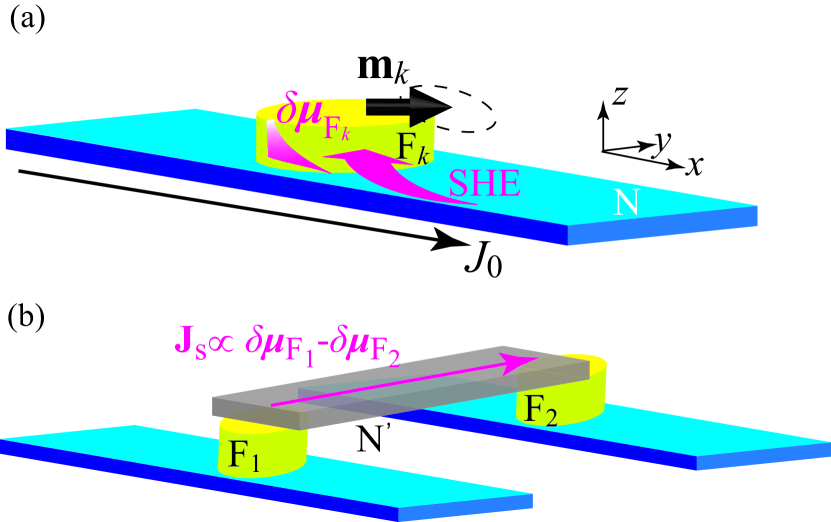
The basic idea of the coupling mechanism between STOs is as follow, where is the number of the oscillators. Each oscillator consists of a ferromagnet and a nonmagnetic heavy metal placed at the bottom. We use suffixes such as to distinguish the ferromagnets Fk. Electric current densities along the -direction are applied to all of the bottom nonmagnet. The ferromagnet is placed onto the nonmagnet along the -direction, as shown in Fig. 1(a). According to the experiment [28], we assume that the internal magnetic field of the ferromagnet Fk consists of an in-plane anisotropy field along the -direction and a demagnetization field along the -direction as
| (1) |
where is the unit vector pointing in the magnetization direction of the Fk layer. The magnetic energy density of the ferromagnet is given by . The energetically stable states correspond to .
The spin Hall effect in the bottom nonmagnet injects pure spin current having the spin polarization along the -direction into the Fk layer, and excites the spin torque
| (2) |
where , , and are the gyromagnetic ratio, saturation magnetization, and thickness of the ferromagnet, respectively. An effective spin Hall angle, including the interface mixing conductance, is denoted as [13]. The spin torque given by Eq. (2) induces a self-oscillation of the magnetization around the -direction [28]. We note that the pure spin current generated from the bottom nonmagnet simultaneously creates the spin accumulation in the Fk layer, which obeys the diffusion equation [25,29] and is given by [30]
| (3) |
Here, [21] depends on the conductivity and spin-diffusion length , where we use the suffixes F and N to distinguish the quantities related to the ferromagnet and nonmagnet, respectively. The thickness of the bottom nonmagnet is . The pure spin Hall angle in the nonmagnet and the spin polarization of the conductivity in the ferromagnet are and , respectively. The quantity is related to the F/N interface resistance, whereas with the F/N cross section area is defined as [30]. The origin of the axis locates at the F/N interface.
Now let us consider a coupling between the ferromagnets. We note that the spin accumulation given by Eq. (3) depends on the magnetization direction. Therefore, even when all the ferromagnets have the same magnetic properties and are under the effect of the same current densities, the spin accumulations in the ferromagnets are different when the magnetizations point to different directions. When the top surfaces of two ferromagnets, Fk and F, are connected by an additional nonmagnet N′, as shown in Fig. 1(b), another spin current flows in the connector according to the gradient of the spin accumulation . When the spin-diffusion length of the connector is sufficiently longer than its dimensional length , the spin current in the top connector flowing from the Fk to F layer is given by
| (4) |
where is the conductivity of the top connector. The emission of the spin current given by Eq. (4) from the Fk/N′ interface results in an excitation of an additional spin torque acting on given by
| (5) |
where we use Eqs. (3) and (4). We introduce as
| (6) |
Using Eqs. (2) and (5), the Landau-Lifshitz-Gilbert equation of the magnetization is given by
| (7) |
where is the Gilbert damping constant. We should note that the coupling torque in Eq. (7) results in a coupled motion of the magnetizations because it depends on the magnetization directions in the other ferromagnets. For a system consisting of two () STOs, it was shown that this coupling torque leads to an antiphase synchronization of the magnetizations [21]. However, a coupled dynamics between STOs for has not been investigated yet.
III Synchronization of three STOs
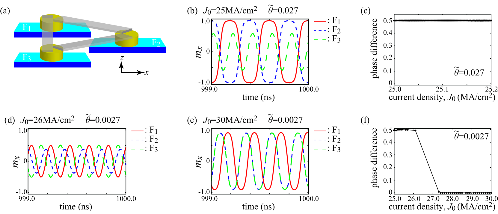
We study the coupled motion of the magnetizations by solving Eq. (7) numerically. It has been revealed in the field of nonlinear science that even the behavior of a small number of identical oscillators is rather complex [31]. For example, for three oscillators arranged in a ring coupled through electric interaction, three stable synchronous states are possible, depending on the coupling strength [32]. In our case, we note that the coupling strength depends on the distance between the ferromagnets. This fact means that the maximum number of the oscillators to connect all of them by the same coupling strength in two-dimensional space is three. Therefore, we consider the case of , and assume that each ferromagnet is located at the vertex of an equilateral triangle. Figure 2(a) shows a possible alignment of the STOs.
The material parameters are derived from recent experiments on the spin Hall magnetoresistance in W/CoFeB metallic bilayer [33] and first-principles calculations [34] as emu/c.c., Oe, rad/(Oe s), , nm, and . The value of the coupling strength, , for nm was estimated to be by assuming that N′ consists of Cu [21]. In this paper, we also study the case of a weak coupling, . We note that, in the absence of the coupling, the self-oscillation in an STO is excited when the current density is in the range of [35], where
| (8) |
| (9) |
The critical current density is the minimum current density necessary to destabilize the magnetization staying near the easy axis and excites self-oscillation. On the other hand, is the switching current density to reverse the magnetization direction between two stable states. The values of and are 26 and 33 MA/cm2, respectively. We, however, emphasize that these values are defined for a single STO. The current densities determining the oscillation range are mainly determined by the effective spin Hall angle but are slightly affected by the coupling constant , as shown below.
Figure 2(b) shows an example of the coupled motion of the magnetizations for a relatively strong coupling strength and MA/cm2. Here, the oscillations of the -components of () in a steady state are shown by different lines. We see that the magnetizations in two STOs show the antiphase synchronization, whereas the magnetization in the other STO shows a self-oscillation with a different frequency. For example, in Fig. 2(b), the magnetizations in F1 (red solid) and F2 (blue dotted) layers are antiphase-coupled. On the other hand, the magnetization in F3 (green dashed) layer shows an oscillation with a frequency which is higher than that of F1 and F2 layers. We note that which of three STOs are coupled depend on the initial conditions of the magnetizations. The phase difference between the coupled STOs is, however, independent from which of STOs are coupled. It should be emphasized that the antiphase synchronization of two STOs appear even for different values of the current. Figure 2(c) summarizes the current dependence of the phase difference between coupled STOs, where and in the vertical axis correspond to the in-phase and antiphase, respectively [13]. It shows that the antiphase synchronization between two STOs appears for the current range of MA/cm2. We find that the magnetizations relax to the stable state near the initial state for MA/cm2, whereas they switch to the other stable state for MA/cm2. Also it should be noticed here that the current range of the self-oscillation is significantly suppressed by the coupling torque.
We also investigate a coupled motion of the magnetizations for a relatively weak coupling strength, . Be reminded that the coupling strength can be adjusted by changing the distance between the STOs, as can be seen from Eq. (6). Figures 2(d) and 2(e) show examples of the magnetization oscillations for and MA/cm2, respectively. For MA/cm2, two magnetizations show an antiphase synchronization, whereas the other magnetization oscillate with a different frequency. This behavior is similar to the result shown in Fig. 2(b). On the other hand, for MA/cm2, two magnetizations show an in-phase synchronization, i.e., the magnetizations in F2 and F3 layers oscillate with the same phases. Figure 2(f) summarizes the current dependence of the phase difference between coupled STOs, indicating that the antiphase synchronization is stabilized in a relatively small current region whereas the in-phase synchronization appears in a relatively large current region.
An in-phase synchronization between oscillators is useful to enhance the emission power from devices such as microwave generator and magnetic sensor. On the other hand, an antiphase synchronization, or more generally, out-of-phase synchronization, can be used in practical devices such as phased array and pattern recognition [17,36-40]. Therefore, a precise control of the phases between STOs is of interest in applied physics. The result shown in Fig. 2(f) indicates a possibility to control the phase difference between the magnetizations in a spin Hall geometry by adjusting the current density and choosing an appropriate distance between the STOs.
IV Summary
In conclusion, theoretical investigation is carried out in a coupled motion of three magnetizations in a spin Hall geometry. The ferromagnets are coupled to each other through the injection of spin current by connecting the top surfaces of the free layers with nonmagnets having long spin diffusion lengths. For a relatively strong coupling case, two magnetizations showed an antiphase synchronization whereas the other magnetization oscillated with a different frequency. The current range of the self-oscillation was significantly suppressed compared with the case of free running. For a relatively weak coupling case, on the other hand, the phase difference between two STOs depended on the current magnitude. The antiphase synchronization appeared when the current was small, whereas an in-phase synchronization was found in the large current region. The results indicate a possibility to achieve a precise control of the phases in the STOs by adjusting the current density and choosing an appropriate distance between them.
Acknowledgement
This work was supported by JSPS KAKENHI Grant-in-Aid for Young Scientists (B) 16K17486. The author is grateful grateful to Y. Kawamura, S. Tsunegi, T. Yorozu, and H. Kubota for valuable discussions. The author is also thankful to S. Iba, A. Spiesser, H. Maehara, and A. Emura for their support and encouragement.
References
- [1] S. Kaka, M. R. Pufall, W. H. Rippard, T. J. Silva, S. E. Russek, and J. A. Katine, ”Mutual phase-locking of microwave spin torque nano-oscillators”, Nature vol. 437, 389, 2005.
- [2] F. B. Mancoff, N. D. Rizzo, B. N. Engel, and S. Tehrani, ”Phase-locking in double-point-contact spin-transfer devices”, Nature vol. 437, 393, 2005.
- [3] J. Grollier, V. Cros, and A. Fert, ”Synchronization of spin-transfer oscillators driven by stimulated microwave currents”, Phys. Rev. B, vol. 73, 060409, 2006.
- [4] K. Kudo, R. Sato, and K. Mizushima, ”Synchronized Magnetization Oscillations in F/N/F Nanopillars”, Jpn. J. Appl. Phys. vol. 45, 3869, 2006.
- [5] B. Georges, J. Grollier, V. Cros, and A. Fert, ”Impact of the electrical connection of spin transfer nano-oscillators on their synchronization: an analytical study”, Appl. Phys. Lett. vol. 92, 232504, 2008.
- [6] A. Slavin and V. Tiberkevich, ”Nonlinear Auto-Oscillator Theory of Microwave Generation by Spin-Polarized Current”, IEEE. Trans. Magn. vol. 45, 1875, 2009.
- [7] D. Li, Y. Zhou, B. Hu, J. Akerman, and C. Zhou, ”Multiple synchronization attractors of serially connected spin-torque oscillators”, Phys. Rev. B vol. 86, 014418, 2012.
- [8] S. Sani, J. Persson, S. M. Mohseni, Ye Pogoryelov, P. K. Muduli, A. Eklund, G. Malm, M. Käll, A. Dmitriev, and J. Akerman, ”Mutually synchronized bottom-up multi-nanocontact spin-torque oscillators”, Nat. Commun. vol. 4, 2731, 2013.
- [9] J. Turtle, K. Beauvais, R. Shaffer, A. Palacios, V. In, T. Emery, and P. Longhini, ”Gluing bifurcations in coupled spin torque nano-oscillators”, J. Appl. Phys. vol. 113, 114901, 2013.
- [10] N. Locatelli, A. Hamadeh, F. A. Araujo, A. D. Belanovsky, P. N. Skirdkov, R. Lebrun, V. V. Naletov, K. A. Zvezdin, M. Munoz, J. Grollier, O. Klein, V. Cros, and G. de Loubens, ”Efficient Synchronization of Dipolarly Coupled Vortex-Based Spin Transfer Nano-Oscillators”, Sci. Rep. vol. 5, 17039, 2015.
- [11] T. Kendziorczyk and T. Kuhn, ”Mutual synchronization of nanoconstriction-based spin Hall nano-oscillators through evanescent and propagating spin waves”, Phys. Rev. B vol. 93, 134413, 2016.
- [12] A. A. Awad, P. Dürrenfeld, A. Houshang, M. Dvornik, E. Iacoca, R. K. Dumas, and J. Akerman, ”Long-range mutual synchronization of spin Hall nano-oscillators”, Nat. Phys. vol. 13, 292, 2017.
- [13] T. Taniguchi, ”Dynamic coupling of ferromagnets via spin Hall magnetoresistance”, Phys. Rev. B vol. 95, 104426, 2017.
- [14] J. Turtle, P.-L. Buono, A. Palacios, C. Dabrowski, V. In, and P. Longhini, ”Synchronization of spin torque nano-oscillators”, Phys. Rev. B vol. 95, 144412, 2017.
- [15] T. Taniguchi, S. Tsunegi, and H. Kubota, ”Mutual synchronization of spin-torque oscillators consisting of perpendicularly magnetized free layers and in-plane magnetized pinned layers”, Appl. Phys. Express vol. 11, 013005, 2018.
- [16] J. Grollier, D. Querlioz, and M. D. Stiles, ”Spintronic Nanodevices for Bioinspired Computing”, Proc. IEEE vol. 104, 2024, 2016.
- [17] K. Kudo and T. Morie, ”Self-feedback electrically coupled spin-Hall oscillator array for pattern-matching operation”, Appl. Phys. Express vol. 10, 043001, 2017.
- [18] Y. Tserkovnyak, A. Brataas, and G. E. W. Bauer, ”Dynamic exchange coupling and Gilbert damping in magnetic multilayers”, J. Appl. Phys. vol. 93, 7534, 2003.
- [19] B. Heinrich, Y. Tserkovnyak, G. Woltersdorf, A. Brataas, R. Urban, and G. E. W. Bauer, ”Dynamic Exchange Coupling in Magnetic Bilayers”, Phys. Rev. Lett. vol. 90, 187601, 2003.
- [20] S. Takahashi, ”Giant enhancement of spin pumping in the out-of-phase precession mode”, Appl. Phys. Lett. vol. 104, 052407, 2014.
- [21] T. Taniguchi (submitted).
- [22] M. I. Dyakonov and V. I. Perel, ”Current-induced spin orientation of electrons in semiconductors”, Phys. Lett. A vol. 35, 459, 1971.
- [23] J. E. Hirsch, ”Spin Hall Effect”, Phys. Rev. Lett. vol. 83, 1834, 1999.
- [24] Y. K. Kato, R. C. Myers, A. C. Gossard, and D. D. Awschalom, ”Observation of the Spin Hall Effect in Semiconductors”, Science vol. 306, 1910, 2004.
- [25] S. Takahashi and S. Maekawa, ”Spin Current in Metals and Superconductors”, J. Phys. Soc. Jpn. vol. 77, 031009, 2008.
- [26] W. M. Saslow, ”Spin Hall effect and irreversible thermodynamics: Center-to-edge transverse current-induced voltage”, Phys. Rev. B vol. 91, 014401, 2015.
- [27] T. Taniguchi, ”Joule heating in spin Hall geometry”, Appl. Phys. Express vol. 9, 073005, 2016.
- [28] L. Liu, C.-F. Pai, D. C. Ralph, and R. A. Buhrman, ”Magnetic Oscillations Driven by the Spin Hall Effect in 3-Terminal Magnetic Tunnel Junction Devices”, Phys. Rev. Lett. vol. 91, 186602, 2012.
- [29] T. Valet and A. Fert, ”Theory of the perpendicular magnetoresistance in magnetic multilayers”, Phys. Rev. B vol. 48, 7099, 1993.
- [30] T. Taniguchi, ”Magnetoresistance generated from charge-spin conversion by anomalous Hall effect in metallic ferromagnetic/nonmagnetic bilayers”, Phys. Rev. B vol. 94, 174440, 2016.
- [31] A. Pikovsky, M. Rosenblum, and J. Kurths, ”Synchronization: A universal concept in nonlinear sciences” (Cambridge University Press, 2003), 1st ed.
- [32] P. S. Landa, ”Self-Oscillations in Systems with Finite Number of Degrees of Freedom” Moscow, Russia: Nauka, 1980.
- [33] J. Kim, P. Sheng, S. Takahashi, S. Mitani, and M. Hayashi, ”Spin Hall Magnetoresistance in Metallic Bilayers”, Phys. Rev. Lett. vol. 116, 097201, 2016.
- [34] M. Zwierzycki, Y. Tserkovnyak, P. J. Kelly, A. Brataas, and G. E. W. Bauer, ”First-principles study of magnetization relaxation ehnacement and spin transfer in thin magnetic films”, Phys. Rev. B vol. 71, 064420, 2005.
- [35] T. Taniguchi, Y. Utsumi, M. Marthaler, D. S. Golubev, and H. Imamura, ”Spin torque switching of an in-plane magnetized system in a thermally activated region”, Phys. Rev. B vol. 87, 054406, 2013.
- [36] E. Vassilieva, G. Pinto, J. A. de Barros, and P. Suppes, ”Learning Pattern Recognition Through Quasi-Synchronization of Phase Oscillators”, IEEE Trans. Neural. Netw. vol. 22, 84, 2011.
- [37] J. Sun, E. Timurdogan, A Yaacobi, E. S. Hosseini, and M. R. Watts, ”Large-scale nanophotonic phased array”, Nature vol. 493, 195, 2013.
- [38] P. Maffezzoni, B. Bahr, Z. Zhang, and L. Daniel, ”Oscillator Array Models for Associative Memory and Pattern Recognition”, IEEE Trans. Circuits. Syst. I-Regul. Pap. vol. 62, 159, 2015.
- [39] D. Nikonov, G. Csba, W. Porod, T. Shibata, D. Voils, D. Hammerstrom, I. A. Young, and G. I. Bourianoff, ”Coupled-Oscillator Associative Memory Array Operation for Patter Recognition”, IEEE J. Exploratory Solid. Stat. Comput. Devices. Circuits. vol. 1, 85, 2015.
- [40] A. Kumar and P. Mohanty, ”Autoassociative Memory and Patter Recognition in Microchemical Oscillator Network”, Sci. Rep. vol. 7, 411, 2017.