Model predictive control for transient frequency
regulation
of power networks
Abstract
This paper introduces a control strategy to simultaneously achieve asymptotic stabilization and transient frequency regulation of power networks. The control command is generated by iteratively solving an open-loop control cost minimization problem with stability and transient frequency constraints. To deal with the non-convexity of the stability constraint, we propose a convexification strategy that uses a reference trajectory based on the system’s current state. We also detail how to employ network partitions to implement the proposed control strategy in a distributed way, where each region only requires system information from neighboring regions to execute its controller.
keywords:
Power network stability, transient frequency, distributed control, model predictive control, convexification.1 Introduction
To maintain system security and integrity (Kundur et al., 2004), power networks are required to operate around their nominal frequencies in the presence of disturbances, and recover synchronization as disturbances disappear. However, such a transient frequency requirement faces fundamental challenges due to the deeper frequency nadir caused by higher penetration of renewable generators with lower inertia (Milano et al., 2018; Fang et al., 2018). This motivates our focus here on developing methods to actively attenuate transient frequency deviations while preserving network synchronization.
Literature review: Work in (Chiang, 2011; Dörfler et al., 2013) investigates power network synchronization conditions and their relations to system dynamics and initial conditions. However, such ideal conditions face challenges in practical scenarios with desired safe limits that transient frequencies may violate. On the other hand, various control schemes have been proposed to enhance transient frequency behavior, including power dispatch (Alam and Makram, 2006), power system stabilizer (Kundur, 1994), feedback linearization excitation (Mahmud et al., 2014), and virtual inertial placement (Borsche et al., 2015). Nonetheless, these strategies do not provide guarantees that the transient frequency will only evolve within safe limits. To address this point, our previous work (Zhang and Cortés, 2019) has combined Lyapunov stability and invariance analysis to propose a distributed controller simultaneously guaranteeing synchronization and transient frequency safety; however, the proposed controller does not actively forecast the disturbance evolution and its impact on transient frequency. As a result, it might result in significant control efforts that could otherwise have been avoided if the control action had been exerted earlier, something we address here through a model predictive control (MPC) architecture. A related body of work (Venkat et al., 2008; Mayne et al., 2000; Jia and Krogh, 2002) looks at reducing control effort while respecting performance requirements, and investigates distributed MPC for networked systems. However, the proposed distributed implementations may jeopardize network stability. Particularly, Jia and Krogh (2002) treats each subsystem as an independent system by considering the effect of other subsystems as bounded uncertainty, which complicates obtaining stability guarantees for the whole system. In fact, Venkat et al. (2008) show that, if each subsystem has no knowledge of other subsystems’ cost functions (Camponogara et al., 2002), this leads to a noncooperative game, and the control input trajectory may even diverge. In addition, some MPC approaches (Venkat et al., 2008; Nazari et al., 2014) restrict the predicted horizon to a single step in order to obtain distributed strategies, since otherwise the control signal may require global state or global system parameter information.
Statement of contribution: This paper develops a distributed receding-horizon control strategy that is able to simultaneously maintain local asymptotic stability of the system and regulate transient frequency. Specifically, for any given bus of interest, a safe frequency region is both invariant and attractive under the proposed design. For each state, we first formulate a non-convex finite-horizon open-loop optimal control problem whose solution is the control trajectory minimizing the overall cost under stability and transient frequency constraints. We then propose a reference trajectory technique for convexification. The centralized closed-loop control signal for each state is defined as the first-step solution of the optimal control problem. To enable distributed control, we partition the network into different regions and apply the centralized control for each region, while taking into account the dynamics of transmission lines connecting different regions. The resulting control signal for each bus only relies on system information of the region to which the bus belongs to and its neighboring regions.
2 Problem statement
In this section we introduce the model for the power network dynamics and state the control goals111We use the following notation. , , , and denote the set of natural, real, positive, and nonnegative real numbers, resp. Variables are assumed to belong to Euclidean space if not specified otherwise. Let and be the vector of all ones and zeros, resp. Denote as the boundary of a set . We let denote the ceiling operator and denote the 2-norm on . For any , let . For and , the saturation function is if and , if and , and otherwise. For , denotes its th entry and for , and denote its th row and th element. We denote by and its unique Moore-Penrose pseudoinverse and column space, resp. . Consider a power network described by a connected undirected graph, cf. (Bullo et al., 2009), , where is the collection of buses and is the collection of transmission lines. For each node , let , , and denote its inertia, damping coefficient, shifted voltage frequency relative to the nominal frequency, and active power injection, resp. Note that we explicitly allow some buses to have zero inertia, and we assume that at least one bus possesses strictly positive inertia. For compactness, define , , and . For each edge with vertices , , an orientation consists of choosing one node, say , to be the positive end of and the other vertex, , to be the negative end. Let be the incidence matrix corresponding to the chosen orientation (i.e., if is the positive end of , if is the negative end of , and otherwise). Two nodes and are neighbors if there is an edge connecting them, and we let denote the voltage angle difference between and . Let denote the collection of and be the diagonal matrix whose th entry represents the susceptance of the transmission line connecting bus and , i.e., for . We partition buses into and , depending on whether an additional control input is available to regulate transient frequency behavior. The swing equations (Machowski et al., 2008) describe the evolution of voltage angle difference and frequencies as
| (1a) | ||||
| (1b) | ||||
| (1d) | ||||
where is taken component-wise. For convenience, we use to denote the collection of all states. Note that (1) is in fact a set of differential-algebraic equations if at least one node has zero inertia. In addition, although in the model we generally consider a time-varying power injection , some results developed later depend on a stricter assumption stated as follows.
Assumption 2.1.
(Time-invariant power injection). The power injection is constant, i.e., for all .
Under this assumption, let and . Consider the Laplacian matrix of the network graph and define for vector . Then, one can show (Dörfler et al., 2013, Lemma 2 and inequality (S17)) that, for the system (1) with , if
| (2) |
then there exists an equilibrium point that is locally asymptotically stable. Specifically, and is unique in its closure , where . The term represents the maximum steady-state voltage angle difference between adjacent nodes for the linearized dynamics of (1) by replacing by .
We aim to design state-feedback controllers for each bus that stabilize the system, cooperatively ensure that the frequencies of a targeted set of buses stay within safe bounds, and force them to enter the safe bounds if they are initially outside. We next list these requirements formally.
Safe frequency invariance requirement: Given , for each , let with be lower and upper safe frequency bounds. We require that the interval is invariant and attractive: if , then for every and, if , then enters the interval in finite time, never to leave it afterwards.
Asymptotic stability requirement: We require that the controller only shapes transients so that the remains locally asymptotically stable for the closed-loop system.
Coordination requirement: Each controller , , should cooperate with others to lower the overall control effort, as measured by some given cost function.
Our design strategy is to first set up an open-loop optimization problem with control cost as objective function, and with frequency and stability requirements as constraints. Then, we design a centralized controller by solving this optimization problem in a receding horizon fashion. Finally, the distributed controller comes from partitioning the network into several regions, and treating each region as an independent network.
3 Open-loop optimal control
We start by formulating an optimization problem whose goal is to minimize a cost function measuring control input effort subject to the system dynamics, safe frequency invariance, and asymptotic stability constraints. As this problem turns out to be non-convex and non-smooth, we propose a convexification strategy by generating a set of linear constraints. Later, we build on this to design centralized and distributed controllers.
3.1 Open-loop finite-horizon optimal control
We introduce a robust asymptotic stability condition with respect to the open-loop equilibrium point and estimate the region of attraction. Let denote the collection of node indexes with strictly positive inertia, and be the corresponding collection of frequencies of these nodes. Consider the energy function (Zhang and Cortés, 2019; Vu et al., 2018; Monshizadeh and Persis, 2017)
where . Furthermore, let . Roughly speaking, the first and second terms in represent the stored kinetic energy and elastic potential energy, respectively. The following result is a generalization of (Zhang and Cortés, 2019, Lemma 4.1).
Lemma 3.1.
(Robust asymptotic stability condition). For system (1), suppose that the solution exists and is unique. For every , let and be threshold values satisfying . If for every ,
| (3a) | ||||
| (3b) | ||||
then under Assumption 2.1 and condition (2), is locally asymptotically stable. Furthermore, define
| (4) |
Then for every with , it holds that for every and .
We prove that if , then (3) implies
| (5a) | ||||
| (5b) | ||||
If , then (3) is equivalent to asking , which guarantees (5) by noticing . A similar argument works when . Finally, if , then (3) requires , ensuring (5). From (Monshizadeh and Persis, 2017, Theorem 1), one has
| (6) |
where with is a function of . Specifically, by (1b), one has . Furthermore, one has that i) is compact and non-empty, ii) for every , and the equality holds only when . These two properties, together with (3.1), imply the convergence of to by the LaSalle Invariance Principle (Khalil, 2002, Theorem 4.4). ∎
Notice that the dependence of the robust asymptotic stability condition (3) on the equilibrium point is limited to an approximate knowledge of . This reflects a practical consideration under which the controller should still ensure asymptotic stability: although ideally is 0 when load and supply are balanced (i.e., ), due to imperfect estimation on the load side and transmission losses, tends to slightly deviate from .
With the stability condition being set, we now are ready to formally introduce the finite-horizon optimal control problem. As the power injection may not be precisely predicted a priori, instead, for every , we consider a piece-wise continuous signal forecasting its value for the first seconds starting from . When convenient, we invoke the following assumption in our technical analysis.
Assumption 3.2.
(Forecast reveals true value at current time). For any , .
The open-loop finite-horizon optimal control problem is defined in (7),
| s.t. | (7a) | |||||
| (7b) | ||||||
| (7c) | ||||||
| (7d) | ||||||
| (7e) | ||||||
| (7f) | ||||||
| (7g) | ||||||
| (7h) | ||||||
| (7i) | ||||||
where constraints (7a)-(7c) represent system dynamics and initial state. Notice that we linearize the dynamics in (7b), which contributes to the convexification of the open-loop optimization with a slight loss of optimality (in Section 4, we show that employing this linearization for controller design does not jeopardize the asymptotic stability or safe frequency invariance requirements in the closed-loop system); constraint (7d) reflects the availability of control signal at each node; constraints (7e) and (7f) delimit the control magnitude bounds, in which indicates the magnitude constraint type, i.e., if for , then the constraint is soft as could exceed or , but penalized by in the objective function, and if then it is a hard constraint; constraints (7g) and (7h) refer to the safe frequency invariance requirement, in which
| (8) |
Intuitively, these two constraints require that stays in provided that it is initially inside and the magnitude constraint on the controller is soft, and penalize through if not. The parameter with is tunable, forcing approach the interval , and hence enter in finite time; constraint (7i) is the asymptotic stability condition established in Lemma 3.1, where
Finally, refer to the weight coefficient on control effort, control magnitude penalty, and frequency invariance penalty, resp.
We refer to (7) as to emphasize its dependence on the graph topology, controlled node indexes, transient-frequency-constrained node indexes, forecasted power injection, initial state, and initial time. If the context is clear, we use . We use the same notational logic for other optimization problems in the rest of the paper.
In practice, a convenient way to approximate the functional solution for is by discretization. Specially, here we discretize the system periodically with time length , and denote as the total number of steps. For every , denote , , as the approximation of , and , resp., and let
| (9a) | ||||
| (9b) | ||||
| (9c) | ||||
| (9d) | ||||
| (9e) | ||||
| (9f) | ||||
be the collection of voltage angle difference, frequency, predicted power injection, and control input discrete trajectories, resp. We formulate the discrete version of in (11), where
| (10) | ||||
Note that this set is nonlinear and non-smooth.
| s.t. | ||||||
| (11a) | ||||||
| (11b) | ||||||
| (11c) | ||||||
| (11d) | ||||||
| (11e) | ||||||
| (11f) | ||||||
| (11g) | ||||||
| (11h) | ||||||
3.2 Constraint convexification
The major obstacle to solve is dealing with the set in constraint (11h)222 In fact, the non-smoothness of the set makes standard methods in nonlinear optimization (e.g., interior point method, sequential quadratic programming, trust region method) occasionally fail to return even a feasible solution (let along a local optimizer) since they require the existence of a gradient for every constraint (fmincon function documentation, ).. To this end, we propose a convexification method that seeks to identify a subset of consisting of only linear constraints. This method relies on the notion of reference trajectory, which is a trajectory of the system state and input for which there exist and such that (11) are satisfied. The next result details this.
Lemma 3.3.
(Convexification of non-convex constraints). For any reference trajectory , let
| (12) | ||||
Then, is convex and satisfies .
The non-emptiness holds by simply noticing that . We show the inclusion by classifying each into three types regarding the value of . If , then at step , only the first constraint in is active, which satisfies the first constraint in , as well as the second one trivially, since in this case . Similar analysis holds if . Finally, if , then only the last constraint in is active, which satisfies both two constraints in . Finally, the convexity of follows by noting that it corresponds to the intersection of finitely many linear constraints over all and . To see this, notice that for each and , as the value of is given a priori by the reference trajectory, one and only one of the three constraints in is active, leading to linearity. ∎
In light of Lemma 3.3, given a reference trajectory, we solve a convexified version of , replacing by ,
| s.t. | (13a) | |||||
| (13b) | ||||||
Since the convexification reduces the set to , the optimal value of is less than or equal to that of . For consistency, if the reference trajectory is the optimal solution of , then both problems have the same optimal value.
3.3 Generation of reference trajectory
Here we introduce a method to generate the reference trajectory required by the convexification process of . Our next result shows that the discretization (17) of the continuous-time feedback controller designed in (Zhang and Cortés, 2019, equation (16)) (which is able to guarantee safe frequency invariant requirement for the continuous-time system (1)) generates a valid reference trajectory for the discretized system (11a).
Proposition 3.4.
| (17) | ||||
From the definition of one can easily see that it naturally satisfies constraints (11a)-(11c) and (11h). We next show that the other constraints hold with each possible by pointing out a specific and associated with . For any , if , one can easily check that (11d)-(11e) holds by the definition of with a trivial choice of . Notice that since we assume that is always if , there always exists sufficiently large such that (11f)-(11g) hold.
If for some instead, then one can have sufficiently large to meet (11d)-(11e). Further if , resulting in , then one can still choose sufficiently large so that (11f)-(11g) hold. Finally, if , then we show that (11f)-(11g) also hold with a trivial choice of for every . We first claim that there exists such that, for every and ,
| (18) |
Note that , obtained by substituting into (11a)-(11b), satisfies , which correspond to the Euler approximation of the continuous-time dynamics . Here, for simplicity, we omit the explicit expression of , but one can see that it is Lipschitz in its first component, and hence the solution of the continuous-time dynamics exists and is unique for any , and for sufficiently large . By (Butcher, 2008, Theorem 212A), there exists such that
Further, the Lipschitz property of and the uniform boundedness of imply that there exists such that for any . Therefore, it holds for all and all that
Hence, (18) follows by letting .
Now we first prove (11f) holds for any such that . For every , let
and note that does not depend on . Now, from the system dynamics, for each such that ,
| (19) |
and one can check that (19) possesses three possible solutions: a) with , b) with , and c) with . Now it is easy to see that, depending on the value of , the solution of is unique and always satisfies .
At last, we prove (11f) holds for any such that by induction, i.e., for any , if for some , then it also holds by replacing by . Note that by (18), if , then . Therefore, we only need to consider the case when and . For simplicity, we only prove the first case (the other holds similarly). Without loss of generality, we choose small enough so that for every , ensuring . From the system dynamics, one has . Substituting (17), one has
By substituting for and into the above inequality, it holds
Since , let be such that . Then, for , i.e., if , then , and the induction holds. ∎
Notice that a small sampling length reduces the discretization gap between and , as well as guarantees the qualification of in Proposition 3.4 as a reference trajectory. On the other hand, the number of constraints appearing in grows linearly with respect to . Hence, there is a trade-off among discretization accuracy, reference trajectory qualification, and computational complexity.
4 From centralized to distributed closed-loop receding horizon feedback
In this section we design a feedback controller in a receding horizon fashion by having the input at a given state at time with a forecasted power injection be the first step of the optimal control input trajectory of . We first consider a centralized implementation, where a single operator gathers global state information, computes the control law, and broadcasts it. Building on it, we propose a distributed strategy, where several independent operators are responsible for computing control signals within its own region using only regional information.
4.1 Centralized control with stability and frequency invariance
Formally, at time , the centralized controller measures the current output and forecasts a power injection profile with as well as its corresponding discretization , cf. (9c). Let be the optimal solution of . The centralized control law is then given by
| (20) |
where is the first column of . The next result states that the controller is able to stabilize the system without changing its open-loop equilibrium point, and, at the same time, guarantees safe frequency region invariance and attractivity.
Theorem 4.1.
(Centralized control with stability and frequency constraints). Under Assumption 3.2 and for any initial state , the closed-loop system (1) with controller (20) and sufficiently small sampling length satisfies:
-
(i)
For any with any and any , if ;
-
(ii)
For any with , if , then for any .
Furthermore, if in addition Assumption 2.1 and condition (2) hold, and with some , then:
-
(iii)
For any , is locally asymptotically stable, for every , and ;
-
(iv)
For any with any , converges to in finite time;
-
(v)
For any with , if , then there exists a finite such that for any .
We first show that is well-defined by proving that exists and is unique. Notice that defined in Proposition 3.4 always qualifies as a reference trajectory for sufficiently small . Hence the feasible set of is non-empty, and thus there exists at least one optimal solution. Uniqueness follows from the strict convexity of the objective function. For (i), note that in , if for some , then by (13b) and the fact that , one has , and hence the statement follows by (20).
The statement in (ii) is equivalent (Zhang and Cortés, 2019, Lemma 4.3) to
| (21a) | |||
| (21b) | |||
For simplicity, here we only prove (21a). Since is feasible for , , it satisfies constraint (11). Extracting the th equation with from (11a), it holds
| (22) |
Note first, by (11b), and ; secondly, ; thirdly, , which by assumption equals ; fourthly, by (11f), . These four facts imply that, when ,
| (23) |
From (1b), one sees that (23) is exactly (21a), concluding our reasoning.
To prove statement (iii), since , by Lemma 3.3, one has , which further implies that for every
Since , together with the definition of controller (20) and Lemma 3.1, it holds that the closed-loop system is asymptotically stable.
To prove statement (iv), since we have already shown the converge of , it holds that for arbitrarily small , there exists such that for any at any . Let . Now consider any , one has , which, by statement (i), implies .
Finally, to prove statement (v), by (iii), since every ultimately converges to , it must first enter , which, by (ii), cannot leave the safe region afterwards. ∎
Remark 4.2.
(Independence of stability on prediction model). Since the prediction model (11a) is linearized and discretized based on the true nonlinear dynamics (1), it naturally brings state prediction error into the feedback control design; however, this does not jeopardize closed-loop asymptotic stability because we impose the stability constraint (13b) which is independent of the prediction model. That being said, the model mismatch could lead to loss of optimality.
Theorem 4.1(v) states the finite-time recovery of frequency property to the safe interval within time . However, it is challenging to derive an analytical expression for how depends on the design parameters (e.g., , , and ). A basic observation is that, since represents the penalty coefficient of the predicted frequency violation in the objective function in , larger yields faster convergence from outside the safe interval, leading to smaller .
Note that to compute the centralized control signal in (20), the operator should complete the following steps at every time: a) collect state information and forecast power injection of the entire network, b) determine the optimal trajectory by solving , and c) broadcast the control signals to the corresponding controllers. The time to complete any of these three steps grows with the size of the network, which motivates the developments of our next section.
4.2 Distributed control using regional information
Here we describe our approach to design a distributed control strategy that takes advantage of cooperation to optimize control effort while ensuring stability and frequency invariance. The idea is to divide the power network into regions, and have each controller make decisions based on the state and power injection prediction information within its region. The network partition relies on the following assumption.
Assumption 4.3.
(Controlled nodes in induced subgraphs). Let be induced subgraphs of (i.e., , , and if with ). We assume that each controlled node is contained in one and only one region, i.e.,
| (24a) | |||
| (24b) | |||
The induced subgraphs represent the regions of the network. Our distributed control strategy consists of implementing the centralized control for every induced subgraph , where for every line connecting and the rest of the network, we treat its power flow as an external power injection whose forecasted value is a constant equaling its current value for . Formally,
| (25) |
as the forecasted (starting from the current time ) power flow from transmission lines in injecting into node . Let be the collection of all such ’s with . Also, let be the collection of all ’s with , and denote as the overall forecasted power injection for . Denote as its discretization. Define (resp. ) as the collection of nodes within with available controllers (resp. with frequency constraints). Let be the collection of states within .
Similarly to (20), let be the optimal solution of . The control law is given by
| (26) |
where is the th entry of (the first column of ).
To implement the controller (26) in a distributed fashion, each region with , independently of the rest, measures system information within itself and power flows across its boundary. After this, each region solves its own optimization problem and broadcasts the solution to each node within . The next result details the properties of this strategy.
Proposition 4.4.
(Distributed control with stability and frequency constraints). Given power injection and any initial state , under Assumptions 3.2 and 4.3 with sufficiently small sampling length , the following statements hold for the closed-loop system (1) under controller (26):
-
(i)
For any with any and any , if ;
-
(ii)
For any with , if , then for any .
Furthermore, if in addition Assumption 2.1 and condition (2) hold, and with some , then:
-
(iii)
is locally asymptotically stable, for every , and ;
-
(iv)
For any with any , converges to within a finite time;
-
(v)
For any with , if , then there exists a finite such that for any .
First notice that each is well-defined, as by Assumption 4.3, for every , is assigned to one and only one subgraph, and hence is determined uniquely by a single . The proofs of all statements follow similar arguments as the ones in Theorem 4.1. For statement (ii), similar to the way we have (23), it holds that when , , where is the incidence matrix for . Notice that this inequality is equivalent to (23) as by (25), implying frequency invariance. ∎
Although the statements in Theorem 4.1 and Proposition 4.4 are similar, their corresponding controllers (20) and (26) are in general not equivalent. To see this point, note that each with defined in (20) is a function of the entire system information; however, each in (26) only depends on local information within the region node belongs to. Such a local dependence allows each region to independently compute its own optimization problem, which is of a size significantly smaller than the global optimization. The regional partition, however, induces less cooperation among different regions (this is illustrated in the simulations below).
5 Simulations
We first illustrate the performance of the distributed controller in the IEEE 39-bus power network displayed in Fig. 1.

We take the values of initial power injection , susceptance , and rotational inertia from the Power System Toolbox (Cheung et al., 2009), where nodes 30 to 39 (as generators) possess strictly positive inertia, and the remaining 29 nodes have no inertia. The damping parameter is for all buses. The initial state is chosen to be the equilibrium with respect to the initial power injections. Let be the two generators with transient frequency requirements. As shown in Fig. 1, we assign each of them a region containing its 2-hop neighbors. Let be the collection of nodal indexes with controllers. Notice that Assumption 4.3 holds in this scenario. To set up the optimization problem so as to define our controller (26), for every , we set required in (17), if and if , . As a trade-off between computation complexity and prediction horizon, we select so that s. For simplicity, for every , let and , i.e., we impose neither hard nor soft constraints on the control signal amplitude, and therefore, there is no need to specify and . For every , let , Hz and Hz. The nominal frequency is 60Hz, and hence the safe frequency region is . We take for every , that is, the forecasted power injection error satisfies Assumption 3.2, and grows linearly in time.
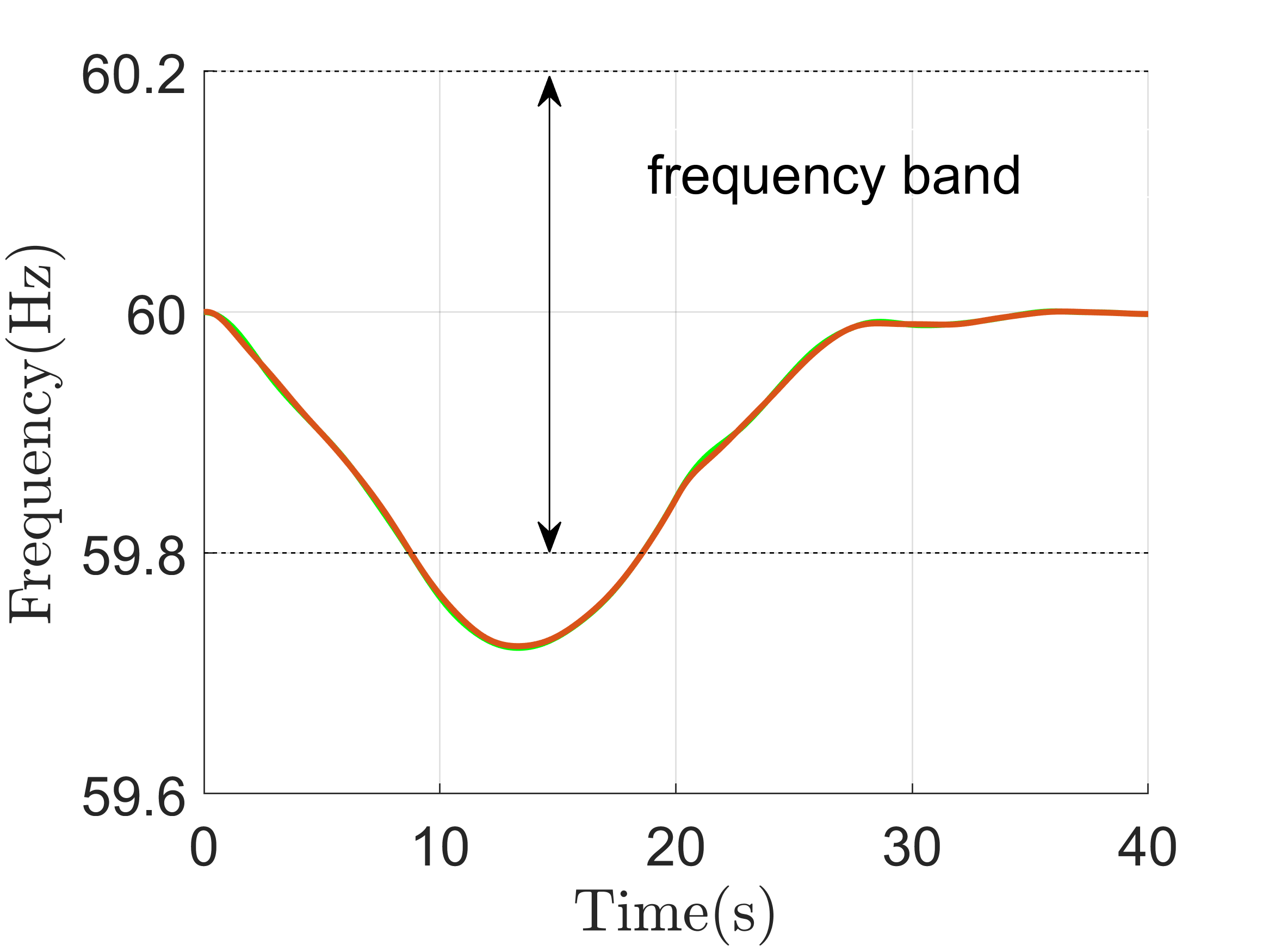
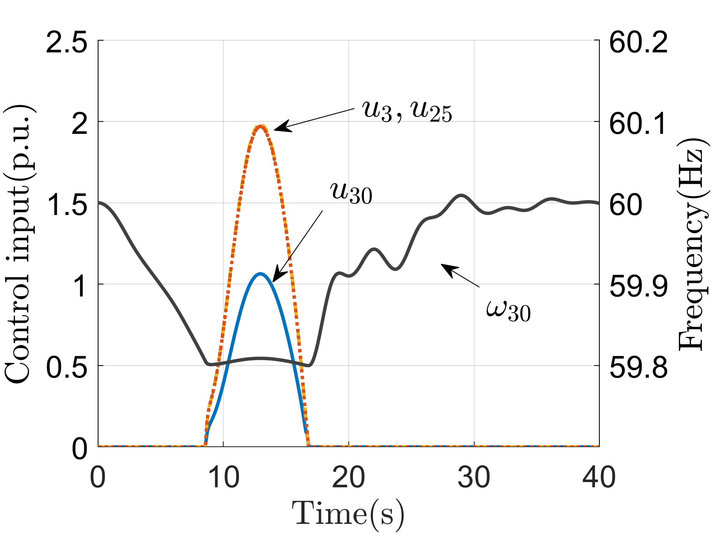
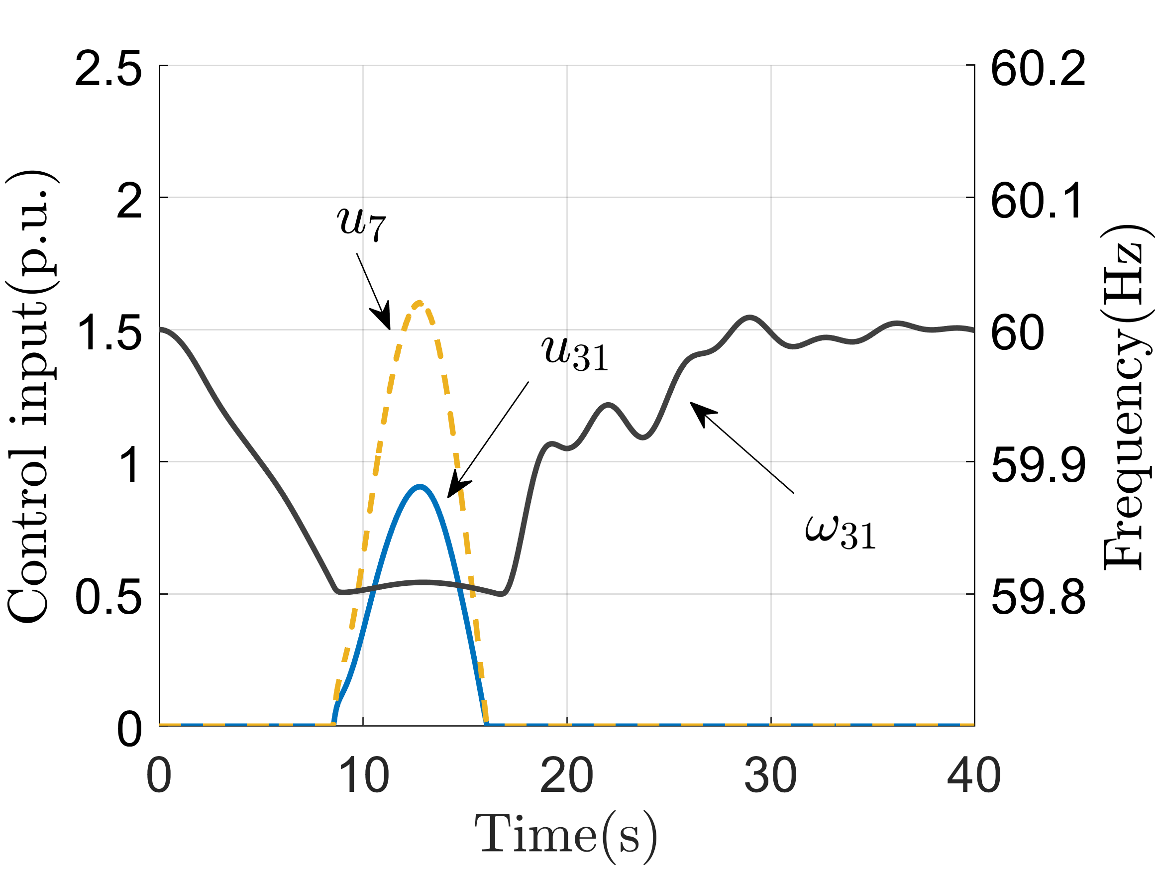
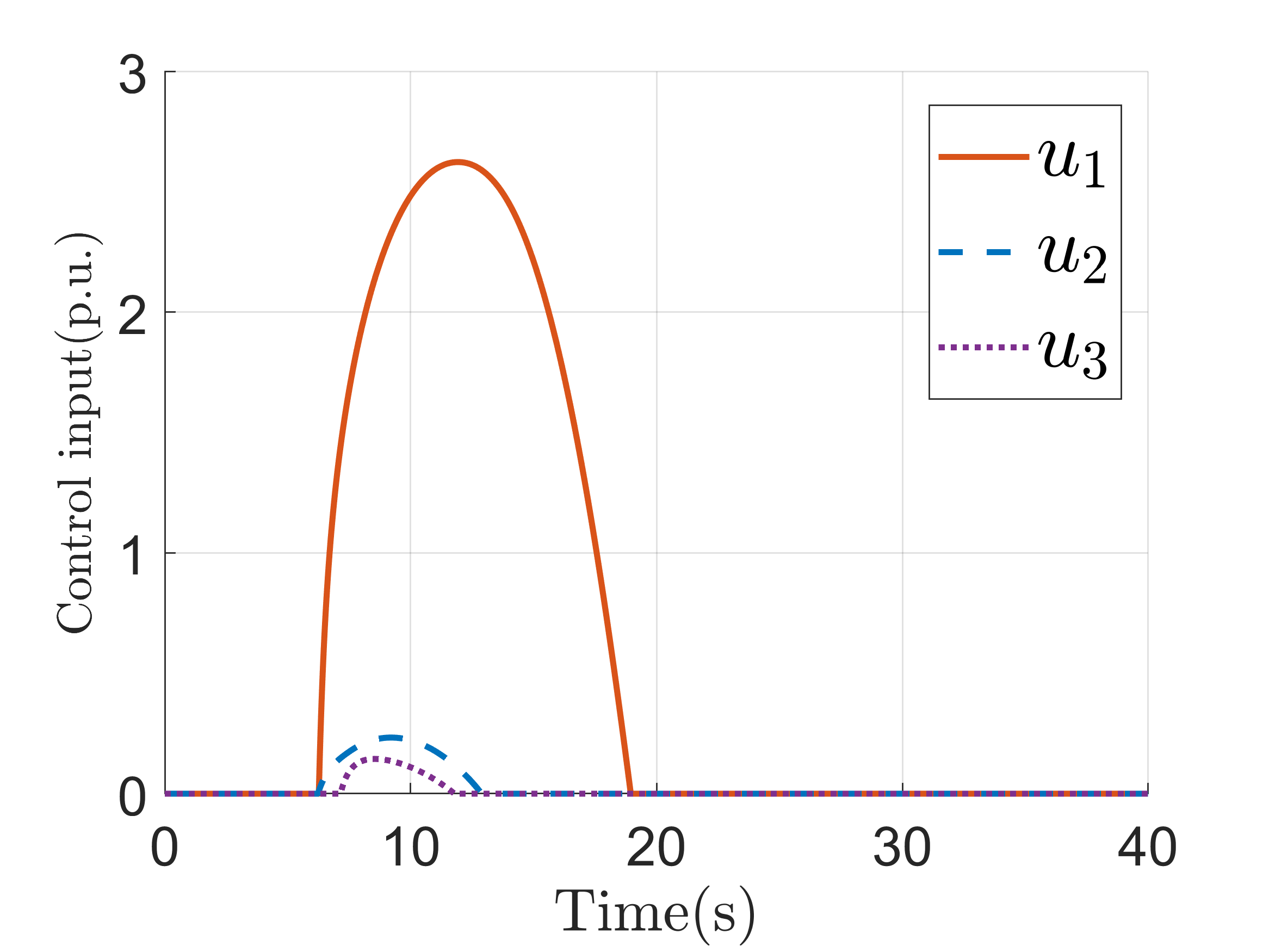
We show that the proposed controller is able to maintain the targeted generator frequencies within the safe region, provided that these frequencies are initially in the safe region. We perturb all non-generator nodes by a sinusoidal power injection whose magnitude is proportional to the corresponding node’s initial power injection. Specifically, for every , let , where for , and for . For , let . Fig. 22(a) shows the open-loop frequency responses of the two generators without the controller. One can see that both trajectories exceed the lower bound around 8s. With the distributed control, Fig. 2(b) and 2(c) show the frequency and control input responses in the left-top region and left-bottom region, resp. Both frequency responses stay within the safe bound all the time and converge to Hz. Also, all control signals vanish to 0 within 20s. In Fig. 2(b), since we assign a higher cost weight on , and the same weight on and , the latter two have almost overlapping trajectory with magnitude higher than the first one. On the other hand, notice that for every , is always 0, while is above the lower frequency threshold denoted by the dashed line. All these observations are in agreement with the result of Proposition 4.4(i)-(iv) (even though the time-varying power injection used here does not satisfy Assumption 2.1).
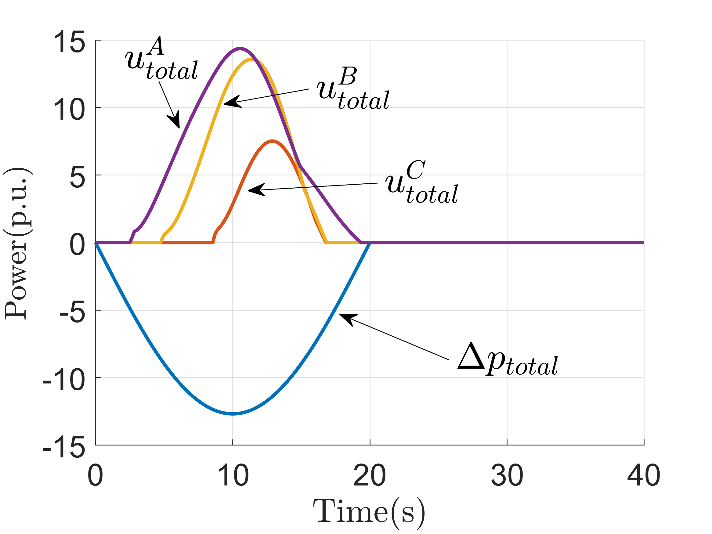
To illustrate the dependence of the control signal on the tightness of transient frequency bounds, we perform a simulation where we replace the frequency bound Hz by Hz and Hz for every . Also, we choose in each case. Figure 3 shows the overall power injection deviation and overall control signal for the above three cases, where for clarity, we add superscripts corresponding to Hz, Hz, and Hz, respectively. Note that the control signal trajectory is larger with tighter frequency bounds, and its shape mimics the trajectory of the power injection deviation to compensate for it. The overall control signal are , , and whereas the power deviation is , suggesting significantly less required control effort as the frequency bound becomes looser.
Next, we simulate the case where generator frequencies are initially outside the safe frequency region to show how the controller brings the frequencies back to the safe region. We apply the same setup used in Fig. 2, but only enable the controller after . The plots in Fig. 4 shows the frequency trajectories and control trajectories of each region. Note that both two frequency trajectories are lower than 59.8Hz at . However, as the controller becomes active after , they come back to the safe region and never leave, in accordance with Proposition 4.4(v).
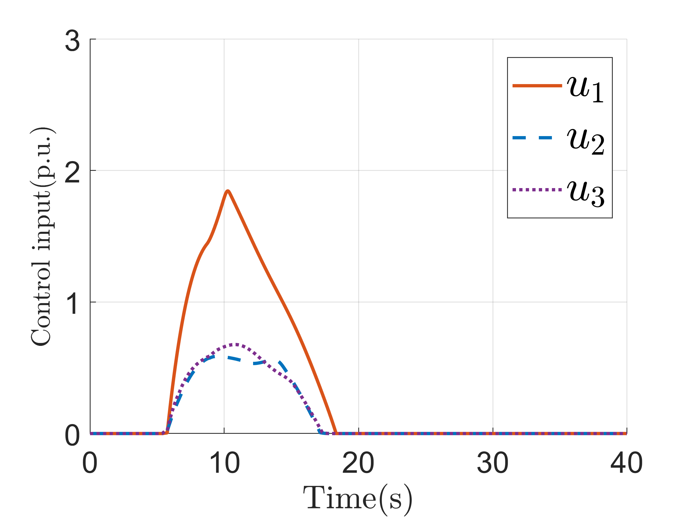
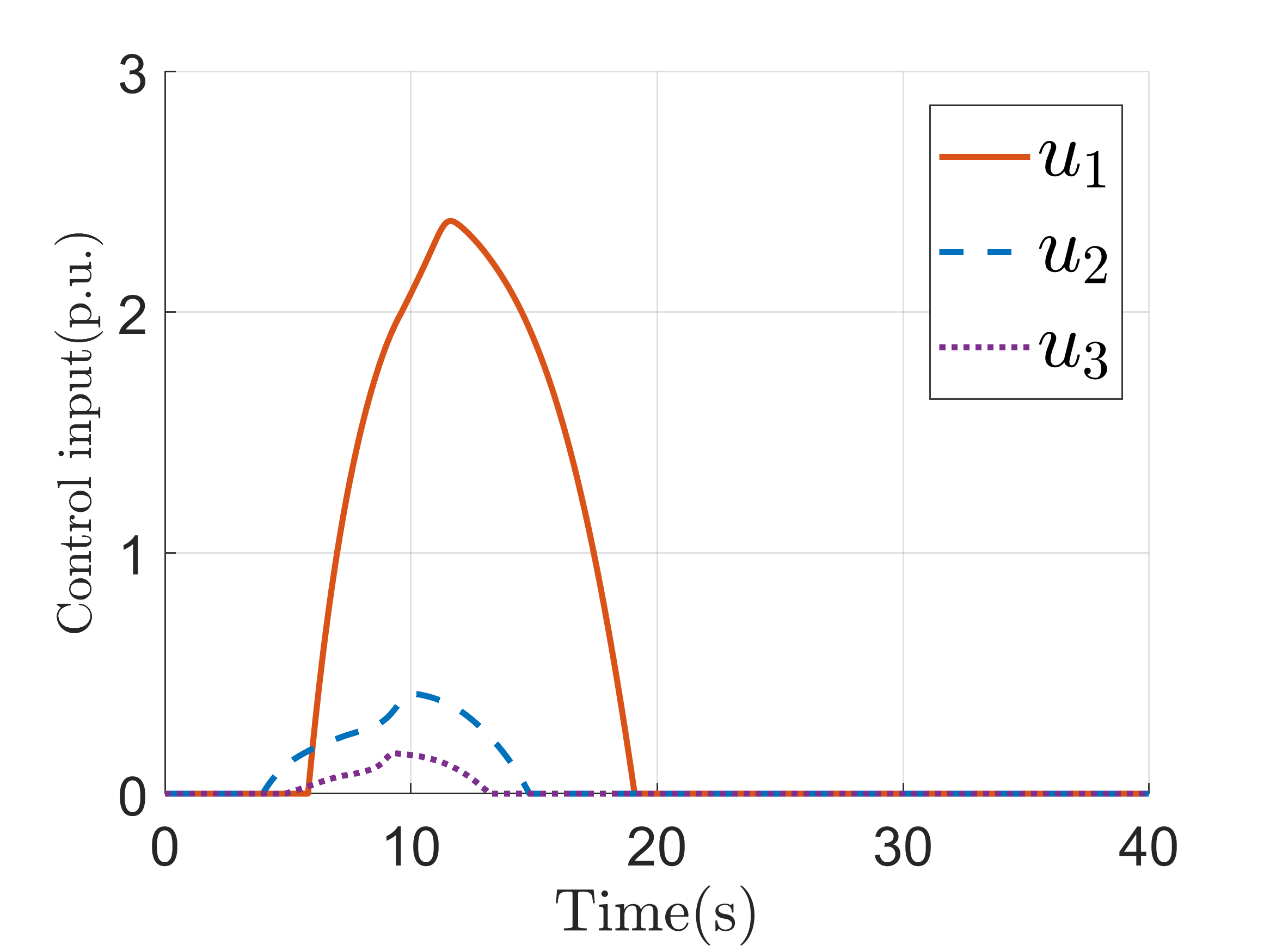
Next, we compare the performance of the centralized controller (20), the distributed controller (26), and the controller we proposed in (Zhang and Cortés, 2019) in the IEEE 9-bus network with the regional partition shown in Fig. 5. Since the control framework in (Zhang and Cortés, 2019) requires that controllers are available only for nodes with transient frequency constraints, for fairness, we let for controllers (20) and (26) (adding nodes with controllers to would further enhance their performance). We employ a similar set-up as in the previous simulation, here with ; for , and for , with the coefficient replaced by in so that the open-loop frequency responses exceed the safe frequency bounds.
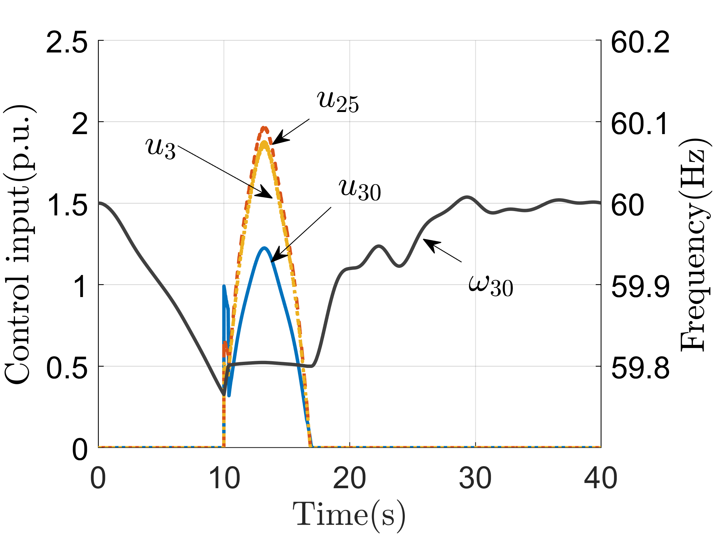
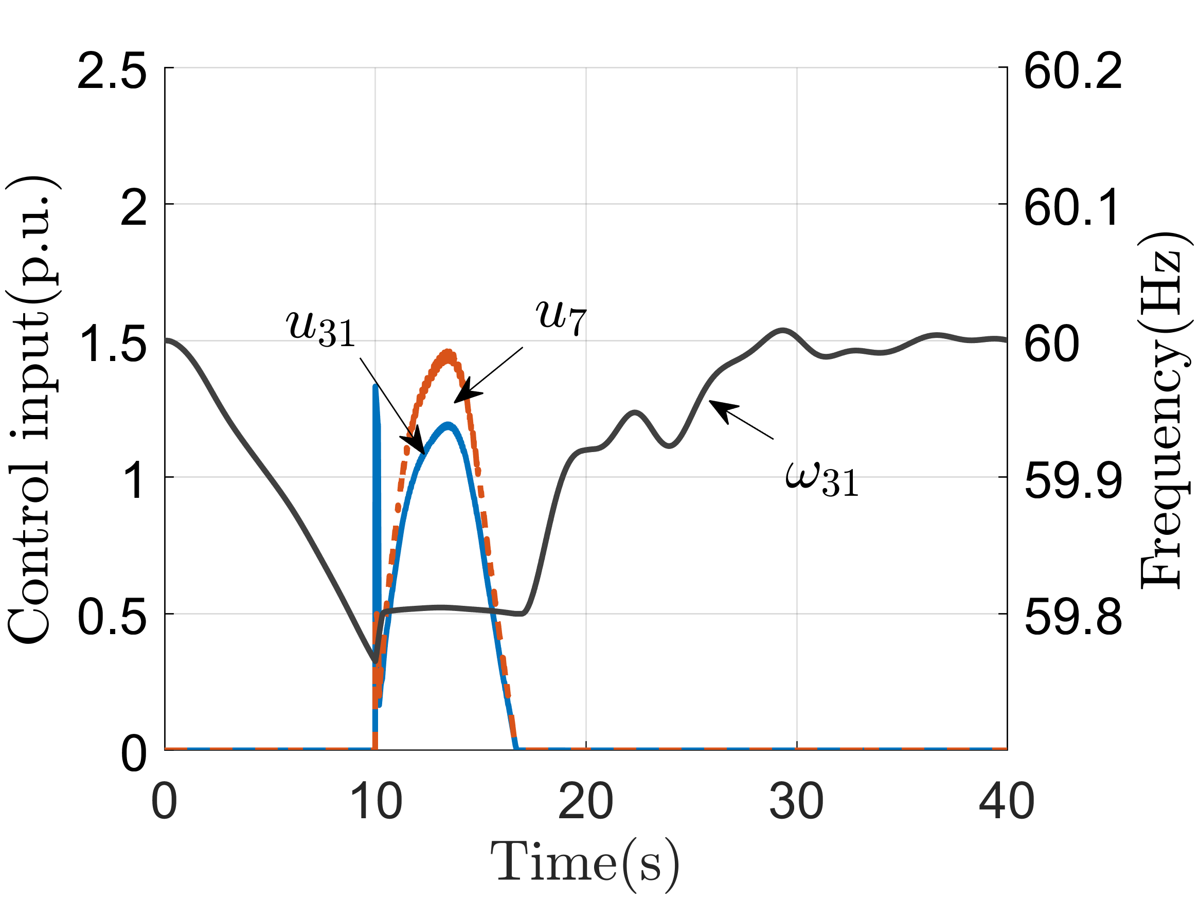

Fig. 6 shows the input trajectories of the generators indexed from 1 to 3 for each of the three controllers. Since all of them achieve frequency invariance and stabilization, we do not show the state trajectories. In terms of the overall control cost, the centralized controller performs the best, due to its capability of accessing the entire network parameters, state, and power injection information, and hence all three generators cooperatively reduce the total cost. This capability is, however, weakened in the distributed controller, as the controller in each region only considers its regional optimality, losing inter-region cooperation. The controller from (Zhang and Cortés, 2019), which is not designed by optimizing control effort, tends to have the largest cost. On the hand, in terms of implementation, the centralized controller requires global network information as well as solving a large-scale optimization problem. In comparison, the distributed controller only accesses network information within its region, and solves a small-scale optimization problem. The controller in (Zhang and Cortés, 2019) can be computed the fastest and only needs information of 1-hop neighbors.
6 Conclusions
We have proposed centralized and distributed model predictive controllers for nonlinear power networks that ensure stability and safe frequency invariance. We have shown that the closed-loop system preserves the equilibrium point and local convergence properties of the open-loop system, and that the control input vanishes in finite time. Future work will quantify the loss in optimality incurred by the convexification of the open-loop optimization problem and the distributed control framework, study the trade-offs between discretization accuracy, reference trajectory qualification, and computational complexity, and analyze the effect of network properties on the performance and characteristics of the proposed controllers.
References
- Alam and Makram [2006] A. Alam and E.B. Makram. Transient stability constrained optimal power flow. In IEEE Power and Energy Society General Meeting, Montreal, Canada, June 2006. Electronic proceedings.
- Borsche et al. [2015] T. S. Borsche, T. Liu, and D. J. Hill. Effects of rotational inertia on power system damping and frequency transients. In IEEE Conf. on Decision and Control, pages 5940–5946, Osaka, Japan, 2015.
- Bullo et al. [2009] F. Bullo, J. Cortés, and S. Martinez. Distributed Control of Robotic Networks. Applied Mathematics Series. Princeton University Press, 2009. ISBN 978-0-691-14195-4.
- Butcher [2008] J. C. Butcher. Numerical Methods for Ordinary Differential Equations. Wiley, New York, 2nd edition, 2008.
- Camponogara et al. [2002] E. Camponogara, D. Jia, B.H. Krogh, and S. Talukdar. Distributed model predictive control. IEEE Control Systems, 22(1):44–52, 2002.
- Cheung et al. [2009] K. W. Cheung, J. Chow, and G. Rogers. Power System Toolbox, v 3.0. Rensselaer Polytechnic Institute and Cherry Tree Scientific Software, 2009.
- Chiang [2011] H. D. Chiang. Direct Methods for Stability Analysis of Electric Power Systems: Theoretical Foundation, BCU Methodologies, and Applications. John Wiley and Sons, 2011.
- Dörfler et al. [2013] F. Dörfler, M. Chertkov, and F. Bullo. Synchronization in complex oscillator networks and smart grids. Proceedings of the National Academy of Sciences, 110(6):2005–2010, 2013.
- Fang et al. [2018] J. Fang, H. Li, Y. Tang, and F. Blaabjerg. On the inertia of future more-electronics power systems. IEEE Journal of Emerging and Selected Topics in Power Electronics, 2018. To appear.
- [10] fmincon function documentation. https://www.mathworks.com/help/optim/ug/fmincon.html#busp5fq-7.
- Jia and Krogh [2002] D. Jia and B. Krogh. Min-max feedback model predictive control for distributed control with communication. In American Control Conference, Anchorage, AK, 2002.
- Khalil [2002] H. K. Khalil. Nonlinear Systems. Prentice Hall, 3 edition, 2002. ISBN 0130673897.
- Kundur [1994] P. Kundur. Power System Stability and Control. McGraw-Hill, 1994. ISBN 007035958X.
- Kundur et al. [2004] P. Kundur, J. Paserba, V. Ajjarapu, G. Andersson, A. Bose, C. Canizares, N. Hatziargyriou, D. Hill, A. Stankovic, C. Taylor, T. V. Cutsem, and V. Vittal. Definition and classification of power system stability. IEEE Transactions on Power Systems, 19(2):1387–1401, 2004.
- Machowski et al. [2008] J. Machowski, J. W. Bialek, and J. R. Bumby. Power System Dynamics: Stability and Control. Wiley, Chichester, England, 2008.
- Mahmud et al. [2014] M. A. Mahmud, H. R. Pota, M. Aldeen, and M. J. Hossain. Partial feedback linearizing excitation controller for multimachine power systems to improve transient stability. IEEE Transactions on Power Systems, 29:561–571, 2014.
- Mayne et al. [2000] D. Q. Mayne, J. B. Rawlings, C. V. Rao, and P. O. M. Scokaert. Constrained model predictive control: Stability and optimality. Automatica, 36:789–814, 2000.
- Milano et al. [2018] F. Milano, F. Dörfler, G. Hug, D. J. Hill, and G. Verbič. Foundations and challenges of low-inertia systems. In Power Systems Computation Conference, Dublin, Ireland, June 2018. Electronic proceedings.
- Monshizadeh and Persis [2017] N. Monshizadeh and C. Persis. Agreeing in networks: Unmatched disturbances, algebraic constraints and optimality. Automatica, 75:63–74, 2017.
- Nazari et al. [2014] M. H. Nazari, Z. Costello, M. J. Feizollahi, S. Grijalva, and M. Egerstedt. Distributed frequency control of prosumer-based electric energy systems. IEEE Transactions on Power Systems, 29:2934–2942, 2014.
- Venkat et al. [2008] A. N. Venkat, Ian A. Hiskens, J. B. Rawlings, and S. J. Wright. Distributed MPC strategies with application to power system automatic generation control. IEEE Transactions on Control Systems Technology, 16(6):1192–1206, 2008.
- Vu et al. [2018] T. L. Vu, H. D. Nguyen, A. Megretski, J. Slotine, and K. Turitsyn. Inverse stability problem and applications to renewables integration. IEEE Control Systems Letters, 2(1):133–138, 2018.
- Zhang and Cortés [2018] Y. Zhang and J. Cortés. Transient frequency control with regional cooperation for power networks. In IEEE Conf. on Decision and Control, pages 2587–2592, Miami Beach, FL, December 2018.
- Zhang and Cortés [2019] Y. Zhang and J. Cortés. Distributed transient frequency control for power networks with stability and performance guarantees. Automatica, 105:274–285, 2019.