∎
2CENN Nanocenter, Jamova 39, 1000 Ljubljana, Slovenia
3Dept. of Physics, Faculty for Mathematics and Physics, Jadranska 19, University of Ljubljana, 1000 Ljubljana, Slovenia
Theoretical Modeling of the Non-equilibrium Amorphous State in 1T-TaS2
Abstract
1T-TaS2 is known for it’s remarkably complex phase diagram and it’s unique long-lived metastable hidden (H) state. Recently, a novel metastable state has been discovered using higher fluences for photoexcitation than in the case of the H state. The state has been dubbed as amorphous (A) due to it’s similarity to glass. Expanding on the work of Brazovskii and Karpov, we show that the A state can be successfully modeled with classical interacting polarons on a two dimensional hexagonal lattice. We have found that the polaron configuration of the A state corresponds to a frustrated screened Coulomb system, where there is no order-disorder phase transition.
Keywords:
Charge density waves Polarons Lattice gas model Monte Carlo simulations1 Introduction
The crystal of 1T-TaS2 (TAS) exhibits a layered structure of S-Ta-S layers, where each of the atomic layers is arranged in a hexagonal lattice. Each Ta atom is surrounded by an octahedral arrangement of S atoms spijkerman1997 . Due to this highly anisotropic character of the crystal we may neglect any kind of three dimensional behavior and only focus on a single layer of TAS.
The interplay of Coulomb interaction fazekas1979electrical , spin-orbit coupling rossnagel2006spin and electron-phonon interaction withers1986examination results in various competing phases of TAS, which emerge as external parameters such as temperature and pressure are varied. When subjected to high pressure TAS becomes superconducting sipos2008 . At ambient pressure and high enough temperatures TAS is a homogeneous metal and upon lowering the temperature a series of charge density wave (CDW) transitions take place thompson1971transitions as follows. At K an incommensurate CDW is formed, where the CDW modulation is incommensurate with underlying atomic lattice. When the temperature is lowered even further, at K, a nearly-commensurate CDW is formed, where a hexagonal structure of domains with a commensurate CDW is separated by domain walls, where the CDW is incommensurate with the atomic lattice. The phase below K has been interpreted as the commensurate CDW phase due to the perfect commensurability of the CDW with the underlying atomic lattice all throughout the crystal. The C phase also exhibits spin liquid like behavior klanjvsek2017 . Fig. 1 shows a schematic of the microscopic picture of the C phase.
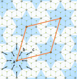
In this paper we adopt the interpretation of the C phase as a system of classical interacting polarons first proposed by Brazovskii brazovskii2015 . Within this interpretation the ratio of the number of polarons and the number of atoms in the system or the polaron concentration is exactly . If polarons repel each other then they will arrange themselves in a hexagonal polaronic lattice, because this is the minimal energy configuration of such a system. The work of Stojchevska et al. stojchevska2014 has shown that the C phase can be photoexcited via an ultra-short laser pulse into a long-lived metastable state. Due to the fact that the excited phase cannot be found on the equilibrium phase diagram of TAS it has been dubbed as the hidden (H) state. Karpov et al. karpov2018 have subsequently shown by performing Monte Carlo simulations of a system of classical repulsive polarons that if the polaron concentration is perturbed slightly from , the H state can be obtained within the scope of this interpretation. The classical Monte Carlo calculations neglect the quantum aspects of polarons and instead focus on the large scale configurational ordering of polarons. Quantum mechanical methods cannot do so due to their computational intensity. Methods used for analyzing the quantum mechanical aspects of polarons in the ground state include exact diagonalization wellein1997polaron , variational exact diagonalization bonvca1999holstein , quantum Monte Carlo de1983numerical , variational methods davydov1979solitons and DMRG jeckelmann1998density . Other methods deal with the polaron dynamics and include Ehrenfest dynamics li2005ab ; donati2016watching , time-dependent density functional theory (TDDFT) polkehn2018quantum , the multiconfiguration time-dependent Hartree method beck2000multiconfiguration , its multilayer formulation wang2003multilayer and the hierachical equations of motion tanimura1989time ; chen2015dynamics . TDDFT has been proven particularly successful in studying phenomena involved in polaron formation and dynamics, such as transient vibration energy redistribution and spectroscopy petrone2016ab and defects in nanomaterials petrone2016quantum ; stein2017cation .
A recent paper by Gerasimenko et al. gerasimenko2018 has reported the discovery of a novel long-lived metastable state, where polarons are arranged in a disordered pattern. It is formed via photoexcitation with an ultrafast laser pulse, which confirms the state’s non-equilibrium nature. It exhibits remarkable stability (at least 10 hours), which excludes any transient nature typically present in excited states. Moreover, even though the polaronic pattern suggests localization of charge, the system exhibits metallic behavior. Therefore the nature of this state is highly non-trivial and physically interesting. The main purpose of this paper is to show that the configurational aspect of the localized charges of this amorphous (A) state can also be understood within the scope of the classical polaron picture and to try to elucidate the reason for the disordered pattern.
2 The Model
The final A state can be modeled in the classical polaron picture of correlated electrons on a hexagonal lattice. TAS is known for the strong presence of the electron-phonon interaction rossnagel2011origin . Therefore, we assume that equation in chapter in alexandrov1995polarons , where small interacting polarons form in a system of electrons and phonons, is applicable. We neglect polaron hopping and spin, as we are only interested in the configurational aspect of the repulsive interaction between polarons. The Hamiltonian has the form
| (1) |
where is the potential energy of interacting polarons, is if the site occupied by a polaron and otherwise, and is the average polaron concentration. is defined as a ratio of the number of polarons in the system, which is fixed throughout the simulation, and the number of lattice sites in the finite lattice used in simulations. The interaction between polarons has two contributions. The attraction due to the overlap of phonon clouds and long range Coulomb repulsion. The first part may be short or long-range depending on the type of phonons involved in polaron formation. If we assume that only polar phonons are responsible for polaron formation, the resulting interaction will be reduced to
| (2) |
where is the static dielectric constant of the material. Both the lattice and electrons contribute to it, however the lattice contribution is indeed dominant. The interaction with acoustic phonons as well as with nonpolar optical phonons leads to the short range attraction of polarons, but here we neglect the short range contribution to the potential. Since the system has finite conductivity the long range Coulomb repulsion is screened. Therefore, we approximate it by the Yukawa potential
| (3) |
where is the screening radius.
3 Monte Carlo Method
Monte Carlo (MC) simulations of simulated annealing were performed using a standard Metropolis algorithm. A proposed successive state in the Markov chain consists of one polaron moving in a random direction and a finite distance away from its current position. Simulations were performed on a hexagonal lattice with the lattice constant and of the size of sites, where periodic boundary conditions were imposed. The number of polarons in the system is constant throughout the simulation procedure. In order to simulate annealing, the system would always start off at a temperature of measured in units of , which corresponds to the high temperature phase of the model for the commensurate (C) state. Afterwards, the system is cooled slowly down to a temperature of with a temperature step of . There were MC steps performed at each temperature step. One of the main reasons for introducing the Yukawa form of the polaron interaction is in the substantial growth of the MC relaxation time with the growth of the range of interaction. The screening length has been chosen as and the interaction has been manually set to at distances greater than . At this value of the interaction range exceeds the radius of one polaron in C state (). Furthermore, it is numerically feasible due to the manageable relaxation times, which follow from it. The code is available for reproducibility at MCcode .
4 Tiling
Tiling of a polaron configuration can serve as a good visual illustration of the effective charge density topography present in the system as well as all the different nearest neighbor distances present between polarons. The way both tilings are achieved is with the help of the so called Voronoi diagram. When a set of coordinates on a plane is given, which are the polaron coordinates, the plane can be partitioned into regions. Each coordinate is assigned a region of points in the plane, which are closer to it than to any other coordinate. This is done for the experimental amorphous state and the theoretical model for it in Fig. 2. Every Voronoi cell has one polaron charge associated with it and if we divide the charge by the cell’s area, we obtain the charge density of the cell. Since the charge of a polaron is fixed (at least in simulations), one can get a clearer perspective on the charge density present in the system just based on the coloring of all the different Voronoi cells. After the Voronoi diagram is complete, one can construct a different set of tiling polygons from the Voronoi diagram’s polygons. Each new polygon has 4 vertices and represents a distance between two neighboring coordinates. The first two vertices are the two neighboring coordinates from which the distance that the polygon represents is calculated. The other two vertices are the two points, which are part of the Voronoi polygons containing the two coordinates and are also the closest to both coordinates. This can be done for any two coordinates, which share two vertices of their Voronoi polygons. Because the distances between polarons in the model are discrete due to the perfect underlying hexagonal lattice, one can specify a color for each tiling polygon based on the distance between the two coordinates it connects. The coloring scheme for the experimental polaron coordinates is extended in the sense that the color spectrum in between any two colors represents the spectrum of all the possible distances between the two discrete distances.
5 Results
Within the scope of the particular lattice gas model used in our simulations, the C phase can be understood as the ground state of a system of polarons, where the polaron concentration is exactly . Experimental measurements of the polaron density in the STM images of the C and amorphous (A) states indicate that the polaron density in A state is about times higher than in C state gerasimenko2018 . Simulations were therefore performed at the corresponding polaron concentration and the result shows similarity with experimental data. Fig. 2 shows the comparison between experiment and theory.
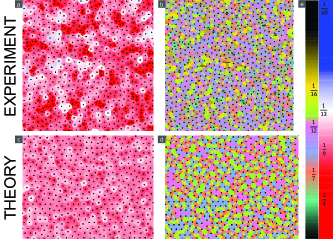
The takeaway from Fig. 2 is the fact that both the theoretical and experimental polaron pattern exhibit disorder. A clearer comparison may be achieved via the polaron pair correlation function . Fig. 3 shows the comparison between the experimental data and theoretical modeling of A state within the scope of .
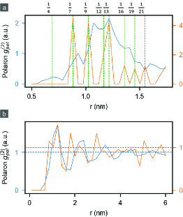
The behavior of the theoretical model’s polaron pair correlation function is qualitatively very similar to the experimental behavior. Consider first Fig. 3a. The green dashed lines mark all the possible lattice constants of polaronic lattices which are commensurate with the hexagonal atomic lattice. From the orange curve it is obvious that the simulation exhibits peaks in these cases. In experiment however, there is a discrepancy in the position of the peaks from the theoretically expected green dashed lines. This can be explained if the underlying atomic lattice has moved slightly in order to accommodate the repulsion between polarons. The qualitative discrepancy in peak intensity is mostly present at the polaron concentration peak, which is much more pronounced than in the experiment. Both of these discrepancies may vanish by incorporating also the movement of the atomic lattice in the model. This is the goal of future studies. In Fig. 3b we can also see a discrepancy between the experimental and simulated peak positions. This is expected already from Fig. 3a, because of the homogeneity of the sample. The behavior at close distances is reflected in long range behavior. Ergo, if there was a discrepancy in the peak positions at close range, it will also be present at long range. The main point of Fig. 3b is to show that despite the peak position discrepancies, both the experimental as well as the theoretical curve tend to the value at large distances. This is a very important feature, as it shows that both exhibit no long range correlations. Within the scope of the theoretical model, the difference between C and A state can be understood by taking a look at a typical annealing process. Fig. 4 shows the energy of the system per polaron dependence on temperature for models of both states measured in units of .
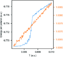
Fig. 5 shows typical configurations of both models at high and low temperatures.
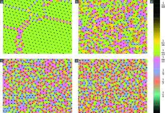
It points out a clear difference in the two low temperature phases of the model for C state (Fig. 5a,b) and A state (Fig. 5c,d). The high temperature configuration in both cases (Fig. 5b,d) is disordered, yet the C state shows a clear strong tendency towards crystallization at low temperatures evident by the dominance of the green color (Fig. 5a). The A state (Fig. 5c) is clearly still disordered even at low temperatures. In the case of the model for C state, there is a clear order-disorder phase transition, which is of the first order. Meanwhile, there is no phase transition present in the case of the model for A state. In the model for A state in Fig. 5c some aggregation of the same types of different nearest neighbor distances can be observed at low simulated temperatures, but no global lattice ever emerges like in the model for C state.
6 Discussion
We have clearly shown that the A state can be modeled successfully within the scope of the classical polaron picture. This result supports the model for the low temperature C state first proposed by Brazovskii brazovskii2015 . This model was also successfully used by Karpov et al. karpov2018 for simulating the H state. Our results imply that the A state’s disordered characteristics are a consequence of commensurability frustration. The polaron hexagonal lattice at this polaron concentration cannot form due to the incommensurability with the underlying atomic lattice. One might argue that phase separation, where multiple commensurate lattices emerge in the system with domain walls in between them, might be energetically more favorable that the disordered phase seen in Fig. 5c. We have shown that this does not happen. Similar behavior has been observed before on a square lattice and it was also attributed to frustration with the underlying lattice lee2002 ; rademaker2013 . Minimization of the overlying hexagonal lattice energy on an underlying hexagonal lattice was done by Pokrovsky et al. pokrovsky1978 . They have shown that multiple minima very close in energy exist at integer polaron concentrations between and as well as between other concentrations. However, it is still not clear whether phase separation would result in further minimization of the energy of the system and whether unscreened interactions would change the system’s behavior. Therefore, the observed glassy behavior may merely be a consequence of the limitations of the Monte Carlo algorithm, or perhaps the glassy behavior is an actual thermodynamic property of the system at this polaron concentration.
7 Conclusion
In this paper the newly discovered meta-stable amorphous state in 1T-TaS2 has been successfully modeled within the scope of a classical gas of polarons. The disordered structure has been found to be a consequence of frustration in the system. The hexagonal lattice of the polaron gas which seeks to emerge due to the repulsive interaction between them in not commensurate with the hexagonal underlying atomic lattice. According to our Monte Carlo simulations the result of this frustration is a remarkable stability of a disordered polaronic pattern, where there is no evidence of a first order crystallization phase transition. Our finding represent a new and important step in understanding photoexcitation in the complex system of 1T-TaS2. The external laser pulse causes the system to form a greater number of polarons than in the thermodynamically stable commensurate state. Afterwards, polarons order in compliance with the screened interaction between them and the atomic lattice underneath into a stable disordered pattern.
Acknowledgements.
We wish to thank Tomaz Mertelj for the useful discussions. The work was supported by ERC-2012-ADG_20120216 “Trajectory” and the Slovenian Research Agency (program P1-0040 and young researcher P0-8333).References
- (1) A. Spijkerman, J.L. de Boer, A. Meetsma, G.A. Wiegers, S. van Smaalen, X-ray crystal-structure refinement of the nearly commensurate phase of 1 t- tas 2 in (3+ 2)-dimensional superspace, Physical review B 56(21), 13757 (1997)
- (2) P. Fazekas, E. Tosatti, Electrical, structural and magnetic properties of pure and doped 1t-tas2, Philosophical Magazine B 39(3), 229 (1979)
- (3) K. Rossnagel, N. Smith, Spin-orbit coupling in the band structure of reconstructed 1 t- tas 2, Physical Review B 73(7), 073106 (2006)
- (4) R. Withers, J. Wilson, An examination of the formation and characteristics of charge-density waves in inorganic materials with special reference to the two-and one-dimensional transition-metal chalcogenides, Journal of Physics C: Solid State Physics 19(25), 4809 (1986)
- (5) B. Sipos, A.F. Kusmartseva, A. Akrap, H. Berger, L. Forró, E. Tutiš, From mott state to superconductivity in 1T-TaS2, Nature materials 7(12), 960 (2008)
- (6) A. Thompson, R. Gamble, J. Revelli, Transitions between semiconducting and metallic phases in 1-t tas2, Solid State Communications 9(13), 981 (1971)
- (7) M. Klanjšek, A. Zorko, J. Mravlje, Z. Jagličić, P.K. Biswas, P. Prelovšek, D. Mihailovic, D. Arčon, et al., A high-temperature quantum spin liquid with polaron spins, Nature Physics (2017)
- (8) S. Brazovskii, Modeling of evolution of a complex electronic system to an ordered hidden state: Application to optical quench in 1T-TaS2, Journal of Superconductivity and Novel Magnetism 28(4), 1349 (2015)
- (9) L. Stojchevska, I. Vaskivskyi, T. Mertelj, P. Kusar, D. Svetin, S. Brazovskii, D. Mihailovic, Ultrafast switching to a stable hidden quantum state in an electronic crystal, Science 344(6180), 177 (2014)
- (10) P. Karpov, S. Brazovskii, Modeling of networks and globules of charged domain walls observed in pump and pulse induced states, Scientific reports 8(1), 4043 (2018)
- (11) G. Wellein, H. Fehske, Polaron band formation in the holstein model, Physical Review B 56(8), 4513 (1997)
- (12) J. Bonča, S. Trugman, I. Batistić, Holstein polaron, Physical Review B 60(3), 1633 (1999)
- (13) H. De Raedt, A. Lagendijk, Numerical calculation of path integrals: the small-polaron model, Physical Review B 27(10), 6097 (1983)
- (14) A.S. Davydov, Solitons in molecular systems, Physica Scripta 20(3-4), 387 (1979)
- (15) E. Jeckelmann, S.R. White, Density-matrix renormalization-group study of the polaron problem in the holstein model, Physical Review B 57(11), 6376 (1998)
- (16) X. Li, J.C. Tully, H.B. Schlegel, M.J. Frisch, Ab initio ehrenfest dynamics, The Journal of chemical physics 123(8), 084106 (2005)
- (17) G. Donati, D.B. Lingerfelt, A. Petrone, N. Rega, X. Li, “watching” polaron pair formation from first-principles electron–nuclear dynamics, The Journal of Physical Chemistry A 120(37), 7255 (2016)
- (18) M. Polkehn, P. Eisenbrandt, H. Tamura, I. Burghardt, Quantum dynamical studies of ultrafast charge separation in nanostructured organic polymer materials: Effects of vibronic interactions and molecular packing, International Journal of Quantum Chemistry 118(1), e25502 (2018)
- (19) M.H. Beck, A. Jäckle, G. Worth, H.D. Meyer, The multiconfiguration time-dependent hartree (mctdh) method: a highly efficient algorithm for propagating wavepackets, Physics reports 324(1), 1 (2000)
- (20) H. Wang, M. Thoss, Multilayer formulation of the multiconfiguration time-dependent hartree theory, The Journal of chemical physics 119(3), 1289 (2003)
- (21) Y. Tanimura, R. Kubo, Time evolution of a quantum system in contact with a nearly gaussian-markoffian noise bath, Journal of the Physical Society of Japan 58(1), 101 (1989)
- (22) L. Chen, Y. Zhao, Y. Tanimura, Dynamics of a one-dimensional holstein polaron with the hierarchical equations of motion approach, The journal of physical chemistry letters 6(15), 3110 (2015)
- (23) A. Petrone, D.B. Lingerfelt, D.B. Williams-Young, X. Li, Ab initio transient vibrational spectral analysis, The journal of physical chemistry letters 7(22), 4501 (2016)
- (24) A. Petrone, J.J. Goings, X. Li, Quantum confinement effects on optical transitions in nanodiamonds containing nitrogen vacancies, Physical Review B 94(16), 165402 (2016)
- (25) J.L. Stein, M.I. Steimle, M.W. Terban, A. Petrone, S.J. Billinge, X. Li, B.M. Cossairt, Cation exchange induced transformation of inp magic-sized clusters, Chemistry of Materials 29(18), 7984 (2017)
- (26) Y. Gerasimenko, I. Vaskivskyi, J. Ravnik, J. Vodeb, V.V. Kabanov, D. Mihailovic, Ultrafast jamming of electrons into an amorphous entangled state, arXiv preprint arXiv:1803.00255 (2018)
- (27) K. Rossnagel, On the origin of charge-density waves in select layered transition-metal dichalcogenides, Journal of Physics: Condensed Matter 23(21), 213001 (2011)
- (28) A.S. Alexandrov, N.F. Mott, Polarons & bipolarons (World Scientific, 1995)
-
(29)
Monte carlo code.
https://github.com/JakaVodeb
Physics/MonteCarloSimulatedAnnealing. Accessed: 2018-09-20 - (30) S.J. Lee, B. Kim, J. Lee, Infinite ground state degeneracy and glassy dynamics in the frustrated xy model and lattice coulomb gas with f= 16, Physica A: Statistical Mechanics and its Applications 315(1), 314 (2002)
- (31) L. Rademaker, Y. Pramudya, J. Zaanen, V. Dobrosavljević, Influence of long-range interactions on charge ordering phenomena on a square lattice, Physical Review E 88(3), 032121 (2013)
- (32) V. Pokrovsky, G. Uimin, On the properties of monolayers of adsorbed atoms, Journal of Physics C: Solid State Physics 11(16), 3535 (1978)