Swansea University
Swansea, Wales
SA1 8EN
j.h.stovold@swansea.ac.uk
RDCSim: a GPU-Accelerated, Interactive Simulator for Reaction–Diffusion Chemistry
Abstract
This paper presents RDCSim, an interactive simulator for reaction–diffusion chemistry (RDC) research, being developed as part of an ongoing project studying how humans interact with unconventional computing systems.
While much research into the computational properties of RDC makes use of simulations, the development of multiple RDC simulations across different research groups can lead to results that are harder to reproduce. By automating the storage of parameter values alongside simulation results, RDCSim aims to make reproducing RDC results painless.
This paper presents the functionality of RDCSim, and verifies the behaviour of the underlying chemical simulation using two seminal examples from the RDC literature: logical AND gates and chemical diodes.
1 Introduction
Reaction–diffusion chemistry (RDC) is an unconventional computing paradigm that exploits the interaction of emergent chemical waves for computation [1, 2, 3, 4, 5, 7, 9, 10, 11, 20, 21, 22, 23]. This paper presents RDCSim, an interactive simulator for RDC being developed as part of an ongoing project looking at how humans interact with unconventional computing systems.
Due to the difficulties associated with producing oscillatory chemical reactions [27, 28] in a wet lab environment, a large number of papers that present results related to RDC make use of simulations for their experiments [2, 3, 7, 20, 21, 22, 23]. While there is consensus on the accuracy of the mathematical models compared with the underlying chemical reactions, the specific implementations of the models can vary between simulations. This increases the risk that results are not consistently reproducible. This impact of this risk can be reduced by developing a single, open-source RDC simulator that provides complete transparency around parameter values and the underlying chemical model used for each simulated result.
RDCSim aims to bring together a single implementation of the most commonly-used RDC models and provide functionality to automatically store parameter values alongside results in a consistent, structured format. Furthermore, implementing RDCSim on a tablet opens the possibility of studying the interaction of humans with unconventional computing substrates.
Finally, RDCSim can be used in research for rapidly designing RDC circuits, and in outreach activities to introduce the ideas behind unconventional computing to a wider audience.
This paper is organised as follows: section 2 provides the preliminary background about RDC, and details the chemical model used by RDCSim; section 3 describes the functionality of the RDCSim app; section 4 demonstrates the basic correctness of the implemented system by reproducing key results from the literature; finally, section 5 discusses future work and concludes the paper.
2 Reaction–Diffusion Chemistry
Reaction–diffusion chemistry (RDC) is a chemical reaction that changes state such that emergent wavefronts of reagent diffuse across the reactor. The most widely-used models are based on the Belousov–Zhabotinsky (BZ) reaction [6, 27], which may display single waves of reaction or an oscillation between two observable states, depending on the setup used.
The use of a diffusive chemical reaction as a computational medium has been studied in detail, with many image processing operations implemented in the substrate [12, 13, 14]. The intrinsically parallel nature of RDC makes it an ideal candidate for such operations. Other researchers have focussed on the computational power of RDC, looking at maze solving [18], Voronoi diagram construction [26]; chemical diodes [5]; and involutes [15]. Recently, much attention has been given to the similarities between neuronal behaviour and RDC, including spiking neural networks [21], associative memory [22, 23], and dynamic neural field theory [16, 19].
In RDCSim, the BZ reaction is simulated using the two-variable Oregonator model [8]:
| (1) |
The default parameter values for the model are given in table 1. The parameters (, , , , ) are described in detail in [10], but (briefly): is a scaling factor, is the stoichimetric coefficient (a conservation of mass parameter), is a propagation scaling factor, represents the excitability of the substrate, and is the diffusion coefficient for the solution.
| Parameter | Value |
|---|---|
| 0.0243 | |
| 1.4 | |
| 0.054 | |
| 0.0975 | |
| 0.002 | |
| 0.45 | |
| 0.001 | |
| 0.25 |
The model in eqn. 1 is numerically integrated using an explicit forward Euler integration, with timestep and five-node discrete Laplace operator with grid spacing . Catalytic stimulation is achieved by setting the excitatory concentration () of stimulated pixels to 1.0.
The implemented model is accelerated using a GPU, making the simulation sufficiently responsive for user interaction. Due to this acceleration, the user is able to vary the observable speed of the simulation according to preference or experimental requirement. This is achieved by varying how often the reaction is rendered to screen.
3 Functionality of the Simulator
RDCSim is built as an iPad app, making use of the built in GPU for accelerating the chemical model. All testing has been performed on the 2017 10.5in iPad Pro running iOS 12.0. This tablet runs an Apple A10X ARM CPU, with 6 cores running at 2.38GHz, 4GB RAM, and a 12-core GPU. By building RDCSim as an app, the touchscreen capabilities of a tablet make designing and running RDC experiments substantially easier. The user is able to stimulate the reaction with a catalyst using their finger or stylus, and are able to draw circuits in the same way.
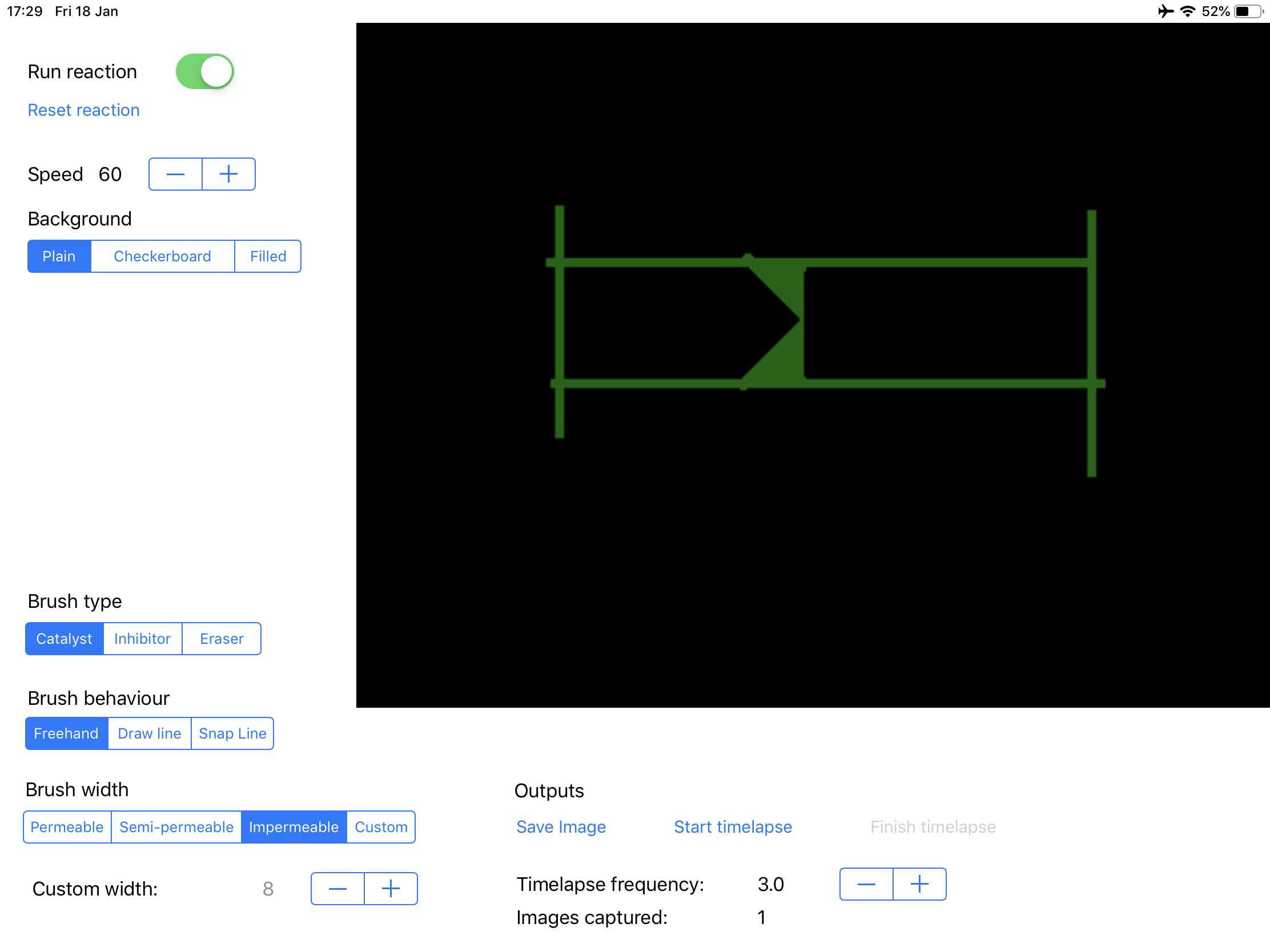
The RDCSim app, the interface for which is shown in fig. 1, has a range of functionality implemented with much more planned for development in the near future. The order with which this future functionality is implemented will depend on the requirements when running human experiments and on specific requests from other researchers using the app.
At present, the system allows for freehand and line drawing of inhibitive substrate and catalytic stimulation. Furthermore, to aid in the development of logical circuits, a ‘snap line’ option has been introduced that draws a line restricted to multiples of 15-degree angles only.
The width of the lines drawn can be customised by the user, with presets implemented that permit different degrees of wave permeability. ‘Permeable’ lines only slow the propagating waves; ‘semi-permeable’ lines allow waves to pass that approach perpendicular to the barrier, but not parallel, making them ideal for logical AND gates (see sect. 4.1); ‘impermeable’ line stop all waves. In the presets for RDCSim, these are defined as 2, 3, and 8 pixels wide for permeable, semi-permeable, and impermeable lines, respectively.
Furthermore, presets for the background have been implemented so that the user can choose to work by removing substrate from a filled background or by adding it to an empty background. There are plans to implement saving and loading of user-defined backgrounds in the near future. Fig. 1 shows the user interface of the system, with an empty background (black) and a diode circuit being tested.
As described in section 2 the chemical model currently implemented in RDCSim is the two-variable Oregonator model [8], based on the well-known Belousov–Zhabotinsky (BZ) reaction [27, 28]. At present, the variables for this model are fixed but work is ongoing to make these available to change by the user, along with providing presets for different observed behaviours (such as sub-excitable wave fragments [4]).
Finally, one of the key objectives for this project is to increase the reproducibility of results in RDC research, so the next major release of RDCSim will include database integration. This will provide a way to consistently save results and parameter values alongside one another. Moreover, by using a structured format for parameters and results, these can be re-loaded into RDCSim for verification at a later date.
3.1 Outputs from the Simulator
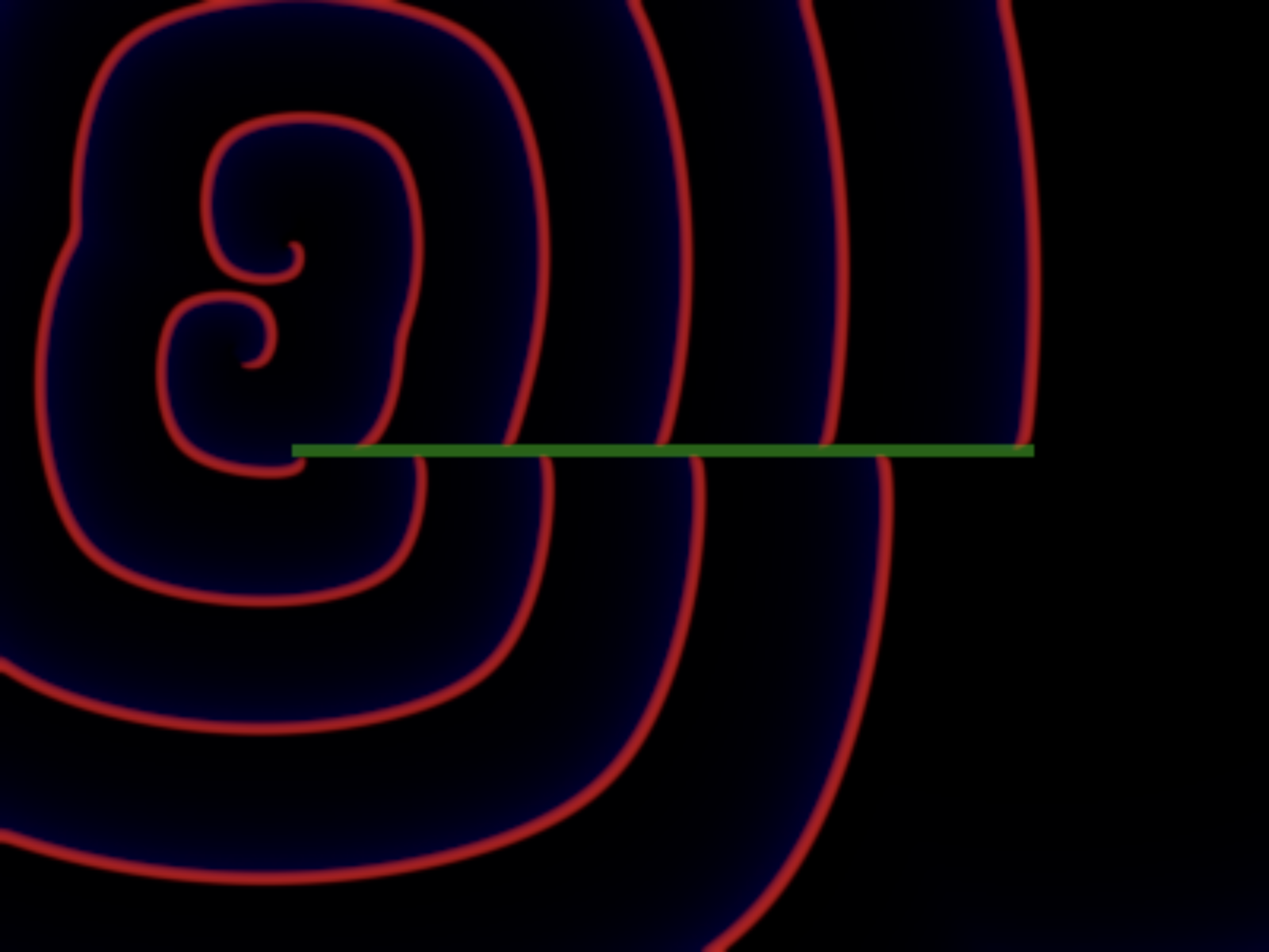
The simulated reaction is rendered to screen using the following colour-mapping:
-
Red pixels: concentration of
-
Green pixels: inhibitive substrate
-
Blue pixels: concentration of
Fig. 2 shows an image rendered by the app, displaying alternating waves above and below the inhibitor, produced by the dual spiral patterns in the top-left.
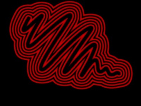
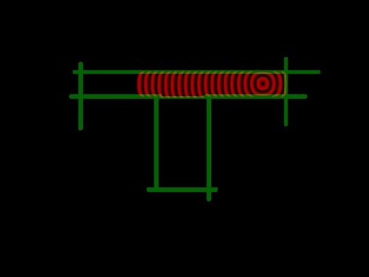
There are currently two ways to output results from the simulator. The first saves a snapshot of the current state of the reaction to an image on the tablet. The second records a timelapse of the reaction at a rate set by the user. This timelapse can then be saved as an image to the tablet. In order to improve the clarity of timelapse images, only the concentration of is recorded over time, and overlaid on top of the static inhibitive substrate. An example snapshot and timelapse image are provided in figs. 3a and 3b.

4 Basic Behaviour Verification
To demonstrate that the system is working correctly, this section reproduces two seminal RDC results from the literature: the logical AND gate [9] and chemical diode [5]. All circuits and catalytic stimulation used in this section have been drawn by hand using the tablet interface, and results are presented using the standard outputs from the simulator.
4.1 Logical AND Gate
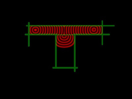
Due to the lack of a clock signal in RDC, a logical AND gate is equivalent to a coincidence detector [9]. By arranging two active regions separated by a passive region (as shown in fig. 4), the wave can only propagate across the passive region if two waves collide opposite the output region.

Fig. 5a shows a timelapse image of a single input entering the implemented gate, demonstrating that it is not able to propagate to the bottom of the circuit, where the output is measured. When both inputs are present, however, as in fig. 5b, the interaction between the two waves is sufficient to stimulate the output region and form an output wave. As such, the conjunctive logic is implemented and successfully demonstrated.
4.2 Chemical Diode
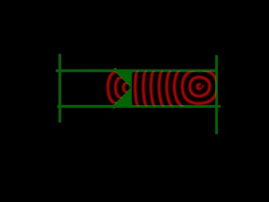
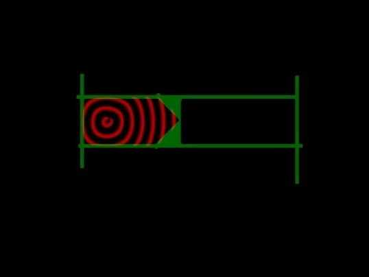
The chemical diode [5] is an essential component for any medium- or large-sized RDC circuit. It prevents waves from propagating in an unintended direction through the circuit. The basic chemical diode is a very simple design (see fig. 6), consisting of a gap in active substrate with a pointed interface on the cathode side of the diode and a flat interface on the anode side of the diode.111assuming the chemical waves follow conventional current, although arguably the emergent waves in an RDC system are more similar to voltage waves, which would reverse the description of anode/cathode arrangement presented here, but not the behaviour

This design for a diode is implemented in RDCSim and allows chemical waves to propagate from the anode to the cathode, but not from the cathode to the anode—as shown in figs. 7a and 7b.
5 Future Work
While the simulation is currently sufficient to run simple experiments, there are a substantial number of improvements planned for the near future. The first improvement is already under development, to allow users to alter the chemical model parameters and to integrate the simulation with a database to store the parameter values alongside simulation outputs. This will help to improve consistent reproducibility of results, one of the primary aims for developing RDCSim.
Furthermore, the ability for users to save and load presets, and to save and load circuits / backgrounds is a high priority, again helping to improve reproducibility across experiments, but also to improve the speed with which researchers can develop RDC solutions.
Finally, the long-term plans for RDCSim include development of multiple chemical models, vesicle models, and the ability to record inputs in real-time. These will help to expand the user base for the simulator, but are not essential for current research plans.
The primary application for this RDCSim is for the study of human–RDC interaction. By studying how lay humans naturally interact with a chemical substrate, novel forms of human–computer interaction could be formed which can help inform current practice. The use of tangible chemical interfaces are already being investigated [17, 25, 24], and combining the computational power of diffusive computing with the interfaces already under development offers a route towards radically-different computing systems in future.
6 Summary
This paper has presented the ongoing development work of RDCSim, a GPU-accelerated, interactive simulator for reaction–diffusion chemistry research. The simulator is verified using two seminal examples from the RDC literature: logical AND gates and chemical diodes.
There are two main aims for RDCSim. The first is to develop a simulator that enables effortlessly-reproducible RDC research. The second is to use the app to study how humans interact with unconventional computing systems. The work in this paper represents the first step towards these aims, providing a system that can be used for basic human interaction studies.
Finally, the author hopes that other RDC researchers will make use of, and contribute to, the
development of the simulator222the code for RDCSim is open-source and available at
https://github.com/jstovold/RDCSimulator, and that through various outreach events
it can be used to encourage new interest in unconventional computing methods.
References
- [1] Adamatzky, A., De Lacy Costello, B., Asai, T.: Reaction–Diffusion Computers. Elsevier Science (2005)
- [2] Adamatzky, A., Holley, J., Bull, L., de Lacy Costello, B.: On computing in fine-grained compartmentalised Belousov–Zhabotinsky medium. Chaos Solitons & Fractals 44, 779–790 (Oct 2011)
- [3] Adamatzky, A.: Collision-based computing in Belousov–Zhabotinsky medium. Chaos, Solitons & Fractals 21(5), 1259–1264 (2004)
- [4] Adamatzky, A., De Lacy Costello, B.: Binary collisions between wave-fragments in a sub-excitable Belousov–Zhabotinsky medium. Chaos, Solitons & Fractals 34(2), 307–315 (2007)
- [5] Agladze, K., Aliev, R.R., Yamaguchi, T., Yoshikawa, K.: Chemical diode. J. Phys. Chem 100, 13895–13897 (1996)
- [6] Belousov, B.P.: A periodic reaction and its mechanism. Med. Publ., Moscow (1959)
- [7] Costello, B.D.L., Adamatzky, A., Jahan, I., Zhang, L.: Towards constructing one-bit binary adder in excitable chemical medium. Chemical Physics 381(1), 88–99 (2011)
- [8] Field, R.J., Janz, R.D., Vanecek, D.J.: Composite double oscillation in a modified version of the Oregonator model of the Belousov–Zhabotinsky reaction. The Journal of Chemical Physics 73(7), 3132–3138 (1980)
- [9] Gorecki, J., Yoshikawa, K., Igarashi, Y.: On chemical reactors that can count. The Journal of Physical Chemistry A 107(10), 1664–1669 (2003)
- [10] Holley, J., Adamatzky, A., Bull, L., De Lacy Costello, B., Jahan, I.: Computational modalities of Belousov–Zhabotinsky encapsulated vesicles. ArXiv e-prints (Sep 2010)
- [11] Holley, J., Jahan, I., De Lacy Costello, B., Bull, L., Adamatzky, A.: Logical and arithmetic circuits in Belousov–Zhabotinsky encapsulated disks. Phys. Rev. E 84, 056110 (Nov 2011)
- [12] Kuhnert, L.: A new optical photochemical memory device in a light-sensitive chemical active medium. Nature 319(6052), 393–394 (Jan 1986)
- [13] Kuhnert, L.: Photochemische manipulation von chemischen wellen (in German). Naturwissenschaften 73, 96–97 (1986)
- [14] Kuhnert, L., Agladze, K.I., Krinsky, V.I.: Image processing using light-sensitive chemical waves. Nature 337(6204), 244–247 (Jan 1989)
- [15] Lázár, A., Noszticzius, Z., Farkas, H., Försterling, H.D.: Involutes: the geometry of chemical waves rotating in annular membranes. Chaos 5(2), 443–447 (1995)
- [16] Rambidi, N., Maximychev, A., Usatov, A.: Molecular neural network devices based on non-linear dynamic media. Biosystems 33(2), 125–137 (1994)
- [17] Sahoo, D.R., Neate, T., Tokuda, Y., Pearson, J., Robinson, S., Subramanian, S., Jones, M.: Tangible drops: A visio-tactile display using actuated liquid-metal droplets. In: Proceedings of the 2018 CHI Conference on Human Factors in Computing Systems. pp. 177:1–177:14. CHI ’18, ACM (2018)
- [18] Steinbock, O., Tóth, Á., Showalter, K.: Navigating complex labyrinths: Optimal paths from chemical waves. Science 267(5199), 868–871 (1995)
- [19] Stovold, J.: Extending the Computational Application of Reaction–Diffusion Chemistry by Modelling Artificial Neural Networks. Master’s thesis, University of York (2012)
- [20] Stovold, J., O’Keefe, S.: How appropriate are logic gates in reaction–diffusion chemistry? In: Bandur, V. (ed.) Proc. 5th York Doctoral Symposium on Computer Science. vol. 5, pp. 17–26. University of York (2012)
- [21] Stovold, J., O’Keefe, S.: Simulating neurons in reaction-diffusion chemistry. In: Lones, M.A., Smith, S.L., Teichmann, S., Naef, F., Walker, J.A., Trefzer, M.A. (eds.) Proc. IPCAT 2012, LNCS 7223. pp. 143–149 (2012)
- [22] Stovold, J., O’Keefe, S.: Associative memory in reaction–diffusion chemistry. In: Adamatzky, A. (ed.) Advances in Unconventional Computing: Volume 2: Prototypes, Models and Algorithms, pp. 141–166. Springer International Publishing (2017)
- [23] Stovold, J., O’Keefe, S.: Reaction–diffusion chemistry implementation of associative memory neural network. International Journal of Parallel, Emergent and Distributed Systems 32(1), 74–94 (2017)
- [24] Tokuda, Y., Moya, J.L.B., Memoli, G., Neate, T., Sahoo, D.R., Robinson, S., Pearson, J., Jones, M., Subramanian, S.: Programmable liquid matter: 2d shape deformation of highly conductive liquid metals in a dynamic electric field. In: Proceedings of the 2017 ACM International Conference on Interactive Surfaces and Spaces. pp. 142–150. ISS ’17, ACM (2017)
- [25] Tokuda, Y., Moya, J.L.B., Memoli, G., Neate, T., Sahoo, D.R., Robinson, S., Pearson, J., Jones, M., Subramanian, S.: Programmable liquid matter: 2d shape drawing of liquid metals by dynamic electric field. In: Proceedings of the 2017 ACM International Conference on Interactive Surfaces and Spaces. pp. 454–457. ISS ’17, ACM (2017)
- [26] Tolmachiev, D., Adamatzky, A.: Chemical processor for computation of Voronoi diagram. Advanced Materials for Optics and Electronics 6(4), 191–196 (1996)
- [27] Zhabotinsky, A.M.: Periodic course of the oxidation of malonic acid in a solution (studies on the kinetics of Belousov’s reaction). Biofizika 9 (1964)
- [28] Zhabotinsky, A., Zaikin, A.: Autowave processes in a distributed chemical system. Journal of Theoretical Biology 40(1), 45–61 (1973)