Large Q factor with very small Whispering Gallery Modes resonators
Abstract
Efficient micro-resonators simultaneously require a large quality factor and a small volume . However, the former is ultimately limited by bending losses, the unavoidable radiation of energy of a wave upon changing direction of propagation. Such bending losses increase exponentially as decreases and eventually result in a drop of . Therefore, circular cavities are generally designed with radii that are much larger than the optical wavelength. The same leakage of energy by radiation limits the sharpness of bends in photonic integrated circuits. In this article, we present a way to reduce bending losses in circular micro-resonators. The proposed scheme consists of one or more external dielectric rings that are concentric with the cavity. These rings alter the field outside the cavity where radial oscillations set in, and thus control the far field radiation. As a result, the factor can be increased by several orders of magnitude while keeping a small cavity volume.
I Introduction
Whispering gallery mode (WGM) resonators occupy a place of choice in experiments and devices where enhanced light-matter interaction is required. The reason of their interest in both fundamental and applied research is that WGM can have a very long lifetime, measured by the quality factor , while occupying a small volume Matsko and Ilchenko (2006); Ilchenko and Matsko (2006). This makes them extremely sensitive to changes in their environment Vollmer and Yan (2012); Bogaerts et al. (2012); Foreman et al. (2015) and, hence, especially interesting as biosensors Vollmer et al. (2002); Arnold et al. (2003); Vos et al. (2007); Washburn et al. (2010); Iqbal et al. (2010); Luchansky and Bailey (2011); Washburn et al. (2016). Indeed, through linear processes, detection of single nanoparticles or molecules the size of a protein or a virus was experimentally demonstrated Vollmer et al. (2008); Lu et al. (2011); He et al. (2011). Furthermore, similar detection limit in terms of mass has been reached, but with a set of molecules of much lower molecular weight ( Da) using nonlinear optics Dominguez-Juarez et al. (2011); Kozyreff et al. (2011). Next to sensing, WGM are found to be particularly efficient nonlinear optical sources: lasers McCall et al. (1992); Sandoghdar et al. (1996); Srinivasan et al. (2006), optical parametric oscillators Kippenberg et al. (2004), second-harmonic Ilchenko et al. (2004), Raman Lin and Campillo (1994) and third-harmonic sources Carmon and Vahala (2007) and, in recent years, frequency combs Del’Haye et al. (2007); Savchenkov et al. (2008); Chembo and Yu (2010); Yi et al. (2015). Regarding phase-matching, it was realized Kozyreff et al. (2008); Jouravlev and Kurizki (2004), and later experimentally confirmed Fürst et al. (2010a, b, 2011), that the usual conservation of linear momentum gives way to conservation of angular momentum in WGM resonators and that the laws of composition of angular momentum in quantum mechanics apply. Finally, WGM resonators can be used to investigate quantum cavity electrodynamics in the strong coupling regime Vernooy et al. (1998); Peter et al. (2005); Aoki et al. (2006) and hold potential as high-quality optical quantum sources Förtsch et al. (2013). In relation to linear light-matter interaction, an appropriate figure of merit is the Purcell factor , where is the real part of the wavenumber in vacuum. Indeed, characterises cavity-induced changes not only in emission but also in scattering by particles, both in the quantum and classical limits Özdemir et al. (2011). As a general rule, therefore, the optimisation of WGM resonators rests on maximising while keeping as small as possible.
In large cavities, the quality factor is limited by parasitic absorption and scattering. By minimizing these losses with state-of-the fabrication techniques, in the order of have been demonstrated Savchenkov et al. (2007) while values in excess of have been reached in various photonic integrated platforms Tien et al. (2011); Spencer et al. (2014); Hausmann et al. (2014); Su et al. (2018); Shitikov et al. (2018); Yang et al. (2018). However, this is no longer true as the cavity radius becomes smaller than about ten wavelengths. Indeed, radiation losses associated to the bending of light trajectories increases exponentially with curvature. They are therefore the main physical obstacle to reduce while preserving .
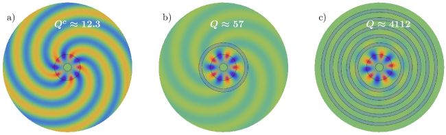
In this article, we propose a general procedure to reduce bending losses, which can readily be implemented with existing technologies. It consists of surrounding the circular cavity with properly designed concentric dielectric shells. These give control to the far-field amplitude and, hence, the radiation losses of WGM. The more external shells there is in the external structure, the stronger the reduction of bending losses can be obtained, with no apparent limit. As an example, we show an increase of the factor from 15 000 to 125 000, 600 000 and 2.5 106 with one, two or three external rings, respectively (here, and from now on, we restrict our attention to the radiative part of the factor.) In another, extreme case, we consider a WGM with orbital number and vacuum wavelength m in a cavity with m only. Starting from an initial quality factor , we obtain by adding five external shells, while keeping the WGM entirely within the cavity. The strongest suppression of radiation is generally obtained when the innermost external shell is at the transition where the WGM field switches between exponential (near field) and undulatory (far-field) behaviour. Conversely, if desired, the external structure can drastically enhance radiation losses and decrease . Hints that radiation losses could be controlled by such a structure were found by an analytical theory in the limit of large with a single outer shell Kozyreff and Acharyya (2016). Here, we provide a complete theory, that remains valid for small and which applies to any number of external shells. Previous authors have considered geometries that appear at first sight similar to what is considered here Li et al. (2009); Cai et al. (2015); Malmir et al. (2016); Chamorro-Posada (2017, ) (Note for proper comparison that the field circulates in the external ring in Ref. Malmir et al. (2016).) However, the present scheme is different in some fundamental aspects, which explains that the enhancement in reported here is orders of magnitudes larger that in previous works: An enhancement factor at most between 2 and 10 in Cai et al. (2015); Chamorro-Posada (2017) compared to more than 350 in some examples discussed here. In Refs. Li et al. (2009); Cai et al. (2015); Malmir et al. (2016); Chamorro-Posada (2017, ) the cavity is coupled to an external, curved waveguide, which effectively increases the radius of the ring. By contrast, the external rings considered in this Letter are too thin to act as waveguide and the field remains entirely confined inside the cavity. When it contains many shells, the present configuration becomes closer in spirit to Bragg fibres Yeh et al. (1978); Xu et al. (2000). However, we consider photons that circulate in a cavity rather than propagate along the axis of a Bragg fibre. In addition, in the optimal configuration, the first ring is always in the evanescent zone of the cavity and not in the radiation zone, a consideration that is evidently absent in the study of Bragg fibres.
II Theory
An analytical understanding of the radiation of a WGM resonator embedded in such a dielectric ‘sarcophagus’ can be obtained in 2D. In this framework, the knowledge of the electromagnetic field is entirely encoded in just one of its component, for transverse electric (TE) modes or for transverse magnetic (TM) modes. In an annulus defined by , of refractive index , the general form of is
| (1) |
where and are the usual polar coordinates, is the speed of light in vacuum, are Bessel functions of the first and second kind Abramowitz and Stegun (1972) and is the complex wave number. At surfaces of discontinuity of the refractive index, both and either (TE) or (TM) are continuous. These continuity relations can expressed as
| (2) |
where the are matrices containing combinations of Bessel functions evaluated at appropriate interfaces (see Supplementary Information.) By iterating the process, one may link the innermost and outermost coefficients of Eq. (1), giving
| (3) |
with . Above, we have imposed constraints on the combinations of Bessel functions near the origin and in the outermost region, namely to avoid divergence as and impose proper radiation condition in the far field. The second component of Eq. (3) directly yields the characteristic equation:
| (4) |
It has complex roots of the form , from which the quality factor can be deduced as . To study by direct resolution of Eq. (4) for each choice of geometrical parameter set rapidly becomes intractable as the number of outer rings increases. However, our aim here is to study the effect of the external structure on the radiation properties of the internal one, i.e. to compare with the complex wave number of the bare cavity. The latter is easier to compute, as it solves a simpler equation. Moreover, in the situations of interest, is by hypothesis not so small that it requires special numerical care. As the innermost layers of the whole guiding structures make up the bare cavity, we may write in Eq. (3) as , where and correspond to the cavity and the radiation shielding structure, respectively. By analogy with the above, satisfies the simpler equation
| (5) |
With , it must either be that, to leading order, and or that and . If the cavity is a simple disk, then it is easy to check that is precisely the sought-after characteristic equation. For more complicated geometries, we find that it is still so. This can be traced back to the fact that is on the order of which is a rapidly increasing function of Abramowitz and Stegun (1972). Hence, a complex resonance of the bare cavity is approximately given by
| (6) |
where prime denotes derivative. In the situations of interest here, not being very large, finding the root of does not pose a numerical challenge (for a large- treatment, see Kozyreff and Acharyya (2016).) Next, with , Eq. (4) yields
| (7) |
Focusing on the solutions that correspond to perturbed modes of the bare cavity, we note that , with . Expanding Eq. (7) near and exploiting Eq. (6), we obtain
| (8) |
where the elements on the right hand side are evaluated at the known value . Since , the change in quality factor that results from the external structure is found to be:
| (9) |
The advantage of the above expression is that it explicitly yields the ratio without having to solve the characteristic equation of the complete geometry. It proves to be extremely accurate for values of the orbital number (see Fig LABEL:figoneshell.) Even for does it predict the enhancement of to within fifteen percent. There has been a few previous works (see Kozyreff and Acharyya (2016) and references therein) to estimate the losses in the asymptotic cases of large circular orbital number . However, to our knowledge, an analytic formula such as Eq. (9) which is nearly exact has never been presented. The provided formula is very useful, particularly to optimise a shield with many shells where a numerical resolution of the characteristic equation is laborious. It enables us to circumvent the problems of solving the transcendental equation and merely requires evaluating the formula for various shield parameters.
The above analysis suggests a simple, layer-by-layer, design strategy. Starting form the bare cavity, one first considers a single outside shell with inner and outer radii and . To optimize the right-hand-side of Eq. (9) with respect to only two parameters and is a straightforward matter. The greatest single-step enhancement is usually seen with this first outer shell. While several local maxima in the gain are found, see Fig. LABEL:figoneshell, the global maximum is typically found near the turning point where the spatial field distribution switches from exponential to oscillating. Subsequent improvements are then achieved by optimizing the parameters of a second shell structure, followed by a third one, etc. To demonstrate this procedure, we first consider an Al2O3 ring cavity (refractive index ) in air environment. Al2O3 has been demonstrated to be an advantageous, CMOS compatible, host for rare-earth dopant and holds great potential to integrate micro-lasers in photonic platforms Bernhardi et al. (2010, 2011, 2012); Frankis et al. (2018). The bare ring cavity has inner and outer radii given by and m, respectively. We focus on the fundamental radial TE mode with orbital number , which corresponds to a wavelength m, in the emission band of Yb. Without a dielectric sarcophagus, . With a single shell with parameters m, an eight-fold increase of is obtained. Approximate four-fold increases are additionnally gained with a second and third shell with inner radii and thicknesses m, and m, respectively, eventually raising to (see Supplemental Information.) This last value is close to the current intrinsic limit of Al2O3. Interestingly, Fig. LABEL:figoneshell indicates that can also be significantly decreased for other configurations; in that case, WGM radiation is enhanced by the external structure.
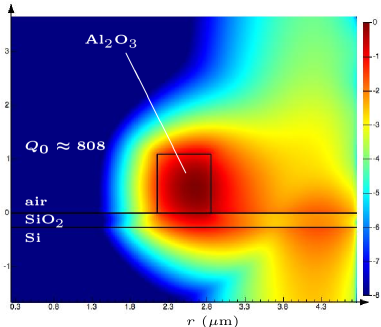
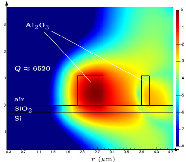
As a second example, we consider a ring cavity with only 1m outer radius and radial thickness m, operating at m, that is . Here, , which is unacceptably low compared to the state of the art. Adding five layers, of internal radii m of respective thicknesses m leads to , representing and enhancement by more than a factor 350. Fig. 2 shows the change in radiation intensity and demonstrates that the mode energy stays confined in the central part of the structure. Further improvement can be obtained with additional layers. We note in this example that the optimal value of is close to . It is expected that tends to that limit in the far-field, as the WGM locally tend to plane waves and the shield becomes equivalent to a Bragg reflector.
The above remark strongly suggests that the physical mechanism behind WGM radiation shielding is a kind of Bragg reflection by the external shells. Indeed, in the Supplementary Information, the shells are seen to nearly exactly contain a quarter of radial oscillation of in the optimal configuration, as with plane waves Wolf and Born (1980). There are two differences with respect to standard Bragg reflection, however. Firstly, the radial oscillation are not sinusoidal but governed by Bessel functions. Consequently, the radiation shield is not periodic and its design rest on a formula like Eq. (9). Secondly, and more fundamentally, the efficiency of the shield critically depends on where it is located -a feature that is obviously absent from standard Bragg reflection. Whereas the problem of reflection of plane waves is invariant by translation, the WGM cavity introduces an absolute reference point on the radial axis.
To illustrate this last point, let us resume the first example above, a bare Al2O3 cavity of external radius m operating on the azimuthal mode, with . If one now encircles the cavity with two external shells with m and m, one obtains , approximately corresponding to a 70-fold enhancement of the power radiated by the mode. Such a phenomenon can not be interpreted by simply picturing the external shells as a reflector. How the radial dependence of the field is affected by the shells is shown in the Supplemental Material.
III 3D simulations
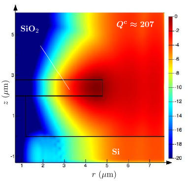
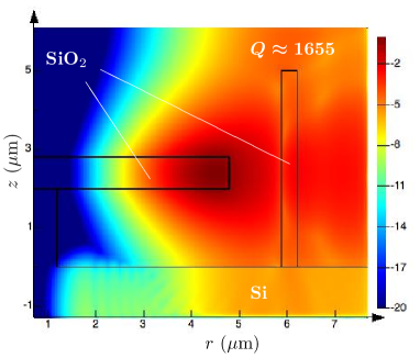
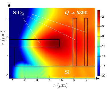
It is intuitively clear that, as far as radial confinement is concerned, the 2D picture provides a faithful representation of WGM, even in 3D. Indeed the WGM on a sphere with orbital number have a radial dependence, and a characteristic equation, again controlled by Bessel functions, albeit of order instead of Matsko and Ilchenko (2006). The WGM on a sphere can thus be mapped onto those of a an infinite cylinder and the two spectra coincide up to the transformation . On the other hand, spherical WGM can be strongly confined in the polar direction, with their intensity distribution confined in the immediate vicinity of the equator. Those particular WGM are almost unaffected if the sphere is truncated along parallel planes to the equator, which, in turn, is geometrically similar to a disk. Hence, we expect that 2D cylindrical WGM can serve as a reasonable qualitative model of WGM in ring and disk cavities of finite vertical height and that our finding can be transposed there. To check this assertion, we have performed 3D simulations of SiO2 disk cavities on a pilar over a Si foundation, as in Figure 3. Such a configuration, or similar ones, can be made using xenon difluoride (XeF2) etching through a silicon substrate Yang et al. (2018). Here again, we manage to obtain a nearly eight-fold enhancement with a single external shell. With a second external shell the initial can be improved further, up to a factor 26. This confirms both the fact that the quality factor can be increased by the design of an external shell and the fact that further enhancement can be obtained by additional shell. Hence, the gain reported in these 3D simulation should by no means be considered as ultimate ones.
Finally, in Fig. 4, we confirm the effect with a ridge waveguide ring cavity. Again, an eight-fold improvement of is obtained with a judiciously positioned external shell. Note that the vertical confinement renders possible the excitation of the cavity in the presence of the external shells. For instance, ridge-waveguide cavities can efficiently be excited with buried waveguides Su et al. (2018); Frankis et al. (2018).
IV Conclusions
In conclusion, we have devised a way to control one of the most basic limiting factor to WGM resonator performance. With existing fabrication techniques, radiation losses can in principle be reduced to any desired degree on integrated photonic platforms. In the ratio , the quality factor could thus be limited by material factors only and not by bending losses. This could pave the way to orders of magnitude improvement of performances in laser operation, sensing or cavity quantum electrodynamics experiments based on WGM.
Acknowledgements.
G.K. is a Research Associate of the Fonds de la Recherche Scientifique - FNRS (Belgium.) This research has received funding from the European Union’s Seventh Programme for research, technological development and demonstration under grant agreement No 634928 (GLAM project, http://www.glam-project.eu/).References
- Matsko and Ilchenko (2006) A. B. Matsko and V. S. Ilchenko, IEEE J. Sel. Topics Quantum Electon. 12, 3 (2006).
- Ilchenko and Matsko (2006) V. S. Ilchenko and A. B. Matsko, IEEE J. Sel. Topics Quantum Electon. 12, 15 (2006).
- Vollmer and Yan (2012) F. Vollmer and L. Yan, Nanophotonics 1, 267 (2012).
- Bogaerts et al. (2012) W. Bogaerts, P. De Heyn, T. Van Vaerenbergh, K. De Vos, S. Kumar Selvaraja, T. Claes, P. Dumon, P. Bienstman, D. Van Thourhout, and R. Baets, Laser & Photonics Reviews 6, 47 (2012).
- Foreman et al. (2015) M. R. Foreman, J. D. Swaim, and F. Vollmer, Advances in Optics and Photonics 7, 168 (2015).
- Vollmer et al. (2002) F. Vollmer, D. Braun, A. Libchaber, M. Khoshsima, I. Teraoka, and S. Arnold, Applied Physics Letters 80, 4057 (2002).
- Arnold et al. (2003) S. Arnold, M. Khoshsima, I. Teraoka, S. Holler, and F. Vollmer, Opt. Lett. 28, 272 (2003).
- Vos et al. (2007) K. D. Vos, I. Bartolozzi, E. Schacht, P. Bienstman, and R. Baets, Opt. Express 15, 7610 (2007).
- Washburn et al. (2010) A. L. Washburn, M. S. Luchansky, A. L. Bowman, and R. C. Bailey, Anal. Chem. 82, 69 (2010).
- Iqbal et al. (2010) M. Iqbal, M. A. Gleeson, B. Spaugh, F. Tybor, W. G. Gunn, M. Hochberg, T. Baehr-Jones, R. C. Bailey, and L. C. Gunn, IEEE J. Sel. Top. Quant. Electron. 16, 654 (2010).
- Luchansky and Bailey (2011) M. S. Luchansky and R. C. Bailey, Analytical Chemistry 84, 793 (2011).
- Washburn et al. (2016) A. L. Washburn, W. W. Shia, K. A. Lenkeit, S.-H. Lee, and R. C. Bailey, Analyst 141, 5358 (2016).
- Vollmer et al. (2008) F. Vollmer, S. Arnold, and D. Keng, Proc. Natl. Acad. Sci. USA 105, 20701 (2008).
- Lu et al. (2011) T. Lu, H. Lee, T. Chen, S. Herchak, J. Kim, S. Fraser, R. Flagan, and K. Vahala, Proc. Natl. Acad. Sci. USA 108, 5976 (2011).
- He et al. (2011) L. He, Ş. K. Özdemir, J. Zhu, W. Kim, and L. Yang, Nat. Nanotech. 6, 428 (2011).
- Dominguez-Juarez et al. (2011) J. L. Dominguez-Juarez, G. Kozyreff, and J. Martorell, Nat. Commun. 2, 254 (2011).
- Kozyreff et al. (2011) G. Kozyreff, J. L. Dominguez Juarez, and J. Martorell, Laser Photon. Rev. 5, 737 (2011).
- McCall et al. (1992) S. L. McCall, A. F. J. Levi, R. E. Slusher, S. J. Pearton, and R. A. Logan, Applied Physics Letters 60, 289 (1992).
- Sandoghdar et al. (1996) V. Sandoghdar, F. Treussart, J. Hare, V. Lefèvre-Seguin, J. M. Raimond, and S. Haroche, Physical Review A 54, R1777 (1996).
- Srinivasan et al. (2006) K. Srinivasan, M. Borselli, O. Painter, A. Stintz, and S. Krishna, Opt. Express 14, 1094 (2006).
- Kippenberg et al. (2004) T. J. Kippenberg, S. M. Spillane, and K. J. Vahala, Phys. Rev. Lett. 93, 083904 (2004).
- Ilchenko et al. (2004) V. S. Ilchenko, A. A. Savchenkov, A. B. Matsko, and L. Maleki, Phys. Rev. Lett. 92, 043903 (2004).
- Lin and Campillo (1994) H. B. Lin and A. J. Campillo, Physical Review Letters 73, 2440 (1994).
- Carmon and Vahala (2007) T. Carmon and K. J. Vahala, Nature Phys. 3, 430 (2007).
- Del’Haye et al. (2007) P. Del’Haye, A. Schliesser, O. Arcizet, T. Wilken, R. Holzwarth, and T. J. Kippenberg, Nature 450, 1214 (2007).
- Savchenkov et al. (2008) A. A. Savchenkov, A. B. Matsko, V. S. Ilchenko, I. Solomatine, D. Seidel, and L. Maleki, Phys. Rev. Lett. 101, 093902 (2008).
- Chembo and Yu (2010) Y. K. Chembo and N. Yu, Phys. Rev. A 82, 033801 (2010).
- Yi et al. (2015) X. Yi, Q.-F. Yang, K. Y. Yang, M.-G. Suh, and K. Vahala, Optica 2, 1078 (2015).
- Kozyreff et al. (2008) G. Kozyreff, J. L. Dominguez Juarez, and J. Martorell, Phys. Rev. A 77, 043817 (2008).
- Jouravlev and Kurizki (2004) M. V. Jouravlev and G. Kurizki, Phys. Rev. A 70, 053804 (2004).
- Fürst et al. (2010a) J. U. Fürst, D. V. Strekalov, D. Elser, M. Lassen, U. L. Andersen, C. Marquardt, and G. Leuchs, Phys. Rev. Lett. 104, 153901 (2010a).
- Fürst et al. (2010b) J. U. Fürst, D. V. Strekalov, D. Elser, A. Aiello, U. L. Andersen, C. Marquardt, and G. Leuchs, Phys. Rev. Lett. 105, 263904 (2010b).
- Fürst et al. (2011) J. U. Fürst, D. V. Strekalov, D. Elser, A. Aiello, U. L. Andersen, C. Marquardt, and G. Leuchs, Phys. Rev. Lett. 106, 113901 (2011).
- Vernooy et al. (1998) D. W. Vernooy, A. Furusawa, N. P. Georgiades, V. S. Ilchenko, and H. J. Kimble, Phys. Rev. A 57, R2293 (1998).
- Peter et al. (2005) E. Peter, P. Senellart, D. Martrou, A. Lemaître, J. Hours, J. M. Gérard, and J. Bloch, Phys. Rev. Lett. 95, 067401 (2005).
- Aoki et al. (2006) T. Aoki, B. Dayan, E. Wilcut, W. P. Bowen, A. S. Parkins, T. Kippenberg, K. Vahala, and H. Kimble, Nature 443, 671 (2006).
- Förtsch et al. (2013) M. Förtsch, J. U. Fürst, C. Wittmann, D. Strekalov, A. Aiello, M. V. Chekhova, C. Silberhorn, G. Leuchs, and C. Marquardt, Nat. Commun. 4, 1818 (2013).
- Özdemir et al. (2011) Ş. K. Özdemir, J. Zhu, L. He, and L. Yang, Phys. Rev. A 83, 033817 (2011).
- Savchenkov et al. (2007) A. A. Savchenkov, A. B. Matsko, V. S. Ilchenko, and L. Maleki, Opt. Express 15, 6768 (2007).
- Tien et al. (2011) M.-C. Tien, J. F. Bauters, M. J. R. Heck, D. T. Spencer, D. J. Blumenthal, and J. E. Bowers, Opt. Express 19, 13551 (2011).
- Spencer et al. (2014) D. T. Spencer, J. F. Bauters, M. J. R. Heck, and J. E. Bowers, Optica 1, 153 (2014).
- Hausmann et al. (2014) B. J. M. Hausmann, I. Bulu, V. Venkataraman, P. Deotare, and M. Lončar, Nat. Photon. 8, 369 (2014).
- Su et al. (2018) Z. Su, N. Li, H. C. Frankis, E. S. Magden, T. N. Adam, G. Leake, D. Coolbaugh, J. D. B. Bradley, and M. R. Watts, Opt. Express 26, 11161 (2018).
- Shitikov et al. (2018) A. E. Shitikov, I. A. Bilenko, N. M. Kondratiev, V. E. Lobanov, A. Markosyan, and M. L. Gorodetsky, Optica 5, 1525 (2018).
- Yang et al. (2018) K. Y. Yang, D. Y. Oh, S. H. Lee, Q.-F. Yang, X. Yi, B. Shen, H. Wang, and K. Vahala, Nature Photon. 12, 297 (2018).
- Kozyreff and Acharyya (2016) G. Kozyreff and N. Acharyya, Opt. Express 24, 28204 (2016).
- Li et al. (2009) X. Li, Z. Zhang, S. Qin, T. Wang, F. Liu, M. Qiu, and Y. Su, Appl. Opt. 48, F90 (2009).
- Cai et al. (2015) D.-P. Cai, J.-H. Lu, C.-C. Chen, C.-C. Lee, C.-E. Lin, and T.-J. Yen, Sci. Rep. 5, 10078 (2015).
- Malmir et al. (2016) K. Malmir, H. Habibiyan, and H. Ghafoorifard, Opt. Commun. 365, 150 (2016).
- Chamorro-Posada (2017) P. Chamorro-Posada, Opt. Commun. 387, 70 (2017).
- (51) P. Chamorro-Posada, arXiv:1802.04012v2 .
- Yeh et al. (1978) P. Yeh, A. Yariv, and E. Marom, J. Opt. Soc. Am. 68, 1196 (1978).
- Xu et al. (2000) Y. Xu, R. K. Lee, and A. Yariv, Opt. Lett. 25, 1756 (2000).
- Abramowitz and Stegun (1972) M. Abramowitz and I. A. Stegun, Handbooks of Mathematical Functions, 10th ed. (Dover, 1972).
- Bernhardi et al. (2010) E. Bernhardi, H. Van Wolferen, L. Agazzi, M. Khan, C. Roeloffzen, K. Wörhoff, M. Pollnau, and R. De Ridder, Opt. Lett. 35, 2394 (2010).
- Bernhardi et al. (2011) E. Bernhardi, H. van Wolferen, K. Wörhoff, R. De Ridder, and M. Pollnau, Opt. Lett. 36, 603 (2011).
- Bernhardi et al. (2012) E. Bernhardi, M. Khan, C. Roeloffzen, H. van Wolferen, K. Wörhoff, R. De Ridder, and M. Pollnau, Opt. Lett. 37, 181 (2012).
- Frankis et al. (2018) H. C. Frankis, Z. Su, N. Li, E. S. Magden, M. Ye, M. R. Watts, and J. D. Bradley, in CLEO: Science and Innovations (Optical Society of America, 2018) pp. STh3I–3.
- Wolf and Born (1980) E. Wolf and M. Born, Principles of Optics: Electromagnetic Theory of Propagation Interference and Diffraction of Light (Butterworth-Heinemann, 1980).