\NewEnviron

eqsplit[1]

\BODY\BODY\displaystyle\BODY (1a)
\excludeversion

checked \markversiondetail

A response function framework for the dynamics of
meandering or large-core spiral waves and modulated traveling waves

H. Dierckx Department of Physics and Astronomy, Ghent University, 9000 Ghent, Belgium    A. V. Panfilov Department of Physics and Astronomy, Ghent University, 9000 Ghent, Belgium Laboratory of Computational Biology and Medicine, Ural Federal University, Ekaterinburg, Russia    H. Verschelde Department of Physics and Astronomy, Ghent University, 9000 Ghent, Belgium    V.N. Biktashev College of Engineering, Mathematics and Physical Sciences, University of Exeter, Exeter EX4 4QF, UK    I.V. Biktasheva Department of Computer Science, University of Liverpool, Liverpool L69 3BX, UK College of Engineering, Mathematics and Physical Sciences, University of Exeter, Exeter EX4 4QF, UK
Abstract

In many oscillatory or excitable systems, dynamical patterns emerge which are stationary or periodic in a moving frame of reference. Examples include traveling waves or spiral waves in chemical systems or cardiac tissue. We present a unified theoretical framework for the drift of such patterns under small external perturbations, in terms of overlap integrals between the perturbation and the adjoint critical eigenfunctions of the linearised operator (i.e. ‘response functions’). For spiral waves, the finite radius of the spiral tip trajectory as well as spiral wave meander are taken into account. Different coordinates systems can be chosen, depending on whether one wants to predict the motion of the spiral wave tip, the time-averaged tip path, or the center of the meander flower. The framework is applied to analyse the drift of a meandering spiral wave in a constant external field in different regimes.

I Introduction

Spiral waves are remarkable self-sustained patterns which arise in various extended systems, including oscillating chemical reactions Jahnke et al. (1988), catalytic oxidation Nettesheim et al. (1993) and biological systems. In biology, spiral waves have been observed across vastly different spatial scales, as they organise intracellular calcium waves Lechleiter et al. (1991), slime mould aggregation Siegert and Weijer (1992), waves of spreading depression in the brain Gorelova and Bures (1983), and cardiac contraction during arrhythmic events Allessie et al. (1973); Gray et al. (1998); Witkowsky et al. (1998); Haissaguerre et al. (2014). In the context of cardiac arrhythmias, different drift regimes are thought to correspond to different heart rhythm disorders Gray et al. (1998). Moreover, tracking of rotation centers of cardiac rotors was shown to improve ablation therapies of atrial arrhythmias Narayan et al. (2012).

The development of asymptotic description of drift of spiral waves has been contingent on two important issues: localization of adjoint symmetry modes Biktasheva et al. (1998); Biktasheva and Biktashev (2001); Hakim and Henry (2002); Biktasheva et al. (2009); Marcotte and Grigoriev (2015); Dierckx et al. (2017a) and an appropirate choice of the drift system of reference Keener (1988); Biktashev et al. (1994); Biktasheva and Biktashev (2003); Biktasheva et al. (2010). On this pathway, the choice of an “optimal” system of reference naturally depends on the unpertubed spiral wave dynamics, i.e. whether it is (i) a rigidly rotating spiral wave with its tip following a perfect circle, (ii) a bi-periodic “meander” regime when the spiral wave periodically changes its shape and its tip describes a bi-periodic flower-like trajectory, or (iii) more complicated cases dubbed ‘hypermeander’. While the asymptotic theory of the drift of rigidly rotating spiral waves is the most advanced Biktasheva and Biktashev (2003); Biktasheva et al. (2010), the theory of hypermeander drift is the one least developed Biktashev and Holden (1998); Nicol et al. (2001); Ashwin et al. (2001). The current work aims to lay out a technical framework for the drift of a bi-periodic meander regime, and illustrate its application on a simple example of electroforetic drift.

The propagation of cardiac excitation, as well as many other systems in which spiral waves are observed, can be described by reaction-diffusion (RD) systems (see, e.g. Clayton et al. (2011)),

t𝐮=j[𝐏jk(r,t)k𝐮]+𝐅(𝐮,r,t).subscript𝑡𝐮subscript𝑗delimited-[]superscript𝐏𝑗𝑘𝑟𝑡subscript𝑘𝐮𝐅𝐮𝑟𝑡\displaystyle\partial_{t}{\color[rgb]{0,0,1}\mathbf{u}}=\partial_{{\color[rgb]{0,0,1}j}}\left[{\color[rgb]{0,0,1}{\mathbf{P}}}^{{\color[rgb]{0,0,1}j}{\color[rgb]{0,0,1}k}}({\color[rgb]{0,0,1}\vec{r}},{\color[rgb]{0,0,1}t})\partial_{{\color[rgb]{0,0,1}k}}{\color[rgb]{0,0,1}\mathbf{u}}\right]+{\color[rgb]{0,0,1}\mathbf{F}}({\color[rgb]{0,0,1}\mathbf{u}},{\color[rgb]{0,0,1}\vec{r}},{\color[rgb]{0,0,1}t}).

Here, 𝐮=𝐮(r,t)n𝐮𝐮𝑟𝑡superscript𝑛{\color[rgb]{0,0,1}\mathbf{u}}={\color[rgb]{0,0,1}\mathbf{u}}({\color[rgb]{0,0,1}\vec{r}},{\color[rgb]{0,0,1}t})\in\mathbb{R}^{\color[rgb]{0,0,1}n} is the list (column-vector) of n𝑛{\color[rgb]{0,0,1}n} state variables, 𝐮=(u1,,un)T𝐮superscriptsubscript𝑢1subscript𝑢𝑛missing-subexpressionmissing-subexpressionmissing-subexpressionmissing-subexpressionmissing-subexpressionmissing-subexpression𝑇{\color[rgb]{0,0,1}\mathbf{u}}=\left(\begin{array}[]{ccccccc}{\color[rgb]{0,0,1}u}_{1},\dots,{\color[rgb]{0,0,1}u}_{\color[rgb]{0,0,1}n}\end{array}\right)^{T}, e.g. the concentrations of reacting species, r=(xj)𝒟N𝑟superscript𝑥𝑗𝒟superscript𝑁{\color[rgb]{0,0,1}\vec{r}}=({\color[rgb]{0,0,1}x}^{\color[rgb]{0,0,1}j})\in{\color[rgb]{0,0,1}\mathcal{D}}\subset\mathbb{R}^{\color[rgb]{0,0,1}N} is the vector of Cartesian coordinates, N=1,2𝑁12{\color[rgb]{0,0,1}N}=1,2 or 3, and t𝑡{\color[rgb]{0,0,1}t} is time. The vector-function 𝐅:n×N+1n:𝐅superscript𝑛superscript𝑁1superscript𝑛{\color[rgb]{0,0,1}\mathbf{F}}:\mathbb{R}^{{\color[rgb]{0,0,1}n}}\times\mathbb{R}^{{\color[rgb]{0,0,1}N}+1}\rightarrow\mathbb{R}^{{\color[rgb]{0,0,1}n}} describes the local dynamics of state variables, e.g. the reaction rates. The space-time dependent matrix-tensor (𝐏jk):N+1n×n×N×N:superscript𝐏𝑗𝑘missing-subexpressionmissing-subexpressionmissing-subexpressionmissing-subexpressionmissing-subexpressionmissing-subexpressionsuperscript𝑁1superscript𝑛𝑛superscript𝑁𝑁\left(\begin{array}[]{ccccccc}{\color[rgb]{0,0,1}{\mathbf{P}}}^{{\color[rgb]{0,0,1}j}{\color[rgb]{0,0,1}k}}\end{array}\right):\mathbb{R}^{{\color[rgb]{0,0,1}N}+1}\to\mathbb{R}^{{\color[rgb]{0,0,1}n}\times{\color[rgb]{0,0,1}n}}\times\mathbb{R}^{{\color[rgb]{0,0,1}N}\times{\color[rgb]{0,0,1}N}} contains the diffusivities of the state variables on its diagonal (of which some may be vanishing). Non-diagonal terms of 𝐏𝐏{\color[rgb]{0,0,1}{\mathbf{P}}} are present in systems with cross-diffusion; see e.g. Ref. Biktashev and Tsyganov (2011) and Fig. 1(b).

The asymptotic description follows the paradigm that first an idealized mathematical situation is considered, which is an unbounded, perfectly stationary, homogeneous and isotropic medium governed by the isotropic reaction-diffusion equation (RDE)

t𝐮=𝐏Δ𝐮+𝐅(𝐮)subscript𝑡𝐮𝐏Δ𝐮𝐅𝐮\displaystyle\partial_{t}{\color[rgb]{0,0,1}\mathbf{u}}={\color[rgb]{0,0,1}{\mathbf{P}}}\Delta{\color[rgb]{0,0,1}\mathbf{u}}+{\color[rgb]{0,0,1}\mathbf{F}}({\color[rgb]{0,0,1}\mathbf{u}}) (2)

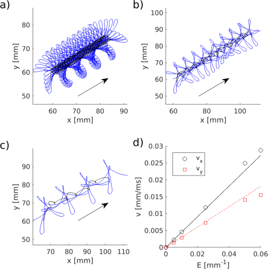
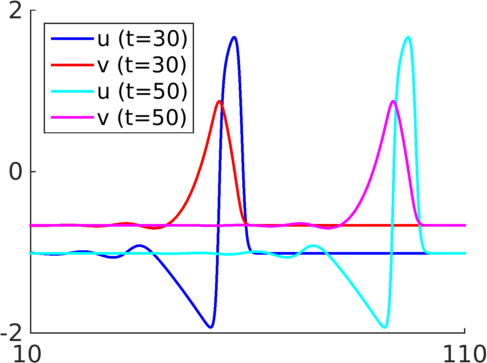
and then any deviations from the idealized picture are considered perturbatively. Here the diffusion matrix 𝐏𝐏{\color[rgb]{0,0,1}{\mathbf{P}}} is constant and the kinetic functions 𝐅(𝐮)𝐅𝐮{\color[rgb]{0,0,1}\mathbf{F}}({\color[rgb]{0,0,1}\mathbf{u}}) are taken uniform in space and time. In the context of pattern formation, a bistable, oscillatory or excitable point system is commonly used. For well-chosen sets of reaction kinetics, i.e. functions 𝐅(𝐮)𝐅𝐮{\color[rgb]{0,0,1}\mathbf{F}}({\color[rgb]{0,0,1}\mathbf{u}}), the system (2) may sustain waves of finite amplitude, which propagate through the medium, see Fig. 1(a–b).

Although our methodology works for any reaction-diffusion system allowing pattern formation, we will use below examples with the reaction kinetics of FitzHugh-Nagumo FitzHugh (1961); Biktasheva et al. (2009)

𝐏𝐏\displaystyle{\color[rgb]{0,0,1}{\mathbf{P}}} =diag(1,0),absentdiag10\displaystyle=\mathrm{diag}(1,0),
𝐅(𝐮)𝐅𝐮\displaystyle{\color[rgb]{0,0,1}\mathbf{F}}({\color[rgb]{0,0,1}\mathbf{u}}) =[α1(u1u13/3u2),α(u1γu2+β)]T,absentsuperscriptsuperscript𝛼1subscript𝑢1superscriptsubscript𝑢133subscript𝑢2𝛼subscript𝑢1𝛾subscript𝑢2𝛽𝑇\displaystyle=\left[{\color[rgb]{0,0,1}\alpha}^{-1}({\color[rgb]{0,0,1}u}_{1}-{\color[rgb]{0,0,1}u}_{1}^{3}/3-{\color[rgb]{0,0,1}u}_{2}),\quad{\color[rgb]{0,0,1}\alpha}({\color[rgb]{0,0,1}u}_{1}-{\color[rgb]{0,0,1}\gamma}{\color[rgb]{0,0,1}u}_{2}+{\color[rgb]{0,0,1}\beta})\right]^{T},

Barkley Barkley (1991)

𝐏𝐏\displaystyle{\color[rgb]{0,0,1}{\mathbf{P}}} =diag(1,0),absentdiag10\displaystyle=\mathrm{diag}(1,0),
𝐅(𝐮)𝐅𝐮\displaystyle{\color[rgb]{0,0,1}\mathbf{F}}({\color[rgb]{0,0,1}\mathbf{u}}) =[ς1u1(1u1)[u1(u2+b)/a],u1u2]Tabsentsuperscriptsuperscript𝜍1subscript𝑢11subscript𝑢1delimited-[]subscript𝑢1subscript𝑢2𝑏𝑎subscript𝑢1subscript𝑢2𝑇\displaystyle=\left[{\color[rgb]{0,0,1}\varsigma}^{-1}{\color[rgb]{0,0,1}u}_{1}(1-{\color[rgb]{0,0,1}u}_{1})[{\color[rgb]{0,0,1}u}_{1}-({\color[rgb]{0,0,1}u}_{2}+{\color[rgb]{0,0,1}b})/{\color[rgb]{0,0,1}a}],\quad{\color[rgb]{0,0,1}u}_{1}-{\color[rgb]{0,0,1}u}_{2}\right]^{T}

and Fenton and Karma. The equations and parameters of the latter model (with 3 state variables) are found in Fenton and Karma (1998).

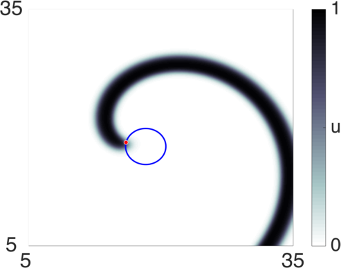
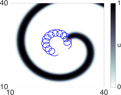
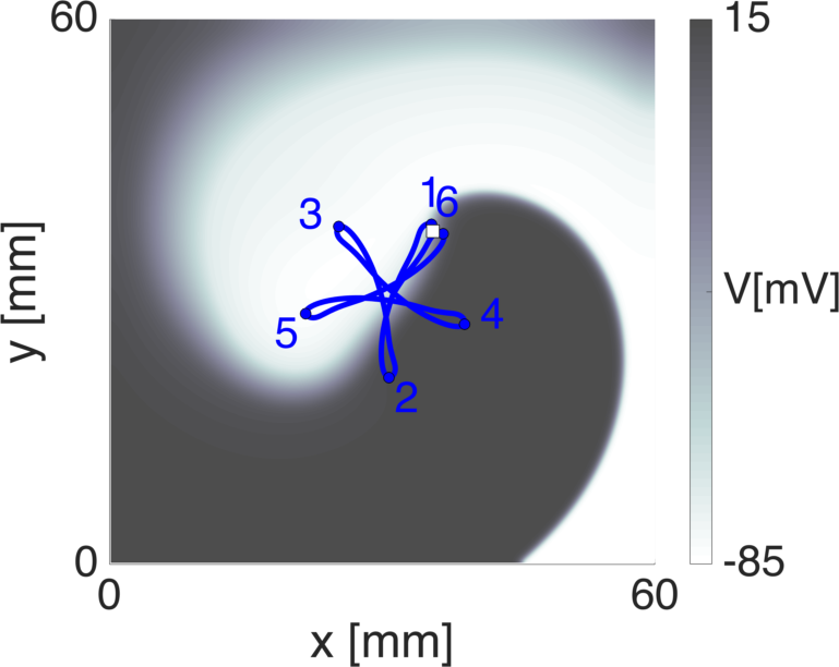
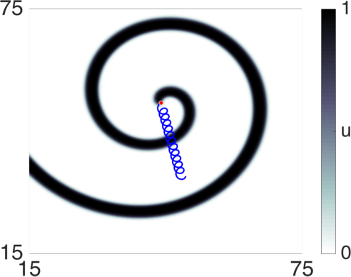
In N2𝑁2{\color[rgb]{0,0,1}N}\geq 2 spatial dimensions, the reaction-diffusion equation (2) may sustain rotating spiral-shaped solutions, as illustrated in Fig. 1(c–f). Spiral waves are commonly characterised by their tip trajectory, which can be found in different ways Zykov et al. (1997); Fenton and Karma (1998), e.g. as the locus where

uj(x,y,t)=uj,uk(x,y,t)=uk.formulae-sequencesubscript𝑢𝑗𝑥𝑦𝑡subscriptsuperscript𝑢𝑗subscript𝑢𝑘𝑥𝑦𝑡subscriptsuperscript𝑢𝑘\displaystyle{\color[rgb]{0,0,1}u}_{\color[rgb]{0,0,1}j}({\color[rgb]{0,0,1}x},{\color[rgb]{0,0,1}y},{\color[rgb]{0,0,1}t})={\color[rgb]{0,0,1}u^{*}_{{\color[rgb]{0,0,1}j}}},\qquad{\color[rgb]{0,0,1}u}_{\color[rgb]{0,0,1}k}({\color[rgb]{0,0,1}x},{\color[rgb]{0,0,1}y},{\color[rgb]{0,0,1}t})={\color[rgb]{0,0,1}u^{*}_{{\color[rgb]{0,0,1}k}}}. (3)

where j𝑗{\color[rgb]{0,0,1}j}, k𝑘{\color[rgb]{0,0,1}k} are indices of two selected state variables, jk𝑗𝑘{\color[rgb]{0,0,1}j}\neq{\color[rgb]{0,0,1}k}, and uj,uksubscriptsuperscript𝑢𝑗subscriptsuperscript𝑢𝑘{\color[rgb]{0,0,1}u^{*}_{{\color[rgb]{0,0,1}j}}},{\color[rgb]{0,0,1}u^{*}_{{\color[rgb]{0,0,1}k}}} are two appropriately chosen constants. In N=2𝑁2{\color[rgb]{0,0,1}N}=2 spatial dimensions, Eq. (3) means the intersection of isolines of two selected field components, where one isoline may correspond to a threshold level of the activator field, and the second condition separates the “front” and “back” parts of the first isoline based on the values of the inhibitor field. E.g. for Barkley kinetics, we use j=1,uj=0.5,k=2,u2=0.5abformulae-sequence𝑗1formulae-sequencesubscriptsuperscript𝑢𝑗0.5formulae-sequence𝑘2subscriptsuperscript𝑢20.5𝑎𝑏{\color[rgb]{0,0,1}j}=1,{\color[rgb]{0,0,1}u^{*}_{{\color[rgb]{0,0,1}j}}}=0.5,{\color[rgb]{0,0,1}k}=2,{\color[rgb]{0,0,1}u^{*}_{2}}=0.5a-b. It is often also convenient to take tuj=0subscript𝑡subscript𝑢𝑗0\partial_{\color[rgb]{0,0,1}t}{\color[rgb]{0,0,1}u}_{\color[rgb]{0,0,1}j}=0 as the second condition which corresponds to a point where the velocity of the activator isoline vanishes. Example tip trajectories are shown in Fig. 1(c–f). Another way of analysing spiral waves is by computing their phase, e.g. defined as a polar angle χ𝜒{\color[rgb]{0,0,1}\chi} in a suitably chosen plane in the phase space of local kinetics:

tanχ(r,t)=uk(r,t)ukuj(r,t)uj,𝜒𝑟𝑡subscript𝑢𝑘𝑟𝑡subscriptsuperscript𝑢𝑘subscript𝑢𝑗𝑟𝑡subscriptsuperscript𝑢𝑗\displaystyle\tan{\color[rgb]{0,0,1}\chi}({\color[rgb]{0,0,1}\vec{r}},{\color[rgb]{0,0,1}t})=\frac{{\color[rgb]{0,0,1}u}_{\color[rgb]{0,0,1}k}({\color[rgb]{0,0,1}\vec{r}},{\color[rgb]{0,0,1}t})-{{\color[rgb]{0,0,1}u^{*}_{{\color[rgb]{0,0,1}k}}}}}{{\color[rgb]{0,0,1}u}_{\color[rgb]{0,0,1}j}({\color[rgb]{0,0,1}\vec{r}},{\color[rgb]{0,0,1}t})-{{\color[rgb]{0,0,1}u^{*}_{{\color[rgb]{0,0,1}j}}}}}, (4)

This mapping will produce a phase singularity (PS) in the vicinity of the spiral tip Clayton et al. (2005). If j,k,uj,uk𝑗𝑘subscriptsuperscript𝑢𝑗subscriptsuperscript𝑢𝑘{\color[rgb]{0,0,1}j},{\color[rgb]{0,0,1}k},{\color[rgb]{0,0,1}u^{*}_{{\color[rgb]{0,0,1}j}}},{\color[rgb]{0,0,1}u^{*}_{{\color[rgb]{0,0,1}k}}} are set to the same values in Eqs. (3) and (4), the PS coincides with the spiral wave tip definition. Otherwise, different observers will generally not exactly agree on the tip or phase singularity position Gray et al. (2009).

In three spatial dimensions, the solution to the reaction-diffusion equation (2) consisting of a stack of spiral waves is known as a ‘scroll wave’. When tracking the scroll wave’s tip or PS, Eqs. (3) and (4) produce a curve that is known as the ‘scroll wave filament’. The same remark as in 2D holds here: different algorithms and chosen thresholds will yield different filament curves, which generally lie in each other’s vicinity, i.e. in the tubular scroll wave core region.

a) Refer to caption b) Refer to caption Refer to caption c) Refer to caption
d) Refer to caption e) Refer to caption f) Refer to caption

Figure 1: Qualitatively different one- and two-dimensional patterns that arise as solutions to the reaction-diffusion equation (2), depending on the chosel reaction model 𝐅(𝐮)𝐅𝐮{\color[rgb]{0,0,1}\mathbf{F}}({\color[rgb]{0,0,1}\mathbf{u}}) and initial conditions. a) Stationary traveling wave in the FitzHugh-Nagumo model FitzHugh (1961) (α=0.3𝛼0.3{\color[rgb]{0,0,1}\alpha}=0.3, β=0.68𝛽0.68{\color[rgb]{0,0,1}\beta}=0.68, γ=0.5𝛾0.5{\color[rgb]{0,0,1}\gamma}=0.5). b) Modulated 1D traveling wave in the FitzHugh-Nagumo model with cross-diffusion, shown at t=3000𝑡3000{\color[rgb]{0,0,1}t}=3000 and t=5000𝑡5000{\color[rgb]{0,0,1}t}=5000; reproduced from Biktashev and Tsyganov (2011). c) Rigidly rotating spiral wave in Barkley’s model Barkley (1991) (a=0.52𝑎0.52{\color[rgb]{0,0,1}a}=0.52, b=0.05𝑏0.05{\color[rgb]{0,0,1}b}=0.05, ς=0.02𝜍0.02{\color[rgb]{0,0,1}\varsigma}=0.02). d) Spiral wave with Barkley kinetics exhibiting flower-like meander with inward petals (a=0.58𝑎0.58{\color[rgb]{0,0,1}a}=0.58, b=0.05𝑏0.05{\color[rgb]{0,0,1}b}=0.05, ς=0.02𝜍0.02{\color[rgb]{0,0,1}\varsigma}=0.02). e) Meandering spiral wave with a linear-core in the Fenton-Karma Guinea Pig cardiac tissue model Fenton and Karma (1998). Labels indicate the order in which petals are visited. f) Spontaneous spiral wave drift in the case of resonant meander, in Barkley’s model (a=0.625𝑎0.625{\color[rgb]{0,0,1}a}=0.625, b=0.05𝑏0.05{\color[rgb]{0,0,1}b}=0.05, ς=0.02𝜍0.02{\color[rgb]{0,0,1}\varsigma}=0.02).

However, if the tip trajectory is circular, all tip paths and PS trajectories will in 2D describe circles around a unique rotation center 𝒞𝒞{\color[rgb]{0,0,1}\mathcal{C}} at the same angular frequency ω𝜔{\color[rgb]{0,0,1}\omega}. In previous works, the dynamics of circular-core spiral waves have been analysed in terms of the motion of the rotation center 𝒞𝒞{\color[rgb]{0,0,1}\mathcal{C}} Verschelde et al. (2007); Biktashev et al. (2010); Dierckx et al. (2012, 2013). For circular tip paths, the region inside it never excites and is sometimes called the ‘spiral wave core’. The dynamics of circular-core spiral waves is reasonably well understood, and their drift response to small external stimuli can be found by projecting the stimulus on the inertial manifold of the system using so-called ‘response functions’ Keener (1988); Biktashev and Holden (1995); Biktasheva and Biktashev (2003); Panfilov and Dierckx (2017).

Interestingly, in several experiments and numerical simulations, both in chemical Winfree (1973); Steinbock et al. (1993) and biological Haissaguerre et al. (2014); Yamazaki et al. (2012); Efimov et al. (1995); Courtemanche et al. (1998); Biktashev and Holden (1996); Fenton and Karma (1998); Bueno-Orovio et al. (2008) systems, the spiral wave was found to perform not a rigid rotation, but a more complicated motion, a phenomenon known as ‘spiral wave meander’ Rössler and Kahlert (1979); Zykov (1986); Winfree (1990). In excitable models, meander can arise due to the wave front interacting with the wave back from the previous excitation. In the simpler cases, the meander is quasi-periodic, in the sense that the evolution is periodic up to a Euclidean transformation. This transformation can always be written as a pure rotation or a pure translation (see below), which is why one can refer to it as ‘biperiodic’ meander, even when the tip trajectory is not a superposition of two circular motions. In more complicated cases, often called “hypermeander” Winfree (1990), the tip motion can have more than two periods Nicol et al. (2001) or be chaotic, resulting in deterministic Brownian motion of the tip position Biktashev and Holden (1998); we will not consider such cases here.

A significant step in understanding meander of spiral waves was made by Barkley et al. Barkley et al. (1990) and Karma Karma (1990), who showed that the transition to meander from the circular-core case exhibits typical features of a Hopf bifurcation. Barkley Barkley (1994) then showed that the process can be described by a set of five coupled ordinary differential equations. As a result, a tip trajectory is formed that is a superposition of two circular rotations, making a flower-like tip trajectory. This picture was put on constructive footing in Wulff (1996a); Fiedler et al. (1996); Golubitsky et al. (1997); Sandstede et al. (1997), using “skew-product” representation of the reaction-diffusion system exploiting its symmetry with respect to Euclidean motions of the plane. These works described the equivariant Hopf bifurcation (i.e. the regime close to the transition to meander), while many chemical and cardiac models show a qualitatively different tip trajectory, i.e. zig-zagged, star-like path known also as the “linear core” case. It turned out, however, that skew-product representation does not need to be restricted to the vicinity of the transition zone, and the more complicated meander pattern can be described as relative periodic solutions not necessarily related to a Hopf bifurcation Biktashev et al. (1996); Foulkes and Biktashev (2010).

Correspondingly, evolution of biperiodically meandering spirals, both flower-like and star-like, in response to small perturbations, can be analysed by linearising the system around a relative periodic orbit Dierckx et al. (2017a). To show the steps of this process in detail is the purpose of this manuscript; it extends the procedure for rigidly rotating spirals found in e.g. Biktashev and Holden (1995); Biktasheva and Biktashev (2003); Biktasheva et al. (2009). Since periodically deforming waves in one spatial dimension are obtained as a special case, we also describe their dynamics.

A significant part of this paper will be dealing with introducing different coordinate systems that are suitable to capture the drift dynamics of solutions to the RDE (2) because, depending on which definition of filament one adopts one can obtain simple or complex laws of motion. These laws can be further simplified if one averages in time over rotation cycles of the spiral or scroll waves Biktashev and Holden (1995). For non-stationary spiral or scroll waves, a possible averaging method is to analyse the motion in a Fourier series and only keep the non-oscillating, secularly growing terms Dierckx and Verschelde (2013); Dierckx et al. (2017b). Some recent works have computed the leading order eigenmodes in the laboratory frame of reference Marcotte and Grigoriev (2015, 2016). At the end, different descriptions need to be compatible, and it is our aim to illustrate that they all describe the same dynamics.

This paper is organised as follows. In Sec. II we discuss the concept of symmetry breaking by the formed patterns, which will determine the number of degrees of freedom required to uniquely describe such patterns. We first illustrate this concept in Sec. III on traveling waves in one dimension, treating the cases of rigidly moving and periodically deforming waves. In Sec. IV we consider spiral wave patterns in two spatial dimensions, in the regimes of rigid rotation, meander and resonant meander. We consider in detail multiple possible frames of reference, which are defined with respect to either instantaneous or time-averaged dynamics. In Sec. V we linearise around the solution and discuss the critical eigenmodes of the system. This knowledge is used in Sec. VI to derive the equations of motion for modulated wave patterns, in a manner that is valid for both traveling and spiral waves. In Sec. VII we re-interpret our approach in terms of the geometry of the phase space of the reaction-diffusion system considerd as a dynamical system. This part is optional, but we found it useful to include as few works make the connection between the ‘physics’ style of description and the more abstract dynamical systems viewpoint.

In Sec. VIII the drift response of a spiral wave in a constant external vector field is analysed. We show how the dynamics can be averaged over rotation and temporal phases in order to find a simpler, manageable equation of motion. In particular, we demonstrate that if a meandering spiral wave is phase-locked to a constant external field of magnitude E𝐸E, its drift velocity can be larger than order E𝐸E: it is close to the ‘orbital velocity’ which which the spiral wave circumscribes the meander flower.

We conclude with a discussion of our present work in Sec. IX. To assist the reader in remembering the notations used, we provide a list of notations in the Appendix.

II Symmetry considerations

It is customary to consider Eq. (2) in a bounded spatial domain with Neumann boundary conditions, which agrees with many physical situation where such models are relevant, and this is used in all numerical simulations of this work. However, to develop the theory of symmetry-breaking, we here consider the whole space Nsuperscript𝑁\mathbb{R}^{\color[rgb]{0,0,1}N}, with N=1𝑁1{\color[rgb]{0,0,1}N}=1 for wave fronts and N=2𝑁2{\color[rgb]{0,0,1}N}=2 for spiral waves. The two sets of boundary conditions do not need to conflict, as numerical evidence in various reaction-diffusion patterns Biktasheva et al. (1998); Biktasheva and Biktashev (2001); Hakim and Henry (2002); Biktasheva et al. (2009); Marcotte and Grigoriev (2015); Dierckx et al. (2017b) shows that the sensitivity of patterns to external stimuli, including boundary conditions, is strongly localised. The mathematical condition for this is that the adjoint critical eigenfunctions (‘response functions’ Biktasheva and Biktashev (2003)) 𝐖Msuperscript𝐖𝑀{\color[rgb]{0,0,1}\mathbf{W}}^{\color[rgb]{0,0,1}M} defined in Eqs. (18) below decay exponentially far from the wave front (in 1 spatial dimension) or far from the spiral wave tip (in 2 spatial dimensions). Therefore, faraway boundaries are not felt at e.g. the wave front or spiral tip.

Since the system (2) involves the spatial variables only via the Laplacian ΔΔ\Delta in the whole space Nsuperscript𝑁\mathbb{R}^{\color[rgb]{0,0,1}N}, it is equivariant (symmetric) with respect to the isometric transformations γ:NN:𝛾superscript𝑁superscript𝑁{\color[rgb]{0,0,1}\gamma}:\mathbb{R}^{\color[rgb]{0,0,1}N}\to\mathbb{R}^{\color[rgb]{0,0,1}N} of this space, meaning that if u(r,t)𝑢𝑟𝑡{\color[rgb]{0,0,1}u}({\color[rgb]{0,0,1}\vec{r}},{\color[rgb]{0,0,1}t}) is a solution, then u~(r,t)=u(γ1r,t)~𝑢𝑟𝑡𝑢superscript𝛾1𝑟𝑡{\tilde{{\color[rgb]{0,0,1}u}}}({\color[rgb]{0,0,1}\vec{r}},{\color[rgb]{0,0,1}t})={\color[rgb]{0,0,1}u}({\color[rgb]{0,0,1}\gamma}^{-1}{\color[rgb]{0,0,1}\vec{r}},{\color[rgb]{0,0,1}t}) is also a solution, for any isometry γ𝛾{\color[rgb]{0,0,1}\gamma}. For our purposes it is sufficient to consider only the orientation-preserving transformations, that is, γSE(N)𝛾SE𝑁{\color[rgb]{0,0,1}\gamma}\in{\color[rgb]{0,0,1}\mathrm{SE}({\color[rgb]{0,0,1}N})}. Besides, being autonomous, this system is equivariant with respect to the group of translations of the time axis, SE(1)similar-toSE1{\color[rgb]{0,0,1}\mathrm{SE}(1)}\sim\mathbb{R}, that is if u(r,t)𝑢𝑟𝑡{\color[rgb]{0,0,1}u}({\color[rgb]{0,0,1}\vec{r}},{\color[rgb]{0,0,1}t}) is a solution, then u~(r,t)=u(r,tT)~𝑢𝑟𝑡𝑢𝑟𝑡𝑇{\tilde{{\color[rgb]{0,0,1}u}}}({\color[rgb]{0,0,1}\vec{r}},{\color[rgb]{0,0,1}t})={\color[rgb]{0,0,1}u}({\color[rgb]{0,0,1}\vec{r}},{\color[rgb]{0,0,1}t}-{\color[rgb]{0,0,1}T}) is also a solution for any T𝑇{\color[rgb]{0,0,1}T}\in\mathbb{R}. (Note that this is different from saying the solution is ‘invariant’ with respect to time translation, which would imply a solution that is constant in time.) Thus, we can say overall that (2) is symmetric with respect to the inhomogeneous Galilean group G=SE(N)×𝐺SE𝑁{\color[rgb]{0,0,1}G}={\color[rgb]{0,0,1}\mathrm{SE}({\color[rgb]{0,0,1}N})}\times\mathbb{R}. The dimensionality of this Lie group is dim(G)=N(N+1)/2+1dimension𝐺𝑁𝑁121\dim({\color[rgb]{0,0,1}G})={\color[rgb]{0,0,1}N}({\color[rgb]{0,0,1}N}+1)/2+1.

Any given solution u(r,t)𝑢𝑟𝑡{\color[rgb]{0,0,1}u}({\color[rgb]{0,0,1}\vec{r}},{\color[rgb]{0,0,1}t}) of Eq. (2) may be invariant with respect to none, or all, or part of the symmetries of the equation itself. Invariance of the solution with respect to a purely spatial symmetry γSE(N)𝛾SE𝑁{\color[rgb]{0,0,1}\gamma}\in{\color[rgb]{0,0,1}\mathrm{SE}({\color[rgb]{0,0,1}N})} can in general be reduced to a lower-dimensional solution and is not further considered. E.g. a plane wave in N=2𝑁2{\color[rgb]{0,0,1}N}=2, which is invariant for translations along the wave front. This case can be reduced to the study of a traveling wave in N=1𝑁1{\color[rgb]{0,0,1}N}=1 spatial dimension. An interesting case arises when a solution is invariant with respect to a spatiotemporal symmetry. E.g. for a rigidly translating traveling wave in N=1𝑁1{\color[rgb]{0,0,1}N}=1 at constant speed c𝑐{\color[rgb]{0,0,1}c}, 𝐮(r+cT,t+T)=𝐮(r,t)𝐮𝑟𝑐𝑇𝑡𝑇𝐮𝑟𝑡{\color[rgb]{0,0,1}\mathbf{u}}({\color[rgb]{0,0,1}\vec{r}}+{\color[rgb]{0,0,1}c}{\color[rgb]{0,0,1}T},{\color[rgb]{0,0,1}t}+{\color[rgb]{0,0,1}T})={\color[rgb]{0,0,1}\mathbf{u}}({\color[rgb]{0,0,1}\vec{r}},{\color[rgb]{0,0,1}t}) for any T𝑇{\color[rgb]{0,0,1}T}, which implies that there are members of G𝐺{\color[rgb]{0,0,1}G} that leave the solution invariant.

Let the group of symmetries leaving a solution invariant be H𝐻{\color[rgb]{0,0,1}H}, HG𝐻𝐺{\color[rgb]{0,0,1}H}\leq{\color[rgb]{0,0,1}G}. If this is also a Lie group, then application of all possible transformations γG𝛾𝐺{\color[rgb]{0,0,1}\gamma}\in{\color[rgb]{0,0,1}G} to u(r,t)𝑢𝑟𝑡{\color[rgb]{0,0,1}u}({\color[rgb]{0,0,1}\vec{r}},{\color[rgb]{0,0,1}t}) will produce a manifold of solutions, of dimensionality NBS=dimGdimHsubscript𝑁𝐵𝑆dimension𝐺dimension𝐻{\color[rgb]{0,0,1}N_{BS}}=\dim{\color[rgb]{0,0,1}G}-\dim{\color[rgb]{0,0,1}H}. We refer to this dimensionality as the number of broken symmetries (implying that the “unbroken ones” are in the subgroup H𝐻{\color[rgb]{0,0,1}H}). By construction, the tangent vectors to this manifold of solutions are solutions of the (2) linearised on u(r,t)𝑢𝑟𝑡{\color[rgb]{0,0,1}u}({\color[rgb]{0,0,1}\vec{r}},{\color[rgb]{0,0,1}t}) which do not exponentially grow or decay with time, so they make the center subspace of this solution. If the solution is an attractor to the system, this manifold of solutions will be called an ‘inertial manifold’, see details in Sec. VII.

In the following text, it will sometimes be convenient to indicate for every quantity, e.g. wave front or tip coordinates, the reference frame in which it is defined, using different math accents. We shall call the ‘simplest’ frame that makes the solution constant or periodic the center frame of reference. For any quantity f𝑓{\color[rgb]{0,0,1}f}, its value pertaining to this frame of reference, will be denoted as f𝑓\overset{\circ}{{\color[rgb]{0,0,1}f}}. The frame which best follows the wave front or spiral wave tip will be called the ’tip frame‘, with the corresponding notation fˇˇ𝑓\check{{\color[rgb]{0,0,1}f}}. An list of all notations and symbols used throughout this manuscript is given in the appendix.

III One-dimensional traveling waves

III.1 General framework

Let us first consider a generic choice for the frame of reference to describe a traveling wave 𝐔(x,t)𝐔𝑥𝑡{\color[rgb]{0,0,1}\mathbf{U}}({\color[rgb]{0,0,1}x},{\color[rgb]{0,0,1}t}). We denote the origin of the lab frame with Cartesian coordinate x𝑥x as O𝑂{\color[rgb]{0,0,1}{O}}. In the lab frame, we can define the wave front position x=𝒵(t)𝑥𝒵𝑡{\color[rgb]{0,0,1}x}={\color[rgb]{0,0,1}\mathcal{Z}}({\color[rgb]{0,0,1}t}) by thresholding a state variable uj(𝒵(t),t)=ujsubscript𝑢𝑗𝒵𝑡𝑡subscriptsuperscript𝑢𝑗{\color[rgb]{0,0,1}u}_{\color[rgb]{0,0,1}j}({\color[rgb]{0,0,1}\mathcal{Z}}({\color[rgb]{0,0,1}t}),{\color[rgb]{0,0,1}t})={{\color[rgb]{0,0,1}u^{*}_{{\color[rgb]{0,0,1}j}}}} and demanding that tuj(𝒵(t),t)>0subscript𝑡subscript𝑢𝑗𝒵𝑡𝑡0\partial_{\color[rgb]{0,0,1}t}{\color[rgb]{0,0,1}u}_{\color[rgb]{0,0,1}j}({\color[rgb]{0,0,1}\mathcal{Z}}({\color[rgb]{0,0,1}t}),{\color[rgb]{0,0,1}t})>0 to distinguish it from the wave back. This is one possible definition for the wave front position as a moving point 𝒵(t)𝒵𝑡{\color[rgb]{0,0,1}\mathcal{Z}}({\color[rgb]{0,0,1}t}), with lab frame coordinate x=Z(t)𝑥𝑍𝑡{\color[rgb]{0,0,1}x}={\color[rgb]{0,0,1}Z}({\color[rgb]{0,0,1}t}). However, alternative definitions are possible, e.g. for the wave shown in Fig. 1(b) the barycentre of |u2|2superscriptsubscript𝑢22|{\color[rgb]{0,0,1}u}_{2}|^{2} was used to denote wave position.

traveling wave type NBSSsubscript𝑁𝐵𝑆𝑆{\color[rgb]{0,0,1}N_{BSS}} NBTSsubscript𝑁𝐵𝑇𝑆{\color[rgb]{0,0,1}N_{BTS}} NBSsubscript𝑁𝐵𝑆{\color[rgb]{0,0,1}N_{BS}} Frame name Origin Choice Frame velocity
any 1 0 or 1 1 or 2 lab fixed 𝒳=O𝒳𝑂{\color[rgb]{0,0,1}\mathcal{X}}={\color[rgb]{0,0,1}{O}} c=0𝑐0{\color[rgb]{0,0,1}c}=0
 rigidly moving front 1 0 1 co-moving at front 𝒳=𝒵𝒳𝒵{\color[rgb]{0,0,1}\mathcal{X}}={\color[rgb]{0,0,1}\mathcal{Z}} c=cf𝑐subscript𝑐𝑓{\color[rgb]{0,0,1}c}={\color[rgb]{0,0,1}c_{f}}
periodically modulated front 1 1 2 fully co-moving at front 𝒳=𝒵𝒳𝒵{\color[rgb]{0,0,1}\mathcal{X}}={\color[rgb]{0,0,1}\mathcal{Z}} c(Ψ)=cf(Ψ)𝑐Ψsubscript𝑐𝑓Ψ{\color[rgb]{0,0,1}c}({\color[rgb]{0,0,1}\Psi})={\color[rgb]{0,0,1}c_{f}}({\color[rgb]{0,0,1}\Psi})
constant-speed co-moving frame near front 𝒳𝒵𝒳𝒵{\color[rgb]{0,0,1}\mathcal{X}}\neq{\color[rgb]{0,0,1}\mathcal{Z}} c=cf(Ψ)¯=const𝑐¯subscript𝑐𝑓Ψconst{\color[rgb]{0,0,1}c}=\overline{{\color[rgb]{0,0,1}c_{f}}({\color[rgb]{0,0,1}\Psi})}=\mathrm{const}
Table 1: Overview of reference frames used in the text to describe the motion of 1D traveling wave patterns. NBSSsubscript𝑁𝐵𝑆𝑆{\color[rgb]{0,0,1}N_{BSS}}: number of broken spatial continuous symmetries, NBTSsubscript𝑁𝐵𝑇𝑆{\color[rgb]{0,0,1}N_{BTS}}: number of broken temporal continuous symmetries, NBS=NBSS+NBTSsubscript𝑁𝐵𝑆subscript𝑁𝐵𝑆𝑆subscript𝑁𝐵𝑇𝑆{\color[rgb]{0,0,1}N_{BS}}={\color[rgb]{0,0,1}N_{BSS}}+{\color[rgb]{0,0,1}N_{BTS}}: number of broken continuous symmetries, O𝑂{\color[rgb]{0,0,1}{O}}: lab frame origin, 𝒵𝒵{\color[rgb]{0,0,1}\mathcal{Z}}: instantaneous wavefront position, 𝒳𝒳{\color[rgb]{0,0,1}\mathcal{X}}: chosen origin of the moving frame, cfsubscript𝑐𝑓{\color[rgb]{0,0,1}c_{f}}: speed of the wave front in the lab frame, ΨΨ{\color[rgb]{0,0,1}\Psi}: temporal phase describing the progression of the solution along a deformation cycle (relative periodic orbit).

Next, we introduce a (yet unspecified) moving frame of reference with origin 𝒳𝒳{\color[rgb]{0,0,1}\mathcal{X}} that has lab frame coordinate X(t)𝑋𝑡{\color[rgb]{0,0,1}{\color[rgb]{0,0,1}X}}(t) and denote the new spatial coordinate in the moving frame as ρ𝜌{\color[rgb]{0,0,1}\rho}:

ρ𝜌\displaystyle{\color[rgb]{0,0,1}\rho} =xX(t),absent𝑥𝑋𝑡\displaystyle={\color[rgb]{0,0,1}x}-{\color[rgb]{0,0,1}{\color[rgb]{0,0,1}X}}({\color[rgb]{0,0,1}t}), t𝑡\displaystyle\qquad{\color[rgb]{0,0,1}t} =τ.absent𝜏\displaystyle={\color[rgb]{0,0,1}\tau}. (5)

The moving frame can be chosen in different manners; an overview is given in Tab. 1.

The instantaneous wave front position is denoted Z(t)𝑍𝑡{\color[rgb]{0,0,1}Z}({\color[rgb]{0,0,1}t}), it is found at the position ρ=ζ(t)𝜌𝜁𝑡{\color[rgb]{0,0,1}\rho}={\color[rgb]{0,0,1}\zeta}({\color[rgb]{0,0,1}t}) in the moving frame:

Z(t)=X(t)+ζ(t).𝑍𝑡𝑋𝑡𝜁𝑡\displaystyle{\color[rgb]{0,0,1}Z}({\color[rgb]{0,0,1}t})={\color[rgb]{0,0,1}{\color[rgb]{0,0,1}X}}({\color[rgb]{0,0,1}t})+{\color[rgb]{0,0,1}\zeta}({\color[rgb]{0,0,1}t}).

III.2 Symmetry breaking

In a one-dimensional homogenous spatial domain (N=1𝑁1{\color[rgb]{0,0,1}N}=1), the RDE (2) is invariant with respect to translation in time and space, i.e. G×similar-to𝐺{\color[rgb]{0,0,1}G}\sim\mathbb{R}\times\mathbb{R}, and dim(G)=2dimension𝐺2\dim({\color[rgb]{0,0,1}G})=2. A traveling-wave solution does not have translational symmetry, neither in time nor space, so we can say it breaks the translational symmetry. However, if the wave travels with constant speed cfsubscript𝑐𝑓{\color[rgb]{0,0,1}c_{f}} without changing its shape, then we can say that u(xX,tT)=u(x,t)𝑢𝑥𝑋𝑡𝑇𝑢𝑥𝑡{\color[rgb]{0,0,1}u}({\color[rgb]{0,0,1}x}-{\color[rgb]{0,0,1}X},{\color[rgb]{0,0,1}t}-{\color[rgb]{0,0,1}T})={\color[rgb]{0,0,1}u}({\color[rgb]{0,0,1}x},{\color[rgb]{0,0,1}t}) as long as X𝑋{\color[rgb]{0,0,1}X} and T𝑇{\color[rgb]{0,0,1}T} are related by X=cfT𝑋subscript𝑐𝑓𝑇{\color[rgb]{0,0,1}X}={\color[rgb]{0,0,1}c_{f}}{\color[rgb]{0,0,1}T}. That means, that the solution is invariant with respect to a one-parametric group of transformations, so dimH=1dimension𝐻1\dim{\color[rgb]{0,0,1}H}=1, and NBS=1subscript𝑁𝐵𝑆1{\color[rgb]{0,0,1}N_{BS}}=1. This is the case of rigidly translating waves, to be treated in subsection III.3. However, if there is no frame of reference moving with constant speed in which the solution is constant in time, then the subgroup H𝐻{\color[rgb]{0,0,1}H} is trivial or at most discrete, so dimH=0dimension𝐻0\dim{\color[rgb]{0,0,1}H}=0, and NBS=2subscript𝑁𝐵𝑆2{\color[rgb]{0,0,1}N_{BS}}=2. The case where this dynamics is periodic, so H𝐻{\color[rgb]{0,0,1}H} consists of translations xx+cfT𝑥𝑥subscript𝑐𝑓𝑇{\color[rgb]{0,0,1}x}\to{\color[rgb]{0,0,1}x}+{\color[rgb]{0,0,1}\ell}{\color[rgb]{0,0,1}c_{f}}{\color[rgb]{0,0,1}T}, tT𝑡𝑇{\color[rgb]{0,0,1}t}\to{\color[rgb]{0,0,1}\ell}{\color[rgb]{0,0,1}T}, {\color[rgb]{0,0,1}\ell}\in\mathbb{Z}, is treated in subsection III.4. The non-periodic case, when H𝐻{\color[rgb]{0,0,1}H} is trivial, falls outside our present scope.

III.3 Rigidly translating waves

Firstly, if the wave is rigidly moving, Z(t)=Z(0)+cft𝑍𝑡𝑍0subscript𝑐𝑓𝑡{\color[rgb]{0,0,1}Z}({\color[rgb]{0,0,1}t})={\color[rgb]{0,0,1}Z}(0)+{\color[rgb]{0,0,1}c_{f}}{\color[rgb]{0,0,1}t} with cfsubscript𝑐𝑓{\color[rgb]{0,0,1}c_{f}} the constant traveling wave speed. In this case, we simply take 𝒳𝒵𝒳𝒵{\color[rgb]{0,0,1}\mathcal{X}}\equiv{\color[rgb]{0,0,1}\mathcal{Z}} and XZ𝑋𝑍{\color[rgb]{0,0,1}{\color[rgb]{0,0,1}X}}\equiv{\color[rgb]{0,0,1}Z} and speak of the ‘co-moving frame’. In this frame, the traveling wave is a solution to the RDE (2) of the form:

𝐔(x,t)𝐔𝑥𝑡\displaystyle{\color[rgb]{0,0,1}\mathbf{U}}({\color[rgb]{0,0,1}x},{\color[rgb]{0,0,1}t}) =𝐮(xX(t)),absentsubscript𝐮𝑥𝑋𝑡\displaystyle={\color[rgb]{0,0,1}{\color[rgb]{0,0,1}\mathbf{u}}_{*}}({\color[rgb]{0,0,1}x}-{\color[rgb]{0,0,1}{\color[rgb]{0,0,1}X}}({\color[rgb]{0,0,1}t})), (6a)
τXsubscript𝜏𝑋\displaystyle\partial_{\color[rgb]{0,0,1}\tau}{\color[rgb]{0,0,1}{\color[rgb]{0,0,1}X}} =c.absent𝑐\displaystyle={\color[rgb]{0,0,1}c}. (6b)

Note that Eq. (6a) describes the type of solution and (6b) gives the equation of motion for the collective coordinate X(t)𝑋𝑡{\color[rgb]{0,0,1}{\color[rgb]{0,0,1}X}}({\color[rgb]{0,0,1}t}) (wave front position) that is introduced since the pattern breaks the translational symmetry along x𝑥{\color[rgb]{0,0,1}x}. If a perturbation of order η𝜂{\color[rgb]{0,0,1}\eta} is added to the system, Eqs. (6a) and (6b) will gain additional terms of 𝒪(η)𝒪𝜂\mathcal{O}({\color[rgb]{0,0,1}\eta}) in their right-hand sides, describing the wave profile change and wave speed correction, respectively.

III.4 Periodically modulated waves

Traveling wave may also possess a variable shape and variable propagation speed cfsubscript𝑐𝑓{\color[rgb]{0,0,1}c_{f}}, in which case X(t)=X(0)+0tcf(t)dt𝑋𝑡𝑋0superscriptsubscript0𝑡subscript𝑐𝑓superscript𝑡differential-dsuperscript𝑡{\color[rgb]{0,0,1}{\color[rgb]{0,0,1}X}}({\color[rgb]{0,0,1}t})={\color[rgb]{0,0,1}{\color[rgb]{0,0,1}X}}(0)+\int_{0}^{\color[rgb]{0,0,1}t}{\color[rgb]{0,0,1}c_{f}}({\color[rgb]{0,0,1}t}^{\prime})\,\mathrm{d}{\color[rgb]{0,0,1}t}^{\prime}. This situation has been encountered both in experiment and simulations Manz and Steinbock (2006); Biktashev and Tsyganov (2011), see Fig. 1b for an example. We only treat periodically modulated waves here, where cf(t)subscript𝑐𝑓𝑡{\color[rgb]{0,0,1}c_{f}}({\color[rgb]{0,0,1}t}) has temporal period T𝑇{\color[rgb]{0,0,1}T}. In the presence of perturbations, it will be convenient to rescale the period to 2π2𝜋2\pi, define the positive constant Ω=2π/TΩ2𝜋𝑇{\color[rgb]{0,0,1}\Omega}=2\pi/{\color[rgb]{0,0,1}T} and call Ψ=ΩtΨΩ𝑡{\color[rgb]{0,0,1}\Psi}={\color[rgb]{0,0,1}\Omega}{\color[rgb]{0,0,1}t} the temporal phase of the solution, which labels how far the wave front shape has gone through its cycle. That is, ΨΨ{\color[rgb]{0,0,1}\Psi} is essentially a scaled time variable, and ΩΩ{\color[rgb]{0,0,1}\Omega} is the scaling constant.

Throughout this work, we will use the bar notation to denote the average over one temporal cycle:

f¯=12π02π¯𝑓12𝜋superscriptsubscript02𝜋\displaystyle\overline{{\color[rgb]{0,0,1}f}}=\frac{1}{2\pi}\int_{0}^{2\pi} f(Ψ)dΨ𝑓ΨdΨ\displaystyle{\color[rgb]{0,0,1}f}({\color[rgb]{0,0,1}\Psi})\,\mathrm{d}{\color[rgb]{0,0,1}\Psi}

for any 2π2𝜋2\pi-periodic f(Ψ)𝑓Ψ{\color[rgb]{0,0,1}f}({\color[rgb]{0,0,1}\Psi}). We now have multiple options to choose the frame of reference.

The traveling wave solution is now periodic in a moving frame, i.e.

𝐔(x,t)=𝐮(xX(t),Ψ(t)),tX=c(Ψ),tΨ=Ω.formulae-sequence𝐔𝑥𝑡subscript𝐮𝑥𝑋𝑡Ψ𝑡formulae-sequencesubscript𝑡𝑋𝑐Ψsubscript𝑡ΨΩ\begin{split}{\color[rgb]{0,0,1}\mathbf{U}}({\color[rgb]{0,0,1}x},{\color[rgb]{0,0,1}t})&={\color[rgb]{0,0,1}{\color[rgb]{0,0,1}\mathbf{u}}_{*}}({\color[rgb]{0,0,1}x}-{\color[rgb]{0,0,1}{\color[rgb]{0,0,1}X}}({\color[rgb]{0,0,1}t}),{\color[rgb]{0,0,1}\Psi}({\color[rgb]{0,0,1}t})),\\ \partial_{\color[rgb]{0,0,1}t}{\color[rgb]{0,0,1}{\color[rgb]{0,0,1}X}}&={\color[rgb]{0,0,1}c}({\color[rgb]{0,0,1}\Psi}),\\ \partial_{\color[rgb]{0,0,1}t}{\color[rgb]{0,0,1}\Psi}&={\color[rgb]{0,0,1}\Omega}.\end{split} (7)

Due to the scaling of time, 𝐮subscript𝐮{\color[rgb]{0,0,1}{\color[rgb]{0,0,1}\mathbf{u}}_{*}} is 2π2𝜋2\pi-periodic in ΨΨ{\color[rgb]{0,0,1}\Psi}.

III.4.1 Fully co-moving frame

In the ‘front frame’, we take again 𝒳𝒵𝒳𝒵{\color[rgb]{0,0,1}\mathcal{X}}\equiv{\color[rgb]{0,0,1}\mathcal{Z}} and XZ𝑋𝑍{\color[rgb]{0,0,1}{\color[rgb]{0,0,1}X}}\equiv{\color[rgb]{0,0,1}Z}, at the expense of a non-constant propagation speed cf(Ψ)subscript𝑐𝑓Ψ{\color[rgb]{0,0,1}c_{f}}({\color[rgb]{0,0,1}\Psi}).

III.4.2 Constant-speed co-moving frame

Alternatively, one may choose to let the frame move at the time-averaged velocity

c=cf(Ψ)¯.𝑐¯subscript𝑐𝑓Ψ\displaystyle{\color[rgb]{0,0,1}c}=\overline{{\color[rgb]{0,0,1}c_{f}}({\color[rgb]{0,0,1}\Psi})}.

Since c𝑐{\color[rgb]{0,0,1}c} is constant here, this frame is simpler than the fully co-moving frame. Keep in mind, however, that X𝑋{\color[rgb]{0,0,1}{\color[rgb]{0,0,1}X}} now describes the average progression of the wave front position; the true wave front position Z𝑍{\color[rgb]{0,0,1}Z} can be found from

Z=X+ζ,ζ(Ψ)=0Ψ(cf(Ψ)c)dΨ.formulae-sequence𝑍𝑋𝜁𝜁Ψsuperscriptsubscript0Ψsubscript𝑐𝑓superscriptΨ𝑐differential-dsuperscriptΨ\displaystyle{\color[rgb]{0,0,1}Z}={\color[rgb]{0,0,1}{\color[rgb]{0,0,1}X}}+{\color[rgb]{0,0,1}\zeta},\qquad{\color[rgb]{0,0,1}\zeta}({\color[rgb]{0,0,1}\Psi})=\int_{0}^{\color[rgb]{0,0,1}\Psi}\left({\color[rgb]{0,0,1}c_{f}}({\color[rgb]{0,0,1}\Psi}^{\prime})-{\color[rgb]{0,0,1}c}\right)\,\mathrm{d}{\color[rgb]{0,0,1}\Psi}^{\prime}.

IV Spiral waves

Spiral type NBSSsubscript𝑁𝐵𝑆𝑆{\color[rgb]{0,0,1}N_{BSS}} NBTSsubscript𝑁𝐵𝑇𝑆{\color[rgb]{0,0,1}N_{BTS}} Frame name Origin of moving frame Choice Rotation Translation
any 3 0 or 1 lab fixed 𝒳=O𝒳𝑂{\color[rgb]{0,0,1}\mathcal{X}}={\color[rgb]{0,0,1}{O}} ω=0𝜔0{\color[rgb]{0,0,1}\omega}=0 ca=0superscript𝑐𝑎0{\color[rgb]{0,0,1}{\color[rgb]{0,0,1}c}^{{\color[rgb]{0,0,1}a}}}=0
rigidly rotating 3 0 center frame middle of tip traj. 𝒳=𝒞𝒳𝒞{\color[rgb]{0,0,1}\mathcal{X}}={\color[rgb]{0,0,1}\mathcal{C}} ω=Kωs𝜔𝐾subscript𝜔𝑠{\color[rgb]{0,0,1}\omega}={\color[rgb]{0,0,1}K}{\color[rgb]{0,0,1}\omega_{s}} ca=0superscript𝑐𝑎0{\color[rgb]{0,0,1}{\color[rgb]{0,0,1}c}^{{\color[rgb]{0,0,1}a}}}=0
tip frame at tip 𝒳=𝒵𝒳𝒵{\color[rgb]{0,0,1}\mathcal{X}}={\color[rgb]{0,0,1}\mathcal{Z}} ω=Kωs𝜔𝐾subscript𝜔𝑠{\color[rgb]{0,0,1}\omega}={\color[rgb]{0,0,1}K}{\color[rgb]{0,0,1}\omega_{s}} cA=const0superscript𝑐𝐴const0{\color[rgb]{0,0,1}{\color[rgb]{0,0,1}c}^{{\color[rgb]{0,0,1}A}}}=\mathrm{const}\neq 0
non- resonant meander 3 1 center frame middle of flower 𝒳=𝒞𝒳𝒞{\color[rgb]{0,0,1}\mathcal{X}}={\color[rgb]{0,0,1}\mathcal{C}} ω=β0/T𝜔subscript𝛽0𝑇{\color[rgb]{0,0,1}\omega}={\color[rgb]{0,0,1}{\color[rgb]{0,0,1}\beta}_{0}}/{\color[rgb]{0,0,1}T} ca=0superscript𝑐𝑎0{\color[rgb]{0,0,1}{\color[rgb]{0,0,1}c}^{{\color[rgb]{0,0,1}a}}}=0
minimally rotating finite-core frame on a circle 𝒳𝒞,𝒵𝒳𝒞𝒵{\color[rgb]{0,0,1}\mathcal{X}}\neq{\color[rgb]{0,0,1}\mathcal{C}},{\color[rgb]{0,0,1}\mathcal{Z}} ω=β0/T𝜔subscript𝛽0𝑇{\color[rgb]{0,0,1}\omega}={\color[rgb]{0,0,1}{\color[rgb]{0,0,1}\beta}_{0}}/{\color[rgb]{0,0,1}T} cA=const0superscript𝑐𝐴const0{\color[rgb]{0,0,1}{\color[rgb]{0,0,1}c}^{{\color[rgb]{0,0,1}A}}}=\mathrm{const}\neq 0
co-rotating finite-core frame on a circle 𝒳𝒞,𝒵𝒳𝒞𝒵{\color[rgb]{0,0,1}\mathcal{X}}\neq{\color[rgb]{0,0,1}\mathcal{C}},{\color[rgb]{0,0,1}\mathcal{Z}} ω=βs/T𝜔subscript𝛽𝑠𝑇{\color[rgb]{0,0,1}\omega}={\color[rgb]{0,0,1}{\color[rgb]{0,0,1}\beta}_{s}}/{\color[rgb]{0,0,1}T} cA=const0superscript𝑐𝐴const0{\color[rgb]{0,0,1}{\color[rgb]{0,0,1}c}^{{\color[rgb]{0,0,1}A}}}=\mathrm{const}\neq 0
tip frame at tip 𝒳=𝒵𝒳𝒵{\color[rgb]{0,0,1}\mathcal{X}}={\color[rgb]{0,0,1}\mathcal{Z}} ω(Ψ)¯=βs/T¯𝜔Ψsubscript𝛽𝑠𝑇\overline{{\color[rgb]{0,0,1}\omega}({\color[rgb]{0,0,1}\Psi})}={\color[rgb]{0,0,1}{\color[rgb]{0,0,1}\beta}_{s}}/{\color[rgb]{0,0,1}T} cA(Ψ)superscript𝑐𝐴Ψ{\color[rgb]{0,0,1}{\color[rgb]{0,0,1}c}^{{\color[rgb]{0,0,1}A}}}({\color[rgb]{0,0,1}\Psi})
resonant meander 3 1 minimally rotating co-moving frame on a line 𝒳𝒵𝒳𝒵{\color[rgb]{0,0,1}\mathcal{X}}\neq{\color[rgb]{0,0,1}\mathcal{Z}} ω=0𝜔0{\color[rgb]{0,0,1}\omega}=0 cA=const0superscript𝑐𝐴const0{\color[rgb]{0,0,1}{\color[rgb]{0,0,1}c}^{{\color[rgb]{0,0,1}A}}}=\mathrm{const}\neq 0
co-rotating, co-moving frame on a line 𝒳𝒵𝒳𝒵{\color[rgb]{0,0,1}\mathcal{X}}\neq{\color[rgb]{0,0,1}\mathcal{Z}} ω=KΩ𝜔𝐾Ω{\color[rgb]{0,0,1}\omega}={\color[rgb]{0,0,1}K}{\color[rgb]{0,0,1}\Omega} ca=const0superscript𝑐𝑎const0{\color[rgb]{0,0,1}{\color[rgb]{0,0,1}c}^{{\color[rgb]{0,0,1}a}}}=\mathrm{const}\neq 0
tip frame at tip 𝒳=𝒵𝒳𝒵{\color[rgb]{0,0,1}\mathcal{X}}={\color[rgb]{0,0,1}\mathcal{Z}} ω(Ψ)¯=KΩ¯𝜔Ψ𝐾Ω\overline{{\color[rgb]{0,0,1}\omega}({\color[rgb]{0,0,1}\Psi})}={\color[rgb]{0,0,1}K}{\color[rgb]{0,0,1}\Omega} cA(Ψ)¯=0¯superscript𝑐𝐴Ψ0\overline{{\color[rgb]{0,0,1}{\color[rgb]{0,0,1}c}^{{\color[rgb]{0,0,1}A}}}({\color[rgb]{0,0,1}\Psi})}=0
Table 2: Overview of reference frames used in the text to describe the motion of rotating spiral wave patterns. NBSSsubscript𝑁𝐵𝑆𝑆{\color[rgb]{0,0,1}N_{BSS}}: number of broken continuous spatial symmetries, NBTSsubscript𝑁𝐵𝑇𝑆{\color[rgb]{0,0,1}N_{BTS}}: number of broken continuous temporal symmetries, O𝑂{\color[rgb]{0,0,1}{O}}: lab frame origin, 𝒞𝒞{\color[rgb]{0,0,1}\mathcal{C}}: middle of the tip trajectory, 𝒵𝒵{\color[rgb]{0,0,1}\mathcal{Z}}: spiral wave tip, 𝒳𝒳{\color[rgb]{0,0,1}\mathcal{X}}: chosen origin of the moving frame (“filament”), casuperscript𝑐𝑎{\color[rgb]{0,0,1}{\color[rgb]{0,0,1}c}^{{\color[rgb]{0,0,1}a}}}: velocity of 𝒳𝒳{\color[rgb]{0,0,1}\mathcal{X}} in the lab frame, cAsuperscript𝑐𝐴{\color[rgb]{0,0,1}{\color[rgb]{0,0,1}c}^{{\color[rgb]{0,0,1}A}}}: its velocity in the rotating frame, K=±1𝐾plus-or-minus1{\color[rgb]{0,0,1}K}=\pm 1 is the sign of the (period-averaged) frame rotation rate ω𝜔{\color[rgb]{0,0,1}\omega}, introduced so that ωs>0subscript𝜔𝑠0{\color[rgb]{0,0,1}\omega_{s}}>0 or Ω>0Ω0{\color[rgb]{0,0,1}\Omega}>0, respectively. NBSS+NBTS=NBSsubscript𝑁𝐵𝑆𝑆subscript𝑁𝐵𝑇𝑆subscript𝑁𝐵𝑆{\color[rgb]{0,0,1}N_{BSS}}+{\color[rgb]{0,0,1}N_{BTS}}={\color[rgb]{0,0,1}N_{BS}}, the total number of broken symmetries.

IV.1 General framework

Let xasuperscript𝑥𝑎{\color[rgb]{0,0,1}x}^{\color[rgb]{0,0,1}a}, a{1,2}𝑎12{\color[rgb]{0,0,1}a}\in\{1,2\} be Cartesian coordinates in the lab frame with origin O𝑂{\color[rgb]{0,0,1}{O}}. In the lab frame, the spiral wave tip 𝒵𝒵{\color[rgb]{0,0,1}\mathcal{Z}} as defined by (3) describes a path xa=Za(t)superscript𝑥𝑎superscript𝑍𝑎𝑡{\color[rgb]{0,0,1}x}^{\color[rgb]{0,0,1}a}={\color[rgb]{0,0,1}Z}^{\color[rgb]{0,0,1}a}({\color[rgb]{0,0,1}t}) that may be circular or flower-like, see Fig. 1.

To capture spiral wave dynamics, we will introduce a moving frame with origin 𝒳(t)𝒳𝑡{\color[rgb]{0,0,1}\mathcal{X}}({\color[rgb]{0,0,1}t}), whose lab frame coordinates are xa=Xa(t)superscript𝑥𝑎superscript𝑋𝑎𝑡{\color[rgb]{0,0,1}x}^{\color[rgb]{0,0,1}a}={\color[rgb]{0,0,1}{\color[rgb]{0,0,1}X}}^{\color[rgb]{0,0,1}a}({\color[rgb]{0,0,1}t}). At all times, the orientation of the new frame of reference with respect to the lab frame is given by the rotation phase Φ(t)Φ𝑡{\color[rgb]{0,0,1}\Phi}({\color[rgb]{0,0,1}t}), with rotation rate tΦ=ωsubscript𝑡Φ𝜔\partial_{t}{\color[rgb]{0,0,1}\Phi}={\color[rgb]{0,0,1}\omega} that may be time-dependent. So, ω𝜔{\color[rgb]{0,0,1}\omega} takes positive values for counterclockwise frame rotation and negative values for clockwise frame rotation. If ω𝜔{\color[rgb]{0,0,1}\omega} is constant, we introduce K=sgn(ω)𝐾sgn𝜔{\color[rgb]{0,0,1}K}=\mathop{\mathrm{sgn}}({\color[rgb]{0,0,1}\omega}); if it is periodic, K=sgn(ω¯)𝐾sgn¯𝜔{\color[rgb]{0,0,1}K}=\mathop{\mathrm{sgn}}(\overline{{\color[rgb]{0,0,1}\omega}}). Remark that for meandering spirals, ω𝜔{\color[rgb]{0,0,1}\omega} coincides with the spiral rotation rate only if the ‘tip frame’ (defined below) is chosen. For the other frame choices in Tab. 2, ω𝜔{\color[rgb]{0,0,1}\omega} equals the (typically slow) precession rate of the meander pattern.

The spatial coordinates in the moving frame are denoted ρAsuperscript𝜌𝐴{\color[rgb]{0,0,1}\rho}^{\color[rgb]{0,0,1}A}, and co-moving time coordinate is τ𝜏{\color[rgb]{0,0,1}\tau}. The generic coordinate transformation between the frames is thus given by:

xa=Xa+RaA(Φ)ρA,t=τ.formulae-sequencesuperscript𝑥𝑎superscript𝑋𝑎subscriptsuperscript𝑅𝑎𝐴Φsuperscript𝜌𝐴𝑡𝜏\displaystyle{\color[rgb]{0,0,1}x}^{\color[rgb]{0,0,1}a}={\color[rgb]{0,0,1}{\color[rgb]{0,0,1}X}}^{\color[rgb]{0,0,1}a}+{\color[rgb]{0,0,1}{R^{{\color[rgb]{0,0,1}a}}}_{{\color[rgb]{0,0,1}A}}}({\color[rgb]{0,0,1}\Phi}){\color[rgb]{0,0,1}\rho}^{\color[rgb]{0,0,1}A},\qquad{\color[rgb]{0,0,1}t}={\color[rgb]{0,0,1}\tau}.

The rotation matrices connecting lab frame coordinates xasuperscript𝑥𝑎{\color[rgb]{0,0,1}x}^{\color[rgb]{0,0,1}a} to rotating coordinates ρAsuperscript𝜌𝐴{\color[rgb]{0,0,1}\rho}^{\color[rgb]{0,0,1}A} are given by

(RAa(Φ))subscriptsuperscript𝑅𝐴𝑎Φmissing-subexpressionmissing-subexpressionmissing-subexpressionmissing-subexpressionmissing-subexpressionmissing-subexpression\displaystyle\left(\begin{array}[]{ccccccc}{\color[rgb]{0,0,1}{R^{{\color[rgb]{0,0,1}A}}}_{{\color[rgb]{0,0,1}a}}}({\color[rgb]{0,0,1}\Phi})\end{array}\right) =(cosΦsinΦsinΦcosΦ),absentΦΦmissing-subexpressionmissing-subexpressionmissing-subexpressionmissing-subexpressionmissing-subexpressionΦΦmissing-subexpressionmissing-subexpressionmissing-subexpressionmissing-subexpressionmissing-subexpression\displaystyle=\left(\begin{array}[]{ccccccc}\cos{\color[rgb]{0,0,1}\Phi}&\sin{\color[rgb]{0,0,1}\Phi}\\ -\sin{\color[rgb]{0,0,1}\Phi}&\cos{\color[rgb]{0,0,1}\Phi}\end{array}\right),
(RaA(Φ))subscriptsuperscript𝑅𝑎𝐴Φmissing-subexpressionmissing-subexpressionmissing-subexpressionmissing-subexpressionmissing-subexpressionmissing-subexpression\displaystyle\left(\begin{array}[]{ccccccc}{\color[rgb]{0,0,1}{R^{{\color[rgb]{0,0,1}a}}}_{{\color[rgb]{0,0,1}A}}}({\color[rgb]{0,0,1}\Phi})\end{array}\right) =(cosΦsinΦsinΦcosΦ).absentΦΦmissing-subexpressionmissing-subexpressionmissing-subexpressionmissing-subexpressionmissing-subexpressionΦΦmissing-subexpressionmissing-subexpressionmissing-subexpressionmissing-subexpressionmissing-subexpression\displaystyle=\left(\begin{array}[]{ccccccc}\cos{\color[rgb]{0,0,1}\Phi}&-\sin{\color[rgb]{0,0,1}\Phi}\\ \sin{\color[rgb]{0,0,1}\Phi}&\cos{\color[rgb]{0,0,1}\Phi}\end{array}\right).

Since the generator of rotations is the Levi-Civita symbol ϵABsubscriptsuperscriptitalic-ϵ𝐴𝐵{\color[rgb]{0,0,1}{{\color[rgb]{0,0,1}\epsilon}^{{\color[rgb]{0,0,1}A}}}_{{\color[rgb]{0,0,1}B}}} (ϵ12=ϵ21=1subscriptsuperscriptitalic-ϵ12subscriptsuperscriptitalic-ϵ211{\color[rgb]{0,0,1}{{\color[rgb]{0,0,1}\epsilon}^{1}}_{2}}=-{\color[rgb]{0,0,1}{{\color[rgb]{0,0,1}\epsilon}^{2}}_{1}}=1 and zero otherwise), it commutes with rotation matrices, and

ΦRAa(Φ)subscriptΦsubscriptsuperscript𝑅𝐴𝑎Φ\displaystyle\partial_{\color[rgb]{0,0,1}\Phi}{\color[rgb]{0,0,1}{R^{{\color[rgb]{0,0,1}A}}}_{{\color[rgb]{0,0,1}a}}}({\color[rgb]{0,0,1}\Phi}) =RAa(Φ)ϵab=ϵABRBa(Φ),absentsubscriptsuperscript𝑅𝐴𝑎Φsubscriptsuperscriptitalic-ϵ𝑎𝑏subscriptsuperscriptitalic-ϵ𝐴𝐵subscriptsuperscript𝑅𝐵𝑎Φ\displaystyle=-{\color[rgb]{0,0,1}{R^{{\color[rgb]{0,0,1}A}}}_{{\color[rgb]{0,0,1}a}}}({\color[rgb]{0,0,1}\Phi}){\color[rgb]{0,0,1}{{\color[rgb]{0,0,1}\epsilon}^{{\color[rgb]{0,0,1}a}}}_{{\color[rgb]{0,0,1}b}}}=-{\color[rgb]{0,0,1}{{\color[rgb]{0,0,1}\epsilon}^{{\color[rgb]{0,0,1}A}}}_{{\color[rgb]{0,0,1}B}}}{\color[rgb]{0,0,1}{R^{{\color[rgb]{0,0,1}B}}}_{{\color[rgb]{0,0,1}a}}}({\color[rgb]{0,0,1}\Phi}),
ΦRaA(Φ)subscriptΦsubscriptsuperscript𝑅𝑎𝐴Φ\displaystyle\partial_{\color[rgb]{0,0,1}\Phi}{\color[rgb]{0,0,1}{R^{{\color[rgb]{0,0,1}a}}}_{{\color[rgb]{0,0,1}A}}}({\color[rgb]{0,0,1}\Phi}) =RaA(Φ)ϵAB=ϵabRbA(Φ).absentsubscriptsuperscript𝑅𝑎𝐴Φsubscriptsuperscriptitalic-ϵ𝐴𝐵subscriptsuperscriptitalic-ϵ𝑎𝑏subscriptsuperscript𝑅𝑏𝐴Φ\displaystyle=-{\color[rgb]{0,0,1}{R^{{\color[rgb]{0,0,1}a}}}_{{\color[rgb]{0,0,1}A}}}({\color[rgb]{0,0,1}\Phi}){\color[rgb]{0,0,1}{{\color[rgb]{0,0,1}\epsilon}^{{\color[rgb]{0,0,1}A}}}_{{\color[rgb]{0,0,1}B}}}=-{\color[rgb]{0,0,1}{{\color[rgb]{0,0,1}\epsilon}^{{\color[rgb]{0,0,1}a}}}_{{\color[rgb]{0,0,1}b}}}{\color[rgb]{0,0,1}{R^{{\color[rgb]{0,0,1}b}}}_{{\color[rgb]{0,0,1}A}}}({\color[rgb]{0,0,1}\Phi}).

We will write the polar angle in the chosen frame of reference as θ𝜃{\color[rgb]{0,0,1}\theta}, while the spatial orientation of the reference frame will be the rotation phase ΦΦ{\color[rgb]{0,0,1}\Phi}. Due to rotational invariance of the RDE (2), the solution will generally depend only on

ϑ=θΦ.italic-ϑ𝜃Φ\displaystyle{\color[rgb]{0,0,1}\vartheta}={\color[rgb]{0,0,1}\theta}-{\color[rgb]{0,0,1}\Phi}.

This relation is the angular equivalent of Eq. (5).

In the moving frame, the spiral wave tip position is found at position ρA=ζA(τ)superscript𝜌𝐴superscript𝜁𝐴𝜏{\color[rgb]{0,0,1}\rho}^{\color[rgb]{0,0,1}A}={\color[rgb]{0,0,1}\zeta}^{\color[rgb]{0,0,1}A}({\color[rgb]{0,0,1}\tau}). Therefore, the lab frame tip position Zasuperscript𝑍𝑎{\color[rgb]{0,0,1}Z}^{\color[rgb]{0,0,1}a} is given by:

Za=Xa+RaA(Φ)ζA.superscript𝑍𝑎superscript𝑋𝑎subscriptsuperscript𝑅𝑎𝐴Φsuperscript𝜁𝐴{\color[rgb]{0,0,1}Z}^{\color[rgb]{0,0,1}a}={\color[rgb]{0,0,1}{\color[rgb]{0,0,1}X}}^{\color[rgb]{0,0,1}a}+{\color[rgb]{0,0,1}{R^{{\color[rgb]{0,0,1}a}}}_{{\color[rgb]{0,0,1}A}}}({\color[rgb]{0,0,1}\Phi}){\color[rgb]{0,0,1}\zeta}^{\color[rgb]{0,0,1}A}.

Differentiating with respect to time delivers

tZasubscript𝑡superscript𝑍𝑎\displaystyle\partial_{\color[rgb]{0,0,1}t}{\color[rgb]{0,0,1}Z}^{\color[rgb]{0,0,1}a} =tXa+RaA(Φ)ΩΨζAωϵabRbA(Φ)ζA.absentsubscript𝑡superscript𝑋𝑎subscriptsuperscript𝑅𝑎𝐴ΦΩsubscriptΨsuperscript𝜁𝐴𝜔subscriptsuperscriptitalic-ϵ𝑎𝑏subscriptsuperscript𝑅𝑏𝐴Φsuperscript𝜁𝐴\displaystyle=\partial_{\color[rgb]{0,0,1}t}{\color[rgb]{0,0,1}{\color[rgb]{0,0,1}X}}^{\color[rgb]{0,0,1}a}+{\color[rgb]{0,0,1}{R^{{\color[rgb]{0,0,1}a}}}_{{\color[rgb]{0,0,1}A}}}({\color[rgb]{0,0,1}\Phi}){\color[rgb]{0,0,1}\Omega}\partial_{\color[rgb]{0,0,1}\Psi}{\color[rgb]{0,0,1}\zeta}^{\color[rgb]{0,0,1}A}-{\color[rgb]{0,0,1}\omega}{\color[rgb]{0,0,1}{{\color[rgb]{0,0,1}\epsilon}^{{\color[rgb]{0,0,1}a}}}_{{\color[rgb]{0,0,1}b}}}{\color[rgb]{0,0,1}{R^{{\color[rgb]{0,0,1}b}}}_{{\color[rgb]{0,0,1}A}}}({\color[rgb]{0,0,1}\Phi}){\color[rgb]{0,0,1}\zeta}^{\color[rgb]{0,0,1}A}.

IV.2 Symmetry breaking

The Euclidean plane 2superscript2\mathbb{R}^{2} is invariant under the Euclidean group SE(2)SE2{\color[rgb]{0,0,1}\mathrm{SE}(2)} of translations in x𝑥{\color[rgb]{0,0,1}x} and y𝑦{\color[rgb]{0,0,1}y} and rotations. However, the spiral wave solutions are not invariant under SE(2)SE2{\color[rgb]{0,0,1}\mathrm{SE}(2)}, since shifting or rotating a solution will yield a solution to the RDE (2) that is distinct from the original one. So, at least 333 symmetries are broken by the spiral wave solution.

As in the case of 1D pulses, one may introduce a moving frame of reference, which in this case is also rotating; see below for different options. If in that frame, the spiral wave is stationary, one has NBS=3subscript𝑁𝐵𝑆3{\color[rgb]{0,0,1}N_{BS}}=3 and the spiral wave is rigidly rotating; see Par. IV.3. Else, the time symmetry is also broken and NBS=4subscript𝑁𝐵𝑆4{\color[rgb]{0,0,1}N_{BS}}=4. Here, we consider only the case where the spiral wave solution in the co-moving frame of reference is periodic in time. Returning to the lab frame of reference, this case represents a meandering spiral wave, either in the non-resonant (see Par. IV.4) or resonant case (see Par. IV.5).

IV.3 Rigidly rotating spiral waves

a) Refer to caption b) Refer to caption
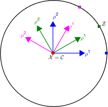
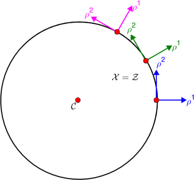
Figure 2: Different coordinate systems suitable to analyse and circular-core spiral wave. a) Center frame: the origin is taken at the center of the circular tip trajectory. b) Tip frame: the origin is taken at the current position of the spiral wave tip, and the ρ2superscript𝜌2{\color[rgb]{0,0,1}\rho}^{2} axis is tangent to the tip trajectory.

When going to a frame of reference rotating at ω=Kωs𝜔𝐾subscript𝜔𝑠{\color[rgb]{0,0,1}\omega}={\color[rgb]{0,0,1}K}{\color[rgb]{0,0,1}\omega_{s}}, (i.e. the spiral wave frequency), the solution becomes periodic:

𝐔(xa,t)=𝐮(ρA),tXA=cA,tΦ=ωformulae-sequence𝐔superscript𝑥𝑎𝑡subscript𝐮superscript𝜌𝐴formulae-sequencesubscript𝑡superscript𝑋𝐴superscript𝑐𝐴subscript𝑡Φ𝜔\begin{split}{\color[rgb]{0,0,1}\mathbf{U}}({\color[rgb]{0,0,1}x}^{\color[rgb]{0,0,1}a},{\color[rgb]{0,0,1}t})&={\color[rgb]{0,0,1}{\color[rgb]{0,0,1}\mathbf{u}}_{*}}({\color[rgb]{0,0,1}\rho}^{\color[rgb]{0,0,1}A}),\\ \partial_{\color[rgb]{0,0,1}t}{\color[rgb]{0,0,1}X}^{\color[rgb]{0,0,1}A}&={\color[rgb]{0,0,1}{\color[rgb]{0,0,1}c}^{{\color[rgb]{0,0,1}A}}},\\ \partial_{\color[rgb]{0,0,1}t}{\color[rgb]{0,0,1}\Phi}&={\color[rgb]{0,0,1}\omega}\end{split} (8)

with cAsuperscript𝑐𝐴{\color[rgb]{0,0,1}{\color[rgb]{0,0,1}c}^{{\color[rgb]{0,0,1}A}}} and ω𝜔{\color[rgb]{0,0,1}\omega} constant. We distinguish two frames of reference here:

IV.3.1 Center frame

The simplest coordinate system is found when taking its origin in the middle of the circular tip trajectory, as shown in Fig. 2(a), so that

cA=0.superscript𝑐𝐴0\displaystyle{\color[rgb]{0,0,1}{\color[rgb]{0,0,1}c}^{{\color[rgb]{0,0,1}A}}}=0.

This frame was used in the vast majority of previous works on spiral wave theory Keener (1988); Biktashev et al. (1994); Verschelde et al. (2007); Dierckx et al. (2009); Biktashev et al. (2010); Dierckx et al. (2012, 2013); Dierckx and Verschelde (2013); Li et al. (2014). This approach, however, is not optimal for describing the interaction of the spiral wave with localised heterogeneities, as dynamics is most influenced by stimuli close to the spiral wave tip rather than rotation centre, and the distance between the two can be significant.

IV.3.2 Tip frame

Therefore, we introduce another frame of reference, with the origin of coordinates ρAsuperscript𝜌𝐴{\color[rgb]{0,0,1}\rho}^{\color[rgb]{0,0,1}A} at the spiral wave tip, 𝒳=𝒵𝒳𝒵{\color[rgb]{0,0,1}\mathcal{X}}={\color[rgb]{0,0,1}\mathcal{Z}} as shown in Fig. 2b:

cA0.superscript𝑐𝐴0\displaystyle{\color[rgb]{0,0,1}{\color[rgb]{0,0,1}c}^{{\color[rgb]{0,0,1}A}}}\neq 0.

In this ‘tip frame’, the velocity of the spiral wave tip cAsuperscript𝑐𝐴{\color[rgb]{0,0,1}{\color[rgb]{0,0,1}c}^{{\color[rgb]{0,0,1}A}}} becomes constant. One can even choose the orientation of the frame such that c1=0superscript𝑐10{\color[rgb]{0,0,1}{\color[rgb]{0,0,1}c}^{1}}=0, c2=ωrsuperscript𝑐2𝜔𝑟{\color[rgb]{0,0,1}{\color[rgb]{0,0,1}c}^{2}}={\color[rgb]{0,0,1}\omega}{\color[rgb]{0,0,1}r} with r𝑟{\color[rgb]{0,0,1}r} the radius of the tip trajectory.

The tip frame closely relates to the kinematic approach of Zykov et al. Zykov (1987) and is particularly suited to describe large-core spiral waves.

Finally, note that the freedom in the choice of the definition of the tip may be exploited by taking uj=uj(𝒞)subscriptsuperscript𝑢𝑗subscript𝑢𝑗𝒞{{\color[rgb]{0,0,1}u^{*}_{{\color[rgb]{0,0,1}j}}}}={\color[rgb]{0,0,1}u}_{\color[rgb]{0,0,1}j}({\color[rgb]{0,0,1}\mathcal{C}}), uk=uk(𝒞)subscriptsuperscript𝑢𝑘subscript𝑢𝑘𝒞{{\color[rgb]{0,0,1}u^{*}_{{\color[rgb]{0,0,1}k}}}}={\color[rgb]{0,0,1}u}_{\color[rgb]{0,0,1}k}({\color[rgb]{0,0,1}\mathcal{C}}), so that 𝒵=𝒞𝒵𝒞{\color[rgb]{0,0,1}\mathcal{Z}}={\color[rgb]{0,0,1}\mathcal{C}}; then we have cA=0superscript𝑐𝐴0{\color[rgb]{0,0,1}{\color[rgb]{0,0,1}c}^{{\color[rgb]{0,0,1}A}}}=0 and recover the center frame as a special case.

IV.4 Meandering spiral waves

The case of biperiodic meander studied in this work is characterized by the fact that the spiral wave solution can be made time-periodic in a moving frame of reference. As in the case of periodically modulated waves, we introduce a temporal phase ΨΨ{\color[rgb]{0,0,1}\Psi}, which in the absence of perturbations increases from 00 to 2π2𝜋2\pi over the time interval T𝑇{\color[rgb]{0,0,1}T}: Ψ(t)=ΩtΨ𝑡Ω𝑡{\color[rgb]{0,0,1}\Psi}({\color[rgb]{0,0,1}t})={\color[rgb]{0,0,1}\Omega}{\color[rgb]{0,0,1}t}, Ω=2π/T>0Ω2𝜋𝑇0{\color[rgb]{0,0,1}\Omega}=2\pi/{\color[rgb]{0,0,1}T}>0. Without loss of generality, we may take Ψ(0)=0Ψ00\Psi(0)=0. In the context of spiral waves, we refer to ΨΨ{\color[rgb]{0,0,1}\Psi} as the meander phase, or temporal phase, as opposed to the rotation phase (angle) ΦΦ{\color[rgb]{0,0,1}\Phi}.

A meandering spiral solution is thus of the form:

𝐔(xa,t)𝐔superscript𝑥𝑎𝑡\displaystyle{\color[rgb]{0,0,1}\mathbf{U}}({\color[rgb]{0,0,1}x}^{\color[rgb]{0,0,1}a},{\color[rgb]{0,0,1}t}) =𝐮(ρA,Ψ(t)),absentsubscript𝐮superscript𝜌𝐴Ψ𝑡\displaystyle={\color[rgb]{0,0,1}{\color[rgb]{0,0,1}\mathbf{u}}_{*}}({\color[rgb]{0,0,1}\rho}^{\color[rgb]{0,0,1}A},{\color[rgb]{0,0,1}\Psi}({\color[rgb]{0,0,1}t})), (9a)
tXAsubscript𝑡superscript𝑋𝐴\displaystyle\partial_{\color[rgb]{0,0,1}t}{\color[rgb]{0,0,1}X}^{\color[rgb]{0,0,1}A} =cA(Ψ),absentsuperscript𝑐𝐴Ψ\displaystyle={\color[rgb]{0,0,1}{\color[rgb]{0,0,1}c}^{{\color[rgb]{0,0,1}A}}}({\color[rgb]{0,0,1}\Psi}), (9b)
tΦsubscript𝑡Φ\displaystyle\partial_{\color[rgb]{0,0,1}t}{\color[rgb]{0,0,1}\Phi} =ω(Ψ),absent𝜔Ψ\displaystyle={\color[rgb]{0,0,1}\omega}({\color[rgb]{0,0,1}\Psi}), (9c)
tΨsubscript𝑡Ψ\displaystyle\partial_{\color[rgb]{0,0,1}t}{\color[rgb]{0,0,1}\Psi} =Ω.absentΩ\displaystyle={\color[rgb]{0,0,1}\Omega}. (9d)

with 𝐮subscript𝐮{\color[rgb]{0,0,1}{\color[rgb]{0,0,1}\mathbf{u}}_{*}} 2π2𝜋2\pi-periodic in ΨΨ{\color[rgb]{0,0,1}\Psi}.

An overview of reference frames discussed below is given in Tab. 2.

The Euclidean transformation mapping 𝐮(x,y,t)𝐮𝑥𝑦𝑡{\color[rgb]{0,0,1}\mathbf{u}}({\color[rgb]{0,0,1}x},{\color[rgb]{0,0,1}y},{\color[rgb]{0,0,1}t}) to 𝐮(x,y,t+T)𝐮𝑥𝑦𝑡𝑇{\color[rgb]{0,0,1}\mathbf{u}}({\color[rgb]{0,0,1}x},{\color[rgb]{0,0,1}y},{\color[rgb]{0,0,1}t}+{\color[rgb]{0,0,1}T}) can, without loss of generality, be always thought of as either a pure rotation or a pure translation, since the composition of a rotation and a translation can always be written as a single rotation in 2D. Below we first treat the ‘pure rotation’ case, corresponding to non-resonant meander; the second case (pure translation), corresponding to resonant meander will be discussed in Sec. IV.5.

a) Refer to caption b) Refer to caption c) Refer to caption
d) Refer to caption e) Refer to caption f) Refer to caption

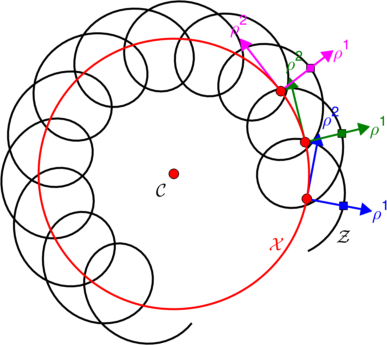
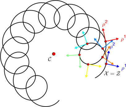
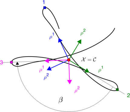
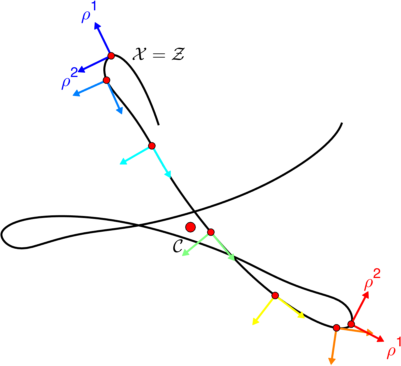
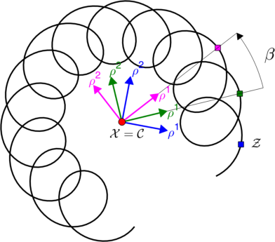
Figure 3: Different coordinate systems suitable to analyse and predict the motion of a meandering spiral wave. Panels a-d show cycloidal meander in Barkley’s model with parameters as in Fig. 1d; panels e-f illustrate linear-core meander in the FK-Guinea Pig cardiac model. Panels (a,e) show the ‘center frame’, where the origin is taken at the center of meander flower, with the frame rotating at the constant rate ω=β/T𝜔𝛽𝑇{\color[rgb]{0,0,1}\omega}={\color[rgb]{0,0,1}\beta}/{\color[rgb]{0,0,1}T}, where β𝛽{\color[rgb]{0,0,1}\beta} is the angle between consecutively visited petals. Panels (b,c) illustrate frames tailored describe the finite-core, which may either minimally rotate (over an angle β0subscript𝛽0{\color[rgb]{0,0,1}{\color[rgb]{0,0,1}\beta}_{0}} (see b) or co-rotate with the spiral, i.e.  rotate over βs=β0+2πKsubscript𝛽𝑠subscript𝛽02𝜋𝐾{\color[rgb]{0,0,1}{\color[rgb]{0,0,1}\beta}_{s}}={\color[rgb]{0,0,1}{\color[rgb]{0,0,1}\beta}_{0}}+2\pi{\color[rgb]{0,0,1}K} where K=±1𝐾plus-or-minus1{\color[rgb]{0,0,1}K}=\pm 1 labels chirality. Panels (d,f) show a tip frame of reference, with the origin 𝒳𝒳{\color[rgb]{0,0,1}\mathcal{X}} of the coordinate system at the current tip position and the ρ2superscript𝜌2{\color[rgb]{0,0,1}\rho}^{2}-axis tangent to the tip trajectory. The rotation rate of the tip frame is ω(Ψ)𝜔Ψ{\color[rgb]{0,0,1}\omega}({\color[rgb]{0,0,1}\Psi}), non-constant but periodic.

IV.4.1 Definition of the angle β𝛽{\color[rgb]{0,0,1}\beta} between petals

In the case of non-resonant meander, the spiral pattern repeats itself after time T𝑇{\color[rgb]{0,0,1}T}, but rotated around an angle β𝛽{\color[rgb]{0,0,1}\beta} around a point 𝒞𝒞{\color[rgb]{0,0,1}\mathcal{C}} that will become the center of the spiral tip trajectory (‘meander flower’); see Fig. 3.

Since we only impose that the solution be periodic, β𝛽{\color[rgb]{0,0,1}\beta} can be chosen up to an integer multiple of 2π2𝜋2\pi. Two values can play a special role, however. First, we can define this angle by following the movement of the spiral. If we attach a reference direction to the spiral wave tip (e.g. u1subscript𝑢1\vec{\nabla}{\color[rgb]{0,0,1}u}_{1} evaluated at the tip), this vector will turn over the angle βssubscript𝛽𝑠{\color[rgb]{0,0,1}{\color[rgb]{0,0,1}\beta}_{s}} during one spiral period, and for a faraway observer, the average spiral wave frequency (expressed as a positive number) will be ωs=Kβs/Tsubscript𝜔𝑠𝐾subscript𝛽𝑠𝑇{\color[rgb]{0,0,1}\omega_{s}}={\color[rgb]{0,0,1}K}{\color[rgb]{0,0,1}{\color[rgb]{0,0,1}\beta}_{s}}/{\color[rgb]{0,0,1}T}, where K=±1𝐾plus-or-minus1{\color[rgb]{0,0,1}K}=\pm 1 denotes chirality: K=1𝐾1{\color[rgb]{0,0,1}K}=1 for counterclockwise and K=1𝐾1{\color[rgb]{0,0,1}K}=-1 for clockwise rotation of both the spiral wave and the frame of reference.

Secondly, we may choose the β𝛽{\color[rgb]{0,0,1}\beta} as the element of the set βs+2πsubscript𝛽𝑠2𝜋{\color[rgb]{0,0,1}{\color[rgb]{0,0,1}\beta}_{s}}+2\pi\mathbb{Z} that has the minimal absolute value, and call this minimal value β0subscript𝛽0{\color[rgb]{0,0,1}{\color[rgb]{0,0,1}\beta}_{0}}. For the cases studied here, we find

βs=β0+2πKsubscript𝛽𝑠subscript𝛽02𝜋𝐾\displaystyle{\color[rgb]{0,0,1}{\color[rgb]{0,0,1}\beta}_{s}}={\color[rgb]{0,0,1}{\color[rgb]{0,0,1}\beta}_{0}}+2\pi{\color[rgb]{0,0,1}K}

with 0<|β0|<π0subscript𝛽0𝜋0<|{\color[rgb]{0,0,1}{\color[rgb]{0,0,1}\beta}_{0}}|<\pi.

IV.4.2 Center frame

We pick a frame rotating at constant frequency ω=β0/T𝜔subscript𝛽0𝑇{\color[rgb]{0,0,1}\omega}={\color[rgb]{0,0,1}{\color[rgb]{0,0,1}\beta}_{0}}/{\color[rgb]{0,0,1}T} around 𝒞𝒞{\color[rgb]{0,0,1}\mathcal{C}}, i.e. we take 𝒳=𝒞𝒳𝒞{\color[rgb]{0,0,1}\mathcal{X}}={\color[rgb]{0,0,1}\mathcal{C}}. In this ‘center frame of reference’, the meandering spiral solution becomes periodic. The solution is given by (9), with

cA=0,ω=β0/T.formulae-sequencesuperscript𝑐𝐴0𝜔subscript𝛽0𝑇\displaystyle{\color[rgb]{0,0,1}{\color[rgb]{0,0,1}c}^{{\color[rgb]{0,0,1}A}}}=0,\qquad{\color[rgb]{0,0,1}\omega}={\color[rgb]{0,0,1}{\color[rgb]{0,0,1}\beta}_{0}}/{\color[rgb]{0,0,1}T}.

This set of equations describes the spatial position the spiral wave in terms of the position of the center of the meander flower, and was used in Dierckx et al. (2017a). Since we chose 𝒳=𝒞𝒳𝒞{\color[rgb]{0,0,1}\mathcal{X}}={\color[rgb]{0,0,1}\mathcal{C}}, Eq. (9b) expresses that the center of the meander flower does not move in the absence of perturbations to the RDE (2).

It is also possible to relax the convention to take the period T𝑇{\color[rgb]{0,0,1}T} as the minimal time interval in which the solution is periodic modulo Euclidean group actions. E.g. when linear cores rotate over β180𝛽superscript180{\color[rgb]{0,0,1}\beta}\approx 180^{\circ} Fenton and Karma (1998), one could define the period to span two such cycles, bringing β0𝛽superscript0{\color[rgb]{0,0,1}\beta}\approx 0^{\circ} instead. This formalism can then be used to study phase-locking to constant external fields, generalising the results in Dierckx et al. (2017a).

Another theoretical possibility is to use the same setting as described by system (9), but with the choice β=βs𝛽subscript𝛽𝑠{\color[rgb]{0,0,1}\beta}={\color[rgb]{0,0,1}{\color[rgb]{0,0,1}\beta}_{s}} instead of β0subscript𝛽0{\color[rgb]{0,0,1}{\color[rgb]{0,0,1}\beta}_{0}}. This choice would ensure that the spiral wave solution, considered in the rotating frame, oscillates but not rotates and remains approximately stationary far from the centre. Neither of these two theoretical alternatives is used later in this paper, so we mention them only for completeness.

IV.4.3 Minimally rotating finite-core frame

It can be advantageous to allow the origin of the coordinate system to better follow the spiral wave tip. One possible choice is shown in Fig. 3b for reaction kinetics with cycloidal meander. We let the new origin move at constant angular velocity on a circular trajectory that approximates the exact tip trajectory, and refer to this situation as the ‘minimally rotating finite-core frame’:

τcA=0,ω=β0/T.formulae-sequencesubscript𝜏superscript𝑐𝐴0𝜔subscript𝛽0𝑇\displaystyle\partial_{\color[rgb]{0,0,1}\tau}{\color[rgb]{0,0,1}{\color[rgb]{0,0,1}c}^{{\color[rgb]{0,0,1}A}}}=0,\qquad{\color[rgb]{0,0,1}\omega}={\color[rgb]{0,0,1}{\color[rgb]{0,0,1}\beta}_{0}}/{\color[rgb]{0,0,1}T}.

IV.4.4 Co-rotating finite-core frame

We can let the minimally rotating finite core frame rotate around its axis, at a rate KΩ𝐾Ω{\color[rgb]{0,0,1}K}{\color[rgb]{0,0,1}\Omega}, to better follow the spiral wave rotation, bringing the absolute rotation rate to βssubscript𝛽𝑠{\color[rgb]{0,0,1}{\color[rgb]{0,0,1}\beta}_{s}}; see Fig. 3c. We will refer to this case as the ‘co-rotating finite-core frame’. It is again described by Eqs. (9), with

τcA=0,ω=βs/T.formulae-sequencesubscript𝜏superscript𝑐𝐴0𝜔subscript𝛽𝑠𝑇\displaystyle\partial_{\color[rgb]{0,0,1}\tau}{\color[rgb]{0,0,1}{\color[rgb]{0,0,1}c}^{{\color[rgb]{0,0,1}A}}}=0,\qquad{\color[rgb]{0,0,1}\omega}={\color[rgb]{0,0,1}{\color[rgb]{0,0,1}\beta}_{s}}/{\color[rgb]{0,0,1}T}. (10)

In this frame, the spiral solution 𝐮(ρA,Ψ)subscript𝐮superscript𝜌𝐴Ψ{\color[rgb]{0,0,1}{\color[rgb]{0,0,1}\mathbf{u}}_{*}}({\color[rgb]{0,0,1}\rho}^{\color[rgb]{0,0,1}A},{\color[rgb]{0,0,1}\Psi}) will not rotate if ΨΨ{\color[rgb]{0,0,1}\Psi} is increased from 00 to 2π2𝜋2\pi.

IV.4.5 Tip frame

Lastly, we let the origin 𝒳𝒳{\color[rgb]{0,0,1}\mathcal{X}} of the co-moving frame of reference coincide with the spiral wave tip position, i.e. 𝒳=𝒵𝒳𝒵{\color[rgb]{0,0,1}\mathcal{X}}={\color[rgb]{0,0,1}\mathcal{Z}}, Xa(t)Za(t)superscript𝑋𝑎𝑡superscript𝑍𝑎𝑡{\color[rgb]{0,0,1}{\color[rgb]{0,0,1}X}}^{a}({\color[rgb]{0,0,1}t})\equiv{\color[rgb]{0,0,1}Z}^{a}({\color[rgb]{0,0,1}t}); see Fig. 3c and f. Then cAsuperscript𝑐𝐴{\color[rgb]{0,0,1}{\color[rgb]{0,0,1}c}^{{\color[rgb]{0,0,1}A}}} and ω𝜔{\color[rgb]{0,0,1}\omega} become non-constant, 2π2𝜋2\pi-periodic functions of ΨΨ{\color[rgb]{0,0,1}\Psi}.

After one meander period of duration T𝑇{\color[rgb]{0,0,1}T}, the frame will have turned over an angle

βs=0Tω(Ψ(t))dt=1Ω02πω(Ψ)dΨ=ω¯T.subscript𝛽𝑠superscriptsubscript0𝑇𝜔Ψ𝑡differential-d𝑡1Ωsuperscriptsubscript02𝜋𝜔Ψdifferential-dΨ¯𝜔𝑇\displaystyle{\color[rgb]{0,0,1}{\color[rgb]{0,0,1}\beta}_{s}}=\int_{0}^{{\color[rgb]{0,0,1}T}}{\color[rgb]{0,0,1}\omega}({\color[rgb]{0,0,1}\Psi}({\color[rgb]{0,0,1}t}))\,\mathrm{d}{\color[rgb]{0,0,1}t}=\frac{1}{{\color[rgb]{0,0,1}\Omega}}\int_{0}^{2\pi}{\color[rgb]{0,0,1}\omega}({\color[rgb]{0,0,1}\Psi})\,\mathrm{d}{\color[rgb]{0,0,1}\Psi}=\bar{{\color[rgb]{0,0,1}\omega}}{\color[rgb]{0,0,1}T}.

If the tip trajectory is smooth, we can without loss of generality suppose that c1=0superscript𝑐10{\color[rgb]{0,0,1}{\color[rgb]{0,0,1}c}^{1}}=0, c2=c(Ψ)superscript𝑐2𝑐Ψ{\color[rgb]{0,0,1}{\color[rgb]{0,0,1}c}^{2}}={\color[rgb]{0,0,1}{\color[rgb]{0,0,1}c}}({\color[rgb]{0,0,1}\Psi}). This can always be achieved by exploiting the freedom in the definition of frame orientation angle ΦΦ{\color[rgb]{0,0,1}\Phi}.

IV.4.6 Comparison with the classical theory of meander

In the classical theory of rigidly rotating spiral waves, the critical eigenmodes for translation have eigenvalues ±iω1plus-or-minus𝑖subscript𝜔1\pm i{\color[rgb]{0,0,1}\omega}_{1}, where ω1subscript𝜔1{\color[rgb]{0,0,1}\omega}_{1} is the rotation frequency of the rigidly rotating spiral wave. If due to a parameter change in the medium, another complex eigenvalue pair crosses the imaginary axis at ±iω2plus-or-minus𝑖subscript𝜔2\pm i{\color[rgb]{0,0,1}\omega}_{2}, we have a Hopf bifurcation in the quotient system (rotating frame). If this bifurcation is supercritical, this results in an epicycloidal tip trajectory as shown in Fig. 3(a–c). In Barkley’s notation Barkley (1994), it is seen that beyond the Hopf bifurcation the absolute tip velocity will oscillate at ω2subscript𝜔2{\color[rgb]{0,0,1}\omega}_{2}. Hence, we conclude that Barkley’s ω2subscript𝜔2{\color[rgb]{0,0,1}\omega}_{2} equals ΩΩ{\color[rgb]{0,0,1}\Omega} used throughout this work. Secondly, in the circular-core regime just before the Hopf bifurcation, the spiral’s rotation frequency is ω1subscript𝜔1{\color[rgb]{0,0,1}\omega}_{1}, corresponding to ωssubscript𝜔𝑠{\color[rgb]{0,0,1}\omega_{s}} in our notation. We conclude that in the tip frame (where β=βs𝛽subscript𝛽𝑠{\color[rgb]{0,0,1}\beta}={\color[rgb]{0,0,1}{\color[rgb]{0,0,1}\beta}_{s}}), ω=ω1𝜔subscript𝜔1{\color[rgb]{0,0,1}\omega}={\color[rgb]{0,0,1}\omega}_{1} and in the minimally rotating frames, (where β=β0𝛽subscript𝛽0{\color[rgb]{0,0,1}\beta}={\color[rgb]{0,0,1}{\color[rgb]{0,0,1}\beta}_{0}}), ω=ω1KΩ𝜔subscript𝜔1𝐾Ω{\color[rgb]{0,0,1}\omega}={\color[rgb]{0,0,1}\omega}_{1}-{\color[rgb]{0,0,1}K}{\color[rgb]{0,0,1}\Omega}.

The case of resonant meander happens in the classical theory when ω2ω1subscript𝜔2subscript𝜔1{\color[rgb]{0,0,1}\omega}_{2}\rightarrow{\color[rgb]{0,0,1}\omega}_{1}. In our description, this happens when ω0𝜔0{\color[rgb]{0,0,1}\omega}\rightarrow 0 in the center or minimally co-rotating frame, or when ωΩ𝜔Ω{\color[rgb]{0,0,1}\omega}\rightarrow{\color[rgb]{0,0,1}\Omega} in the tip frame or fully co-rotating frame.

IV.5 Resonant meander

We now consider the case where the meandering spiral returns after the temporal period T𝑇{\color[rgb]{0,0,1}T} to the same state, but translated over a vector da=ca¯Tsuperscript𝑑𝑎¯superscript𝑐𝑎𝑇{\color[rgb]{0,0,1}d}^{\color[rgb]{0,0,1}a}=\overline{{\color[rgb]{0,0,1}{\color[rgb]{0,0,1}c}^{{\color[rgb]{0,0,1}a}}}}{\color[rgb]{0,0,1}T}; see Fig. 1(f). Different authors call this sort of solutions cycloidal motion Zykov (1986), 0superscript00^{\circ} isogon contours Winfree (1990), modulated travelling waves Barkley (1994); Wulff (1996b), resonant linear motion Golubitsky et al. (1997) or linear drift Ashwin et al. (2001). We shall refer to it here as resonant meander.

Note that during dynamics under external perturbations, the direction of spontaneous drift may change, such that a rotation phase needs to be introduced nevertheless. This makes this case distinct from the 1D modulated traveling wave from Par. III.4.

The solution is still given by (9), with cAsuperscript𝑐𝐴{\color[rgb]{0,0,1}{\color[rgb]{0,0,1}c}^{{\color[rgb]{0,0,1}A}}} and ω𝜔{\color[rgb]{0,0,1}\omega} depending on the chosen reference frame:

IV.5.1 Minimally rotating co-moving frame

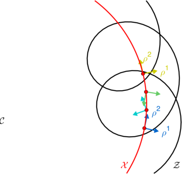
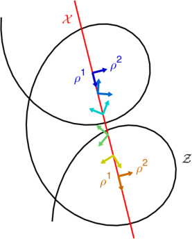
First, we let the origin of our coordinate system move on a straight line with velocity c1,c2superscript𝑐1superscript𝑐2{\color[rgb]{0,0,1}{\color[rgb]{0,0,1}c}^{1}},{\color[rgb]{0,0,1}{\color[rgb]{0,0,1}c}^{2}}, without frame rotation, parallel to the line along which the resonant spiral travels over time. This situation is sketched in Fig. 4a. Then, we find:

τcA=0,τΦ=0.formulae-sequencesubscript𝜏superscript𝑐𝐴0subscript𝜏Φ0\displaystyle\partial_{\color[rgb]{0,0,1}\tau}{\color[rgb]{0,0,1}{\color[rgb]{0,0,1}c}^{{\color[rgb]{0,0,1}A}}}=0,\qquad\partial_{\color[rgb]{0,0,1}\tau}{\color[rgb]{0,0,1}\Phi}=0.

Since the frame is not rotating, the function 𝐮(ρA,Ψ)subscript𝐮superscript𝜌𝐴Ψ{\color[rgb]{0,0,1}{\color[rgb]{0,0,1}\mathbf{u}}_{*}}({\color[rgb]{0,0,1}\rho}^{\color[rgb]{0,0,1}A},{\color[rgb]{0,0,1}\Psi}) shows a spiral that rotates a full turn when ΨΨ{\color[rgb]{0,0,1}\Psi} is raised from 00 to 2π2𝜋2\pi.

IV.5.2 Co-rotating, co-moving frame

We can also let the previous frame rotate at ω=KΩ𝜔𝐾Ω{\color[rgb]{0,0,1}\omega}={\color[rgb]{0,0,1}K}{\color[rgb]{0,0,1}\Omega}, while its origin moves on a straight line at constant speed parallel to the displacement direction of the resonant spiral. We again obtain Eqs. (9), with

cA=RAa(Φ)ca,τΦ=KΩ.formulae-sequencesuperscript𝑐𝐴subscriptsuperscript𝑅𝐴𝑎Φsuperscript𝑐𝑎subscript𝜏Φ𝐾Ω\displaystyle{\color[rgb]{0,0,1}{\color[rgb]{0,0,1}c}^{{\color[rgb]{0,0,1}A}}}={\color[rgb]{0,0,1}{R^{{\color[rgb]{0,0,1}A}}}_{{\color[rgb]{0,0,1}a}}}({\color[rgb]{0,0,1}\Phi}){\color[rgb]{0,0,1}{\color[rgb]{0,0,1}c}^{{\color[rgb]{0,0,1}a}}},\qquad\partial_{\color[rgb]{0,0,1}\tau}{\color[rgb]{0,0,1}\Phi}={\color[rgb]{0,0,1}K}{\color[rgb]{0,0,1}\Omega}.

and casuperscript𝑐𝑎{\color[rgb]{0,0,1}{\color[rgb]{0,0,1}c}^{{\color[rgb]{0,0,1}a}}} constant. The spiral wave profile 𝐮(ρA,0,Ψ)subscript𝐮superscript𝜌𝐴0Ψ{\color[rgb]{0,0,1}{\color[rgb]{0,0,1}\mathbf{u}}_{*}}({\color[rgb]{0,0,1}\rho}^{\color[rgb]{0,0,1}A},0,{\color[rgb]{0,0,1}\Psi}) does not rotate a full turn when ΨΨ{\color[rgb]{0,0,1}\Psi} is raised from 00 to 2π2𝜋2\pi; it only deforms (‘breathes’), see e.g. Foulkes and Biktashev (2010).

IV.5.3 Tip frame

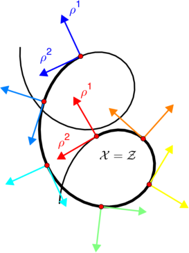
As in the non-resonant case, it is also possible to find a tip-based frame of reference:

Φ=ϑ,Xa=Zaformulae-sequenceΦitalic-ϑsuperscript𝑋𝑎superscript𝑍𝑎\displaystyle{\color[rgb]{0,0,1}\Phi}={\color[rgb]{0,0,1}\vartheta},\qquad{\color[rgb]{0,0,1}{\color[rgb]{0,0,1}X}}^{\color[rgb]{0,0,1}a}={\color[rgb]{0,0,1}Z}^{\color[rgb]{0,0,1}a}

Note that during the time interval T𝑇{\color[rgb]{0,0,1}T}, the angle ΦΦ{\color[rgb]{0,0,1}\Phi} needs to turn over ±2πplus-or-minus2𝜋\pm 2\pi, whence

ω¯=KΩ.¯𝜔𝐾Ω\displaystyle\overline{{\color[rgb]{0,0,1}\omega}}={\color[rgb]{0,0,1}K}{\color[rgb]{0,0,1}\Omega}.

Here, one can see that resonant meander is indeed a special case of Eqs. (9), in which the average value of ω𝜔{{\color[rgb]{0,0,1}\omega}} tends to KΩ𝐾Ω{\color[rgb]{0,0,1}K}{\color[rgb]{0,0,1}\Omega}. In the tip frame, 𝐮subscript𝐮{\color[rgb]{0,0,1}{\color[rgb]{0,0,1}\mathbf{u}}_{*}} represents a spiral that performs no net rotation when ΨΨ{\color[rgb]{0,0,1}\Psi} is raised from 00 to 2π2𝜋2\pi, it merely deforms around the same orientation.

a) Refer to caption b) Refer to caption
c) Refer to caption

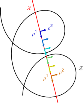
Figure 4: Reference frames for resonant meander. a) The ‘minimally rotating co-moving frame’ is rigidly translating such that the solution becomes periodic. During one period (i.e. between the frames shown), the frame rotates over an angle 2πK2𝜋𝐾2\pi{\color[rgb]{0,0,1}K}. b) The ‘co-rotating co-moving frame’ is obtained from the average frame by letting the moving coordinates rotate at constant frequency KΩ=2πK/T𝐾Ω2𝜋𝐾𝑇{\color[rgb]{0,0,1}K}{\color[rgb]{0,0,1}\Omega}=2\pi{\color[rgb]{0,0,1}K}/{\color[rgb]{0,0,1}T}. c) Tip-based frame of reference, with the origin of the coordinate system at the current tip position and the ρ2superscript𝜌2{\color[rgb]{0,0,1}\rho}^{2}-axis tangent to the tip trajectory. Rotation rate of the frame is ω(t)𝜔𝑡{\color[rgb]{0,0,1}\omega}({\color[rgb]{0,0,1}t}), non-constant but periodic.

IV.6 General case

The foregoing patterns can all be captured by noting that each broken continuous symmetry delivers a collective coordinate XMsuperscript𝑋𝑀{\color[rgb]{0,0,1}X}^{\color[rgb]{0,0,1}M}:

xX1,yX2,θΦ,tΨ.formulae-sequence𝑥superscript𝑋1formulae-sequence𝑦superscript𝑋2formulae-sequence𝜃Φ𝑡Ψ\displaystyle{\color[rgb]{0,0,1}x}\rightarrow{\color[rgb]{0,0,1}X}^{1},\qquad{\color[rgb]{0,0,1}y}\rightarrow{\color[rgb]{0,0,1}X}^{2},\qquad{\color[rgb]{0,0,1}\theta}\rightarrow{\color[rgb]{0,0,1}\Phi},\qquad{\color[rgb]{0,0,1}t}\rightarrow{\color[rgb]{0,0,1}\Psi}.

We shall denote this as xMXMsuperscript𝑥𝑀superscript𝑋𝑀{\color[rgb]{0,0,1}x}^{\color[rgb]{0,0,1}M}\rightarrow{\color[rgb]{0,0,1}X}^{\color[rgb]{0,0,1}M}; there is one pair for every broken continuous symmetry. We also convene that

{XM}superscript𝑋𝑀\displaystyle\{{\color[rgb]{0,0,1}X}^{\color[rgb]{0,0,1}M}\} ={XA,Φ,Ψ},absentsuperscript𝑋𝐴ΦΨ\displaystyle=\{{\color[rgb]{0,0,1}X}^{\color[rgb]{0,0,1}A},{\color[rgb]{0,0,1}\Phi},{\color[rgb]{0,0,1}\Psi}\},
{Xm}superscript𝑋𝑚\displaystyle\{{\color[rgb]{0,0,1}X}^{\color[rgb]{0,0,1}m}\} ={Xa,Φ,Ψ}.absentsuperscript𝑋𝑎ΦΨ\displaystyle=\{{\color[rgb]{0,0,1}X}^{\color[rgb]{0,0,1}a},{\color[rgb]{0,0,1}\Phi},{\color[rgb]{0,0,1}\Psi}\}.

The use of indices M𝑀{\color[rgb]{0,0,1}M} vs. m𝑚{\color[rgb]{0,0,1}m} thus distinguishes between the moving and lab frames of reference, as did A𝐴{\color[rgb]{0,0,1}A} vs. a𝑎{\color[rgb]{0,0,1}a} for the translational modes only. Note that Xasuperscript𝑋𝑎{\color[rgb]{0,0,1}X}^{\color[rgb]{0,0,1}a} is tip position in the lab frame, while xasuperscript𝑥𝑎{\color[rgb]{0,0,1}x}^{\color[rgb]{0,0,1}a} is a lab frame Cartesian coordinate that can label any point.

The parameters of the solution xMsuperscript𝑥𝑀{\color[rgb]{0,0,1}x}^{\color[rgb]{0,0,1}M} are chosen from {x,y,θ,t}𝑥𝑦𝜃𝑡\{{\color[rgb]{0,0,1}x},{\color[rgb]{0,0,1}y},{\color[rgb]{0,0,1}\theta},{\color[rgb]{0,0,1}t}\} and XMsuperscript𝑋𝑀{\color[rgb]{0,0,1}X}^{\color[rgb]{0,0,1}M} are the collective coordinates. Then we find that all aforementioned sets of equations (6), (7), (8), and (9) that capture the evolution of particular reaction-diffusion patterns can be written as

𝐔(xa,t)=𝐮(ρA,Ψ),tXM=cM(Ψ)formulae-sequence𝐔superscript𝑥𝑎𝑡subscript𝐮superscript𝜌𝐴Ψsubscript𝑡superscript𝑋𝑀superscript𝑐𝑀Ψ\begin{split}{\color[rgb]{0,0,1}\mathbf{U}}({\color[rgb]{0,0,1}x}^{\color[rgb]{0,0,1}a},{\color[rgb]{0,0,1}t})&={\color[rgb]{0,0,1}{\color[rgb]{0,0,1}\mathbf{u}}_{*}}({\color[rgb]{0,0,1}\rho}^{\color[rgb]{0,0,1}A},{\color[rgb]{0,0,1}\Psi}),\\ \partial_{\color[rgb]{0,0,1}t}{\color[rgb]{0,0,1}X}^{\color[rgb]{0,0,1}M}&={\color[rgb]{0,0,1}{\color[rgb]{0,0,1}c}^{{\color[rgb]{0,0,1}M}}}({\color[rgb]{0,0,1}\Psi})\end{split} (11)

given a time-dependent spatial coordinate transformation

ρA(xa,t)superscript𝜌𝐴superscript𝑥𝑎𝑡\displaystyle{\color[rgb]{0,0,1}\rho}^{\color[rgb]{0,0,1}A}({\color[rgb]{0,0,1}x}^{\color[rgb]{0,0,1}a},{\color[rgb]{0,0,1}t}) =g(xa,XM(t))absent𝑔superscript𝑥𝑎superscript𝑋𝑀𝑡\displaystyle={\color[rgb]{0,0,1}g}({\color[rgb]{0,0,1}x}^{\color[rgb]{0,0,1}a},{\color[rgb]{0,0,1}X}^{\color[rgb]{0,0,1}M}({\color[rgb]{0,0,1}t}))

that has as many degrees of freedom as broken Galilean symmetries by the solution.

Note that the representation (11) is not unique. E.g. for a rigidly rotating spiral wave, one could choose 𝐔(xa,t)=𝐮(ρA,Ψ)𝐔superscript𝑥𝑎𝑡subscript𝐮superscript𝜌𝐴Ψ{\color[rgb]{0,0,1}\mathbf{U}}({\color[rgb]{0,0,1}x}^{\color[rgb]{0,0,1}a},{\color[rgb]{0,0,1}t})={\color[rgb]{0,0,1}{\color[rgb]{0,0,1}\mathbf{u}}_{*}}({\color[rgb]{0,0,1}\rho}^{\color[rgb]{0,0,1}A},{\color[rgb]{0,0,1}\Psi}) that is periodic in its third argument ΨϑΨitalic-ϑ{\color[rgb]{0,0,1}\Psi}\equiv{\color[rgb]{0,0,1}\vartheta} and ρAsuperscript𝜌𝐴{\color[rgb]{0,0,1}\rho}^{\color[rgb]{0,0,1}A} identical to the lab frame coordinates xasuperscript𝑥𝑎{\color[rgb]{0,0,1}x}^{\color[rgb]{0,0,1}a}. However, one can also choose to let 𝐮subscript𝐮{\color[rgb]{0,0,1}{\color[rgb]{0,0,1}\mathbf{u}}_{*}} in the right-hand side of Eq. (11) only depend on ρAsuperscript𝜌𝐴{\color[rgb]{0,0,1}\rho}^{\color[rgb]{0,0,1}A} and ΨΨ{\color[rgb]{0,0,1}\Psi}.

For the actual calculations performed below, we work with Eqs. (9) for a meandering spiral in a tip-based frame of reference, since they contain all other patterns and reference frames as a special case, i.e. Eqs. (6), (7), (8)and (9). Those can be recovered from Eq. (9) by considering 𝐮subscript𝐮{\color[rgb]{0,0,1}{\color[rgb]{0,0,1}\mathbf{u}}_{*}} independent of a collective coordinate. Thereafter, the evolution equation for that coordinate becomes irrelevant and can be dropped. E.g. the theory of rigidly rotating spirals follows from the meander case by taking 𝐮subscript𝐮{\color[rgb]{0,0,1}{\color[rgb]{0,0,1}\mathbf{u}}_{*}} independent of ΨΨ{\color[rgb]{0,0,1}\Psi} and leaving out the evolution equation for ΨΨ{\color[rgb]{0,0,1}\Psi}. From this case, the 1D traveling wave case follows by considering 𝐮subscript𝐮{\color[rgb]{0,0,1}{\color[rgb]{0,0,1}\mathbf{u}}_{*}} to be also independent of ΦΦ{\color[rgb]{0,0,1}\Phi} and ρ2superscript𝜌2{\color[rgb]{0,0,1}\rho}^{2}, such that Eq. (6) follows.

V Properties of the linearized problem

V.1 Right-hand zero modes

Since the original RD Eq. (2) is invariant under spatial, rotational and temporal shifts, one has that, when a solution is rotated, or shifted in space or time, it is still a solution to Eq. (2). This can be made explicit by substituting 𝐮(x+ε~,y,t)𝐮𝑥~𝜀𝑦𝑡{\color[rgb]{0,0,1}\mathbf{u}}({\color[rgb]{0,0,1}x}+{\color[rgb]{0,0,1}\tilde{\varepsilon}},{\color[rgb]{0,0,1}y},{\color[rgb]{0,0,1}t}) in Eq. (2), and similar for other coordinates, yielding in first order in ε~~𝜀{\color[rgb]{0,0,1}\tilde{\varepsilon}} that

^𝐔xM=𝟎.^𝐔superscript𝑥𝑀0\displaystyle{\color[rgb]{0,0,1}\hat{\ell}}\ \frac{\partial{\color[rgb]{0,0,1}\mathbf{U}}}{\partial{\color[rgb]{0,0,1}x}^{\color[rgb]{0,0,1}M}}=\boldsymbol{0}. (12)

where

^=𝐏(x2+y2)+𝐅(𝐔)t.^𝐏superscriptsubscript𝑥2superscriptsubscript𝑦2superscript𝐅𝐔subscript𝑡\displaystyle{\color[rgb]{0,0,1}\hat{\ell}}={\color[rgb]{0,0,1}{\mathbf{P}}}(\partial_{\color[rgb]{0,0,1}x}^{2}+\partial_{\color[rgb]{0,0,1}y}^{2})+{\color[rgb]{0,0,1}\mathbf{F}}^{\prime}({\color[rgb]{0,0,1}\mathbf{U}})-\partial_{\color[rgb]{0,0,1}t}. (13)

As expected, shifted values of the solution are right-hand zero modes of the linearized operator ^^{\color[rgb]{0,0,1}\hat{\ell}} associated to the RDE, in the lab frame.

In several previous works, a moving frame was chosen in which the solution was either stationary Keener (1986); Biktashev et al. (1994); Verschelde et al. (2007); Dierckx et al. (2009, 2012) or periodic Dierckx et al. (2017a). This comes down to expressing the derivative in Eq. (12) in the moving frame using the chain rule. From Eqs. (9) then follows

t𝐔=A𝐮tρA+Ψ𝐮tΨ=A𝐮[ωRAa(Φ)ϵab(xbXb(t))RAa(Φ)ca]=ΩΨ𝐮ωθ𝐮cAA𝐮.subscript𝑡𝐔subscript𝐴subscript𝐮subscript𝑡superscript𝜌𝐴subscriptΨsubscript𝐮subscript𝑡Ψsubscript𝐴subscript𝐮delimited-[]𝜔subscriptsuperscript𝑅𝐴𝑎Φsubscriptsuperscriptitalic-ϵ𝑎𝑏superscript𝑥𝑏superscript𝑋𝑏𝑡subscriptsuperscript𝑅𝐴𝑎Φsuperscript𝑐𝑎ΩsubscriptΨsubscript𝐮𝜔subscript𝜃subscript𝐮superscript𝑐𝐴subscript𝐴subscript𝐮\begin{split}\partial_{\color[rgb]{0,0,1}t}{\color[rgb]{0,0,1}\mathbf{U}}&=\partial_{\color[rgb]{0,0,1}A}{\color[rgb]{0,0,1}{\color[rgb]{0,0,1}\mathbf{u}}_{*}}\partial_{\color[rgb]{0,0,1}t}{\color[rgb]{0,0,1}\rho}^{\color[rgb]{0,0,1}A}+\partial_{\color[rgb]{0,0,1}\Psi}{\color[rgb]{0,0,1}{\color[rgb]{0,0,1}\mathbf{u}}_{*}}\partial_{\color[rgb]{0,0,1}t}{\color[rgb]{0,0,1}\Psi}\\ &=\partial_{\color[rgb]{0,0,1}A}{\color[rgb]{0,0,1}{\color[rgb]{0,0,1}\mathbf{u}}_{*}}[{\color[rgb]{0,0,1}\omega}{\color[rgb]{0,0,1}{R^{{\color[rgb]{0,0,1}A}}}_{{\color[rgb]{0,0,1}a}}}({\color[rgb]{0,0,1}\Phi}){\color[rgb]{0,0,1}{{\color[rgb]{0,0,1}\epsilon}^{{\color[rgb]{0,0,1}a}}}_{{\color[rgb]{0,0,1}b}}}({\color[rgb]{0,0,1}x}^{\color[rgb]{0,0,1}b}-{\color[rgb]{0,0,1}X}^{\color[rgb]{0,0,1}b}({\color[rgb]{0,0,1}t}))-{\color[rgb]{0,0,1}{R^{{\color[rgb]{0,0,1}A}}}_{{\color[rgb]{0,0,1}a}}}({\color[rgb]{0,0,1}\Phi}){\color[rgb]{0,0,1}{\color[rgb]{0,0,1}c}^{{\color[rgb]{0,0,1}a}}}]\\ &={\color[rgb]{0,0,1}\Omega}\partial_{\color[rgb]{0,0,1}\Psi}{\color[rgb]{0,0,1}{\color[rgb]{0,0,1}\mathbf{u}}_{*}}-{\color[rgb]{0,0,1}\omega}\partial_{\color[rgb]{0,0,1}\theta}{\color[rgb]{0,0,1}{\color[rgb]{0,0,1}\mathbf{u}}_{*}}-{\color[rgb]{0,0,1}{\color[rgb]{0,0,1}c}^{{\color[rgb]{0,0,1}A}}}\partial_{\color[rgb]{0,0,1}A}{\color[rgb]{0,0,1}{\color[rgb]{0,0,1}\mathbf{u}}_{*}}.\end{split} (14)

Here, θ𝜃{\color[rgb]{0,0,1}\theta} is the polar angle around the origin of the chosen moving reference frame. Thus, 𝐮subscript𝐮{\color[rgb]{0,0,1}{\color[rgb]{0,0,1}\mathbf{u}}_{*}} obeys

𝐏Δ𝐮+𝐅(𝐮)+ωθ𝐮+cAA𝐮ΩΨ𝐮=𝟎.𝐏Δsubscript𝐮𝐅subscript𝐮𝜔subscript𝜃subscript𝐮superscript𝑐𝐴subscript𝐴subscript𝐮ΩsubscriptΨsubscript𝐮0\displaystyle{\color[rgb]{0,0,1}{\mathbf{P}}}\Delta{\color[rgb]{0,0,1}{\color[rgb]{0,0,1}\mathbf{u}}_{*}}+{\color[rgb]{0,0,1}\mathbf{F}}({\color[rgb]{0,0,1}{\color[rgb]{0,0,1}\mathbf{u}}_{*}})+{\color[rgb]{0,0,1}\omega}\partial_{\color[rgb]{0,0,1}\theta}{\color[rgb]{0,0,1}{\color[rgb]{0,0,1}\mathbf{u}}_{*}}+{\color[rgb]{0,0,1}{\color[rgb]{0,0,1}c}^{{\color[rgb]{0,0,1}A}}}\partial_{\color[rgb]{0,0,1}A}{\color[rgb]{0,0,1}{\color[rgb]{0,0,1}\mathbf{u}}_{*}}-{\color[rgb]{0,0,1}\Omega}\partial_{\color[rgb]{0,0,1}\Psi}{\color[rgb]{0,0,1}{\color[rgb]{0,0,1}\mathbf{u}}_{*}}=\mathbf{0}. (15)

Here, ω𝜔{\color[rgb]{0,0,1}\omega} and cAsuperscript𝑐𝐴{\color[rgb]{0,0,1}{\color[rgb]{0,0,1}c}^{{\color[rgb]{0,0,1}A}}} may depend on ΨΨ{\color[rgb]{0,0,1}\Psi} (which is the case in the tip frame of a meandering spiral wave). The linear operator associated to Eq. (15) is

𝓛^=𝐏Δ+𝐅(𝐮)+ωθ+cAAΩΨ^𝓛𝐏Δsuperscript𝐅subscript𝐮𝜔subscript𝜃superscript𝑐𝐴subscript𝐴ΩsubscriptΨ\displaystyle{\color[rgb]{0,0,1}\hat{\boldsymbol{\mathcal{L}}}}={\color[rgb]{0,0,1}{\mathbf{P}}}\Delta+{\color[rgb]{0,0,1}\mathbf{F}}^{\prime}({\color[rgb]{0,0,1}{\color[rgb]{0,0,1}\mathbf{u}}_{*}})+{\color[rgb]{0,0,1}\omega}\partial_{\color[rgb]{0,0,1}\theta}+{\color[rgb]{0,0,1}{\color[rgb]{0,0,1}c}^{{\color[rgb]{0,0,1}A}}}\partial_{\color[rgb]{0,0,1}A}-{\color[rgb]{0,0,1}\Omega}\partial_{\color[rgb]{0,0,1}\Psi}

Since the original RDE (2) is invariant in space, one has that in an infinite medium, if 𝐔(xa,t)𝐔superscript𝑥𝑎𝑡{\color[rgb]{0,0,1}\mathbf{U}}({\color[rgb]{0,0,1}x}^{\color[rgb]{0,0,1}a},{\color[rgb]{0,0,1}t}) is a solution, so should 𝐔(xa+ε~a,t)𝐔superscript𝑥𝑎superscript~𝜀𝑎𝑡{\color[rgb]{0,0,1}\mathbf{U}}({\color[rgb]{0,0,1}x}^{\color[rgb]{0,0,1}a}+{\color[rgb]{0,0,1}\tilde{\varepsilon}}^{\color[rgb]{0,0,1}a},{\color[rgb]{0,0,1}t}) for any constant displacement ε~asuperscript~𝜀𝑎{\color[rgb]{0,0,1}\tilde{\varepsilon}}^{\color[rgb]{0,0,1}a}. We find in one spatial dimension that

𝓛^ρ𝐮=𝟎.^𝓛subscript𝜌subscript𝐮0\displaystyle{\color[rgb]{0,0,1}\hat{\boldsymbol{\mathcal{L}}}}\partial_{{\color[rgb]{0,0,1}\rho}}{\color[rgb]{0,0,1}{\color[rgb]{0,0,1}\mathbf{u}}_{*}}=\boldsymbol{0}.

In two spatial dimensions, we remark that a𝐔=A𝐮RAa(Φ)subscript𝑎𝐔subscript𝐴subscript𝐮subscriptsuperscript𝑅𝐴𝑎Φ\partial_{\color[rgb]{0,0,1}a}{\color[rgb]{0,0,1}\mathbf{U}}=\partial_{\color[rgb]{0,0,1}A}{\color[rgb]{0,0,1}{\color[rgb]{0,0,1}\mathbf{u}}_{*}}\,{\color[rgb]{0,0,1}{R^{{\color[rgb]{0,0,1}A}}}_{{\color[rgb]{0,0,1}a}}}({\color[rgb]{0,0,1}\Phi}), such that we find in first order in ε~asuperscript~𝜀𝑎{\color[rgb]{0,0,1}\tilde{\varepsilon}}^{\color[rgb]{0,0,1}a}:

𝓛^A𝐮=ωϵABB𝐮.^𝓛subscript𝐴subscript𝐮𝜔superscriptsubscriptitalic-ϵ𝐴𝐵subscript𝐵subscript𝐮\displaystyle{\color[rgb]{0,0,1}\hat{\boldsymbol{\mathcal{L}}}}\partial_{\color[rgb]{0,0,1}A}{\color[rgb]{0,0,1}{\color[rgb]{0,0,1}\mathbf{u}}_{*}}={\color[rgb]{0,0,1}\omega}{\color[rgb]{0,0,1}{{\color[rgb]{0,0,1}\epsilon}_{{\color[rgb]{0,0,1}A}}}^{{\color[rgb]{0,0,1}B}}}\partial_{\color[rgb]{0,0,1}B}{\color[rgb]{0,0,1}{\color[rgb]{0,0,1}\mathbf{u}}_{*}}. (16)

By taking complex combinations 𝐕±=(1/2)(x𝐮±iy𝐮)subscript𝐕plus-or-minus12plus-or-minussubscript𝑥subscript𝐮𝑖subscript𝑦subscript𝐮{\color[rgb]{0,0,1}\mathbf{V}}_{\pm}=-(1/2)(\partial_{\color[rgb]{0,0,1}x}{\color[rgb]{0,0,1}{\color[rgb]{0,0,1}\mathbf{u}}_{*}}\pm i\partial_{\color[rgb]{0,0,1}y}{\color[rgb]{0,0,1}{\color[rgb]{0,0,1}\mathbf{u}}_{*}}), one obtains true eigenmodes of 𝓛^^𝓛{\color[rgb]{0,0,1}\hat{\boldsymbol{\mathcal{L}}}}, as 𝓛^𝐕±=±iω𝐕±^𝓛subscript𝐕plus-or-minusplus-or-minus𝑖𝜔subscript𝐕plus-or-minus{\color[rgb]{0,0,1}\hat{\boldsymbol{\mathcal{L}}}}{\color[rgb]{0,0,1}\mathbf{V}}_{\pm}=\pm i{\color[rgb]{0,0,1}\omega}{\color[rgb]{0,0,1}\mathbf{V}}_{\pm} Biktasheva et al. (2009). Note that in some of the chosen reference frames, ω𝜔{\color[rgb]{0,0,1}\omega} may depend on ΨΨ{\color[rgb]{0,0,1}\Psi}, and the ‘eigenmodes’ of the system are 2π2𝜋2\pi-periodic functions of ΨΨ{\color[rgb]{0,0,1}\Psi}.

For 2D patterns, we can state that a solution that is rotated around an angle ε~~𝜀{\color[rgb]{0,0,1}\tilde{\varepsilon}} around the current origin (i.e. spiral tip position or meander centre position) will still be a solution. With θ=ϵABρABsubscript𝜃superscriptsubscriptitalic-ϵ𝐴𝐵superscript𝜌𝐴subscript𝐵\partial_{\color[rgb]{0,0,1}\theta}={\color[rgb]{0,0,1}{{\color[rgb]{0,0,1}\epsilon}_{{\color[rgb]{0,0,1}A}}}^{{\color[rgb]{0,0,1}B}}}{\color[rgb]{0,0,1}\rho}^{\color[rgb]{0,0,1}A}\partial_{\color[rgb]{0,0,1}B}, one finds that, if 𝐔(xa,t)+ε~θ𝐔(xa,t)𝐔superscript𝑥𝑎𝑡~𝜀subscript𝜃𝐔superscript𝑥𝑎𝑡{\color[rgb]{0,0,1}\mathbf{U}}({\color[rgb]{0,0,1}x}^{\color[rgb]{0,0,1}a},{\color[rgb]{0,0,1}t})+{\color[rgb]{0,0,1}\tilde{\varepsilon}}\partial_{\color[rgb]{0,0,1}\theta}{\color[rgb]{0,0,1}\mathbf{U}}({\color[rgb]{0,0,1}x}^{\color[rgb]{0,0,1}a},{\color[rgb]{0,0,1}t}) is a solution, then

𝓛^θ𝐮=𝟎.^𝓛subscript𝜃subscript𝐮0\displaystyle{\color[rgb]{0,0,1}\hat{\boldsymbol{\mathcal{L}}}}\partial_{\color[rgb]{0,0,1}\theta}{\color[rgb]{0,0,1}{\color[rgb]{0,0,1}\mathbf{u}}_{*}}=\boldsymbol{0}.

We will denote θ𝐮subscript𝜃subscript𝐮-\partial_{\color[rgb]{0,0,1}\theta}{\color[rgb]{0,0,1}{\color[rgb]{0,0,1}\mathbf{u}}_{*}} as 𝐕Φsubscript𝐕Φ{\color[rgb]{0,0,1}\mathbf{V}}_{\color[rgb]{0,0,1}\Phi} and A𝐮subscript𝐴subscript𝐮-\partial_{\color[rgb]{0,0,1}A}{\color[rgb]{0,0,1}{\color[rgb]{0,0,1}\mathbf{u}}_{*}} as 𝐕Asubscript𝐕𝐴{\color[rgb]{0,0,1}\mathbf{V}}_{\color[rgb]{0,0,1}A}.

Thirdly, expressing that a time-shifted solution 𝐔(xa,t+ε~)𝐔superscript𝑥𝑎𝑡~𝜀{\color[rgb]{0,0,1}\mathbf{U}}({\color[rgb]{0,0,1}x}^{\color[rgb]{0,0,1}a},{\color[rgb]{0,0,1}t}+{\color[rgb]{0,0,1}\tilde{\varepsilon}}) also solves (2) yields

𝓛^t𝐮=𝟎.^𝓛subscript𝑡subscript𝐮0\displaystyle{\color[rgb]{0,0,1}\hat{\boldsymbol{\mathcal{L}}}}\partial_{\color[rgb]{0,0,1}t}{\color[rgb]{0,0,1}{\color[rgb]{0,0,1}\mathbf{u}}_{*}}=\mathbf{0}.

where t𝐮subscript𝑡subscript𝐮\partial_{\color[rgb]{0,0,1}t}{\color[rgb]{0,0,1}{\color[rgb]{0,0,1}\mathbf{u}}_{*}}, also denoted 𝐕Ψsubscript𝐕Ψ{\color[rgb]{0,0,1}\mathbf{V}}_{\color[rgb]{0,0,1}\Psi}, is given by Eq. (14).

In the case of meandering spirals, 𝐕Φsubscript𝐕Φ{\color[rgb]{0,0,1}\mathbf{V}}_{\color[rgb]{0,0,1}\Phi} is linearly independent of 𝐕Ψsubscript𝐕Ψ{\color[rgb]{0,0,1}\mathbf{V}}_{\color[rgb]{0,0,1}\Psi}, since otherwise a shift in time would be equivalent to simple rotation, and we would find ourselves in the non-meandering case.

To summarise, equation (13) defines the set of NBSsubscript𝑁𝐵𝑆{\color[rgb]{0,0,1}N_{BS}} zero modes for the linearized operator ^^{\color[rgb]{0,0,1}\hat{\ell}} in the laboratory frame; in the comoving frame, according to (16), this produces a set of NBSsubscript𝑁𝐵𝑆{\color[rgb]{0,0,1}N_{BS}} eigenvalues

𝐋^𝐕±=±iω𝐕±,𝐋^𝐕Φ=𝟎,𝐋^𝐕Ψ=𝟎.formulae-sequence^𝐋subscript𝐕plus-or-minusplus-or-minus𝑖𝜔subscript𝐕plus-or-minusformulae-sequence^𝐋subscript𝐕Φ0^𝐋subscript𝐕Ψ0\displaystyle{\color[rgb]{0,0,1}\hat{\mathbf{L}}}{\color[rgb]{0,0,1}\mathbf{V}}_{\pm}=\pm i{\color[rgb]{0,0,1}\omega}{\color[rgb]{0,0,1}\mathbf{V}}_{\pm},\qquad{\color[rgb]{0,0,1}\hat{\mathbf{L}}}{\color[rgb]{0,0,1}\mathbf{V}}_{\color[rgb]{0,0,1}\Phi}=\boldsymbol{0},\qquad{\color[rgb]{0,0,1}\hat{\mathbf{L}}}{\color[rgb]{0,0,1}\mathbf{V}}_{\color[rgb]{0,0,1}\Psi}=\boldsymbol{0}.

In quantum field theories, bosons appearing due to spontaneous breakdown of continuous symmetries are called Goldstone bosons; extending the analogy to the classical nonlinear field, the eigenfunctions corresponding to breakdown of continuous modes are sometimes referred to as ‘Goldstone modes’.

V.2 Adjoint problem

Let us associate to 𝓛^^𝓛{\color[rgb]{0,0,1}\hat{\boldsymbol{\mathcal{L}}}} the operator

𝓛^=𝐏TΔ+𝐅T(𝐮)ωθcAA+ΩΨ.superscript^𝓛superscript𝐏𝑇Δsuperscript𝐅𝑇subscript𝐮𝜔subscript𝜃superscript𝑐𝐴subscript𝐴ΩsubscriptΨ\displaystyle{\color[rgb]{0,0,1}{\color[rgb]{0,0,1}\hat{\boldsymbol{\mathcal{L}}}}^{\dagger}}={\color[rgb]{0,0,1}{\mathbf{P}}}^{T}\Delta+{\color[rgb]{0,0,1}\mathbf{F}}^{\prime T}({\color[rgb]{0,0,1}{\color[rgb]{0,0,1}\mathbf{u}}_{*}})-{\color[rgb]{0,0,1}\omega}\partial_{\color[rgb]{0,0,1}\theta}-{\color[rgb]{0,0,1}{\color[rgb]{0,0,1}c}^{{\color[rgb]{0,0,1}A}}}\partial_{\color[rgb]{0,0,1}A}+{\color[rgb]{0,0,1}\Omega}\partial_{\color[rgb]{0,0,1}\Psi}.

Note that 𝐮subscript𝐮{\color[rgb]{0,0,1}{\color[rgb]{0,0,1}\mathbf{u}}_{*}} is 2π2𝜋2\pi-periodic in ΨΨ{\color[rgb]{0,0,1}\Psi}, and in the space of functions 2π2𝜋2\pi-periodic in ΨΨ{\color[rgb]{0,0,1}\Psi}, 𝓛^superscript^𝓛{\color[rgb]{0,0,1}{\color[rgb]{0,0,1}\hat{\boldsymbol{\mathcal{L}}}}^{\dagger}} is the adjoint operator to 𝓛^^𝓛{\color[rgb]{0,0,1}\hat{\boldsymbol{\mathcal{L}}}}, in the sense that

\llangle𝓛^𝐟𝐠\rrangle=\llangle𝐟𝓛^𝐠\rrangleconditional\llangle^𝓛𝐟𝐠\rrangleconditional\llangle𝐟superscript^𝓛𝐠\rrangle\displaystyle\llangle{\color[rgb]{0,0,1}\hat{\boldsymbol{\mathcal{L}}}}{\color[rgb]{0,0,1}\mathbf{f}}\mid{\color[rgb]{0,0,1}\mathbf{g}}\rrangle=\llangle{\color[rgb]{0,0,1}\mathbf{f}}\mid{\color[rgb]{0,0,1}{\color[rgb]{0,0,1}\hat{\boldsymbol{\mathcal{L}}}}^{\dagger}}{\color[rgb]{0,0,1}\mathbf{g}}\rrangle

where

\llangle𝐟𝐠\rrangleconditional\llangle𝐟𝐠\rrangle\displaystyle\llangle{\color[rgb]{0,0,1}\mathbf{f}}\mid{\color[rgb]{0,0,1}\mathbf{g}}\rrangle =12π02π𝐟𝐠dΨ,absent12𝜋superscriptsubscript02𝜋inner-product𝐟𝐠differential-dΨ\displaystyle=\frac{1}{2\pi}\int_{0}^{2\pi}\langle{\color[rgb]{0,0,1}\mathbf{f}}\mid{\color[rgb]{0,0,1}\mathbf{g}}\rangle\,\mathrm{d}{\color[rgb]{0,0,1}\Psi}, (17a)
𝐟𝐠inner-product𝐟𝐠\displaystyle\langle{\color[rgb]{0,0,1}\mathbf{f}}\mid{\color[rgb]{0,0,1}\mathbf{g}}\rangle =N𝐟H𝐠dNx,absentsubscriptsuperscript𝑁superscript𝐟𝐻𝐠superscriptd𝑁𝑥\displaystyle=\int_{\mathbb{R}^{\color[rgb]{0,0,1}N}}{\color[rgb]{0,0,1}\mathbf{f}}^{H}{\color[rgb]{0,0,1}\mathbf{g}}\,\mathrm{d}^{\color[rgb]{0,0,1}N}{\color[rgb]{0,0,1}x}, (17b)

where N=1𝑁1{\color[rgb]{0,0,1}N}=1 for 1D waves and N=2𝑁2{\color[rgb]{0,0,1}N}=2 for 2D wave patterns. For non-deforming solutions, we note that 𝐮subscript𝐮{\color[rgb]{0,0,1}{\color[rgb]{0,0,1}\mathbf{u}}_{*}} is independent of ΨΨ{\color[rgb]{0,0,1}\Psi}, so the inner products in Eqs. (17a) and (17b) coincide, for any 𝐟𝐟{\color[rgb]{0,0,1}\mathbf{f}} and 𝐠𝐠{\color[rgb]{0,0,1}\mathbf{g}} defined by 𝐮subscript𝐮{\color[rgb]{0,0,1}{\color[rgb]{0,0,1}\mathbf{u}}_{*}}.

Given that 𝓛^superscript^𝓛{\color[rgb]{0,0,1}{\color[rgb]{0,0,1}\hat{\boldsymbol{\mathcal{L}}}}^{\dagger}} is the adjoint to 𝓛^^𝓛{\color[rgb]{0,0,1}\hat{\boldsymbol{\mathcal{L}}}}, we assume that it also has NBSsubscript𝑁𝐵𝑆{\color[rgb]{0,0,1}N_{BS}} critical eigenmodes 𝐖Msuperscript𝐖𝑀{\color[rgb]{0,0,1}\mathbf{W}}^{\color[rgb]{0,0,1}M} that are 2π2𝜋2\pi-periodic in ΨΨ{\color[rgb]{0,0,1}\Psi}:

𝓛^𝐖±=iω𝐖±,𝓛^𝐖Φ=𝟎,𝓛^𝐖Ψ=𝟎.formulae-sequencesuperscript^𝓛superscript𝐖plus-or-minusminus-or-plus𝑖𝜔superscript𝐖plus-or-minusformulae-sequencesuperscript^𝓛superscript𝐖Φ0superscript^𝓛superscript𝐖Ψ0\displaystyle{\color[rgb]{0,0,1}{\color[rgb]{0,0,1}\hat{\boldsymbol{\mathcal{L}}}}^{\dagger}}{\color[rgb]{0,0,1}\mathbf{W}}^{\pm}=\mp i{\color[rgb]{0,0,1}\omega}{\color[rgb]{0,0,1}\mathbf{W}}^{\pm},\qquad{\color[rgb]{0,0,1}{\color[rgb]{0,0,1}\hat{\boldsymbol{\mathcal{L}}}}^{\dagger}}{\color[rgb]{0,0,1}\mathbf{W}}^{\color[rgb]{0,0,1}\Phi}=\boldsymbol{0},\qquad{\color[rgb]{0,0,1}{\color[rgb]{0,0,1}\hat{\boldsymbol{\mathcal{L}}}}^{\dagger}}{\color[rgb]{0,0,1}\mathbf{W}}^{\color[rgb]{0,0,1}\Psi}=\boldsymbol{0}. (18)

These ‘adjoint critical modes’ are known as sensitivity functions or response functions (RFs) Biktasheva and Biktashev (2003), as will be explained in Sec. VI.

V.3 Instant orthogonality of left and right critical modes

The set of critical adjoint modes can be normalised as

\llangle𝐖M𝐕N\rrangle=δMN.conditional\llanglesuperscript𝐖𝑀subscript𝐕𝑁\rranglesubscriptsuperscript𝛿𝑀𝑁\displaystyle\llangle{\color[rgb]{0,0,1}\mathbf{W}}^{\color[rgb]{0,0,1}M}\mid{\color[rgb]{0,0,1}\mathbf{V}}_{\color[rgb]{0,0,1}N}\rrangle={\color[rgb]{0,0,1}{\delta^{{\color[rgb]{0,0,1}M}}}_{{\color[rgb]{0,0,1}N}}}.

Moreover, the orthogonality of critical and adjoint critical eigenmodes holds instantaneously Foulkes (2009); Marcotte and Grigoriev (2016); Dierckx et al. (2017a):

𝐖M𝐕N=δMN,inner-productsuperscript𝐖𝑀subscript𝐕𝑁subscriptsuperscript𝛿𝑀𝑁\displaystyle\langle{\color[rgb]{0,0,1}\mathbf{W}}^{\color[rgb]{0,0,1}M}\mid{\color[rgb]{0,0,1}\mathbf{V}}_{\color[rgb]{0,0,1}N}\rangle={\color[rgb]{0,0,1}{\delta^{{\color[rgb]{0,0,1}M}}}_{{\color[rgb]{0,0,1}N}}}, (19)

Here, we show where the proof in Dierckx et al. (2017a) needs to be adapted to accommodate for non-constant rotation rates ω(Ψ)𝜔Ψ{\color[rgb]{0,0,1}\omega}({\color[rgb]{0,0,1}\Psi}) and the case of resonance (|ω|Ω𝜔Ω|{\color[rgb]{0,0,1}\omega}|\rightarrow{\color[rgb]{0,0,1}\Omega}).

Let us suppose that 𝓛^𝐖M=λM¯𝐖Msuperscript^𝓛superscript𝐖𝑀¯subscript𝜆𝑀superscript𝐖𝑀{\color[rgb]{0,0,1}{\color[rgb]{0,0,1}\hat{\boldsymbol{\mathcal{L}}}}^{\dagger}}{\color[rgb]{0,0,1}\mathbf{W}}^{\color[rgb]{0,0,1}M}=\overline{{\color[rgb]{0,0,1}\lambda}_{\color[rgb]{0,0,1}M}}{\color[rgb]{0,0,1}\mathbf{W}}^{\color[rgb]{0,0,1}M} and 𝓛^𝐕N=λN𝐕N^𝓛subscript𝐕𝑁subscript𝜆𝑁subscript𝐕𝑁{\color[rgb]{0,0,1}\hat{\boldsymbol{\mathcal{L}}}}{\color[rgb]{0,0,1}\mathbf{V}}_{\color[rgb]{0,0,1}N}={\color[rgb]{0,0,1}\lambda}_{\color[rgb]{0,0,1}N}{\color[rgb]{0,0,1}\mathbf{V}}_{\color[rgb]{0,0,1}N}. Let us define the operators

𝐋^=𝓛^+ΩΨ,𝐋^=𝓛^ΩΨ.formulae-sequence^𝐋^𝓛ΩsubscriptΨsuperscript^𝐋superscript^𝓛ΩsubscriptΨ\displaystyle{\color[rgb]{0,0,1}\hat{\mathbf{L}}}={\color[rgb]{0,0,1}\hat{\boldsymbol{\mathcal{L}}}}+{\color[rgb]{0,0,1}\Omega}\partial_{\color[rgb]{0,0,1}\Psi},\qquad{\color[rgb]{0,0,1}{\color[rgb]{0,0,1}\hat{\mathbf{L}}}^{\dagger}}={\color[rgb]{0,0,1}{\color[rgb]{0,0,1}\hat{\boldsymbol{\mathcal{L}}}}^{\dagger}}-{\color[rgb]{0,0,1}\Omega}\partial_{\color[rgb]{0,0,1}\Psi}. (20)

We note that 𝐋^superscript^𝐋{\color[rgb]{0,0,1}{\color[rgb]{0,0,1}\hat{\mathbf{L}}}^{\dagger}} is adjoint to 𝐋^^𝐋{\color[rgb]{0,0,1}\hat{\mathbf{L}}} with respect to the inner product \langle\cdot\mid\cdot\rangle, which follows from integration by parts and the tempered nature of the adjoint eigenmodes 𝐖Msuperscript𝐖𝑀{\color[rgb]{0,0,1}\mathbf{W}}^{\color[rgb]{0,0,1}M}. Denoting 𝐖M𝐕Ninner-productsuperscript𝐖𝑀subscript𝐕𝑁\langle{\color[rgb]{0,0,1}\mathbf{W}}^{\color[rgb]{0,0,1}M}\mid{\color[rgb]{0,0,1}\mathbf{V}}_{\color[rgb]{0,0,1}N}\rangle as IMNsubscriptsuperscript𝐼𝑀𝑁{\color[rgb]{0,0,1}{I^{{\color[rgb]{0,0,1}M}}}_{{\color[rgb]{0,0,1}N}}}, it follows that

ΩΨIMN=(𝐋^𝓛^)𝐖M𝐕N+𝐖M(𝓛^𝐋^)𝐕N=(λNλM)IMN𝐋^𝐖M𝐕N+𝐖M𝐋^𝐕N=(λNλM)IMN.\begin{split}{\color[rgb]{0,0,1}\Omega}\partial_{\color[rgb]{0,0,1}\Psi}&{\color[rgb]{0,0,1}{I^{{\color[rgb]{0,0,1}M}}}_{{\color[rgb]{0,0,1}N}}}\\ =&\langle({\color[rgb]{0,0,1}\hat{\mathbf{L}}}{\color[rgb]{0,0,1}{}^{\dagger}}-{\color[rgb]{0,0,1}\hat{\boldsymbol{\mathcal{L}}}}{\color[rgb]{0,0,1}{}^{\dagger}}){\color[rgb]{0,0,1}\mathbf{W}}^{\color[rgb]{0,0,1}M}\mid{\color[rgb]{0,0,1}\mathbf{V}}_{\color[rgb]{0,0,1}N}\rangle+\langle{\color[rgb]{0,0,1}\mathbf{W}}^{\color[rgb]{0,0,1}M}\mid({\color[rgb]{0,0,1}\hat{\boldsymbol{\mathcal{L}}}}-{\color[rgb]{0,0,1}\hat{\mathbf{L}}}){\color[rgb]{0,0,1}\mathbf{V}}_{\color[rgb]{0,0,1}N}\rangle\\ =&({\color[rgb]{0,0,1}\lambda}_{\color[rgb]{0,0,1}N}-{\color[rgb]{0,0,1}\lambda}_{\color[rgb]{0,0,1}M}){\color[rgb]{0,0,1}{I^{{\color[rgb]{0,0,1}M}}}_{{\color[rgb]{0,0,1}N}}}-\langle{\color[rgb]{0,0,1}\hat{\mathbf{L}}}^{\dagger}{\color[rgb]{0,0,1}\mathbf{W}}^{\color[rgb]{0,0,1}M}\mid{\color[rgb]{0,0,1}\mathbf{V}}_{\color[rgb]{0,0,1}N}\rangle+\langle{\color[rgb]{0,0,1}\mathbf{W}}^{\color[rgb]{0,0,1}M}\mid{\color[rgb]{0,0,1}\hat{\mathbf{L}}}{\color[rgb]{0,0,1}\mathbf{V}}_{\color[rgb]{0,0,1}N}\rangle\\ =&({\color[rgb]{0,0,1}\lambda}_{\color[rgb]{0,0,1}N}-{\color[rgb]{0,0,1}\lambda}_{\color[rgb]{0,0,1}M}){\color[rgb]{0,0,1}{I^{{\color[rgb]{0,0,1}M}}}_{{\color[rgb]{0,0,1}N}}}.\end{split} (21)

Hence

IMN(Ψ)=IMN(0)exp(0Ψ(λN(z)λM(z))dz)Ω).\displaystyle{\color[rgb]{0,0,1}{I^{{\color[rgb]{0,0,1}M}}}_{{\color[rgb]{0,0,1}N}}}({\color[rgb]{0,0,1}\Psi})={\color[rgb]{0,0,1}{I^{{\color[rgb]{0,0,1}M}}}_{{\color[rgb]{0,0,1}N}}}(0)\exp\left(\frac{\int_{0}^{\color[rgb]{0,0,1}\Psi}({\color[rgb]{0,0,1}\lambda}_{\color[rgb]{0,0,1}N}({\color[rgb]{0,0,1}z})-{\color[rgb]{0,0,1}\lambda}_{\color[rgb]{0,0,1}M}({\color[rgb]{0,0,1}z}))\,\mathrm{d}{\color[rgb]{0,0,1}z})}{{\color[rgb]{0,0,1}\Omega}}\right). (22)

Now, if we have λM=λNsubscript𝜆𝑀subscript𝜆𝑁{\color[rgb]{0,0,1}\lambda}_{\color[rgb]{0,0,1}M}={\color[rgb]{0,0,1}\lambda}_{\color[rgb]{0,0,1}N}, then IMNsubscriptsuperscript𝐼𝑀𝑁{\color[rgb]{0,0,1}{I^{{\color[rgb]{0,0,1}M}}}_{{\color[rgb]{0,0,1}N}}} is constant. Then, setting \llangle𝐖M𝐕N\rrangle=δMNconditional\llanglesuperscript𝐖𝑀subscript𝐕𝑁\rranglesubscriptsuperscript𝛿𝑀𝑁\llangle{\color[rgb]{0,0,1}\mathbf{W}}^{\color[rgb]{0,0,1}M}\mid{\color[rgb]{0,0,1}\mathbf{V}}_{\color[rgb]{0,0,1}N}\rrangle={\color[rgb]{0,0,1}{\delta^{{\color[rgb]{0,0,1}M}}}_{{\color[rgb]{0,0,1}N}}} already yields (19). Else, if (λM)(λN)subscript𝜆𝑀subscript𝜆𝑁\Re({\color[rgb]{0,0,1}\lambda}_{\color[rgb]{0,0,1}M})\neq\Re({\color[rgb]{0,0,1}\lambda}_{\color[rgb]{0,0,1}N}), and IMN(0)0subscriptsuperscript𝐼𝑀𝑁00{\color[rgb]{0,0,1}{I^{{\color[rgb]{0,0,1}M}}}_{{\color[rgb]{0,0,1}N}}}(0)\neq 0, then |IMN(Ψ)|subscriptsuperscript𝐼𝑀𝑁Ψ\left\lvert{\color[rgb]{0,0,1}{I^{{\color[rgb]{0,0,1}M}}}_{{\color[rgb]{0,0,1}N}}}({\color[rgb]{0,0,1}\Psi})\right\rvert grows or decays exponentially in time, which cannot happen since it should be 2π2𝜋2\pi-periodic. Therefore, IMN(Ψ)=0subscriptsuperscript𝐼𝑀𝑁Ψ0{\color[rgb]{0,0,1}{I^{{\color[rgb]{0,0,1}M}}}_{{\color[rgb]{0,0,1}N}}}({\color[rgb]{0,0,1}\Psi})=0 in this case. Finally, it is possible that (λM)=(λN)subscript𝜆𝑀subscript𝜆𝑁\Re({\color[rgb]{0,0,1}\lambda}_{\color[rgb]{0,0,1}M})=\Re({\color[rgb]{0,0,1}\lambda}_{\color[rgb]{0,0,1}N}) but (λM)(λN)subscript𝜆𝑀subscript𝜆𝑁\Im({\color[rgb]{0,0,1}\lambda}_{\color[rgb]{0,0,1}M})\neq\Im({\color[rgb]{0,0,1}\lambda}_{\color[rgb]{0,0,1}N}), e.g. when considering the inner product between critical eigenmodes. In that case, λMλN=iω(Ψ)subscript𝜆𝑀subscript𝜆𝑁𝑖𝜔Ψ{\color[rgb]{0,0,1}\lambda}_{\color[rgb]{0,0,1}M}-{\color[rgb]{0,0,1}\lambda}_{\color[rgb]{0,0,1}N}=i{\color[rgb]{0,0,1}\omega}({\color[rgb]{0,0,1}\Psi}){\color[rgb]{0,0,1}\ell} with {0,±1,±2}0plus-or-minus1plus-or-minus2{\color[rgb]{0,0,1}\ell}\in\{0,\pm 1,\pm 2\}. Then,

02π(λN(z)λM(z))dz)Ω=iβ.\displaystyle\frac{\int_{0}^{2\pi}({\color[rgb]{0,0,1}\lambda}_{\color[rgb]{0,0,1}N}({\color[rgb]{0,0,1}z})-{\color[rgb]{0,0,1}\lambda}_{\color[rgb]{0,0,1}M}({\color[rgb]{0,0,1}z}))\,\mathrm{d}{\color[rgb]{0,0,1}z})}{{\color[rgb]{0,0,1}\Omega}}=i{\color[rgb]{0,0,1}\ell}{\color[rgb]{0,0,1}\beta}. (23)

If not in the resonant case, βmodπ0modulo𝛽𝜋0{\color[rgb]{0,0,1}\beta}\mod\pi\neq 0, and the exponential factor in Eq. (22) cannot be periodic, whence IMN=0subscriptsuperscript𝐼𝑀𝑁0{\color[rgb]{0,0,1}{I^{{\color[rgb]{0,0,1}M}}}_{{\color[rgb]{0,0,1}N}}}=0. In the case of resonance, we are free to choose a non-rotating frame, where ω=0𝜔0{\color[rgb]{0,0,1}\omega}=0, such that (19) still holds. \square

In the laboratory frame of reference, the critical modes are true zero modes, whence all λm=0subscript𝜆𝑚0{\color[rgb]{0,0,1}\lambda}_{\color[rgb]{0,0,1}m}=0, and the preservation of the inner product immediately follows from Eq. (21).

VI Spatiotemporal drift of patterns under a small perturbation

VI.1 Derivation of the drift equations

Using the ingredients defined above, it is possible to predict how a stable reaction-diffusion pattern (e.g. a plane wave or a spiral wave) reacts to a small perturbation. We mainly follow the derivation for rigidly rotating spiral waves Biktashev and Holden (1995) but extend it to the case of meander. In comparison to Dierckx et al. (2017a), we offer more flexibility in the frame of reference, such that also meandering spirals close to resonance can be treated.

We start from the perturbed RDE:

t𝐮=𝐏(x2+y2)𝐮+𝐅(𝐮)+𝐡(x,y,t)subscript𝑡𝐮𝐏subscriptsuperscript2𝑥subscriptsuperscript2𝑦𝐮𝐅𝐮𝐡𝑥𝑦𝑡\displaystyle\partial_{\color[rgb]{0,0,1}t}{\color[rgb]{0,0,1}\mathbf{u}}={\color[rgb]{0,0,1}{\mathbf{P}}}(\partial^{2}_{\color[rgb]{0,0,1}x}+\partial^{2}_{\color[rgb]{0,0,1}y}){\color[rgb]{0,0,1}\mathbf{u}}+{\color[rgb]{0,0,1}\mathbf{F}}({\color[rgb]{0,0,1}\mathbf{u}})+{\color[rgb]{0,0,1}\mathbf{h}}({\color[rgb]{0,0,1}x},{\color[rgb]{0,0,1}y},{\color[rgb]{0,0,1}t}) (24)

where 𝐡=𝒪(η)𝐡𝒪𝜂{\color[rgb]{0,0,1}\mathbf{h}}=\mathcal{O}({\color[rgb]{0,0,1}\eta}) is a small perturbation. A more generic form of perturbation can include dependence on the solution itself, i.e. 𝐡(x,y,t,𝐮,)𝐡𝑥𝑦𝑡𝐮{\color[rgb]{0,0,1}\mathbf{h}}({\color[rgb]{0,0,1}x},{\color[rgb]{0,0,1}y},{\color[rgb]{0,0,1}t},{\color[rgb]{0,0,1}\mathbf{u}},\nabla) which however is reduced to (24) when the perturbation is evaluated at the unperturbed solution, i.e. 𝐡(x,y,t,𝐮(x,y,t),)𝐡𝑥𝑦𝑡subscript𝐮𝑥𝑦𝑡{\color[rgb]{0,0,1}\mathbf{h}}({\color[rgb]{0,0,1}x},{\color[rgb]{0,0,1}y},{\color[rgb]{0,0,1}t},{\color[rgb]{0,0,1}{\color[rgb]{0,0,1}\mathbf{u}}_{*}}({\color[rgb]{0,0,1}x},{\color[rgb]{0,0,1}y},{\color[rgb]{0,0,1}t}),\nabla).

If the initial state is close to a stable solution (i.e. travelling or spiral wave), the net effect of 𝐡𝐡{\color[rgb]{0,0,1}\mathbf{h}} will be to cause a spatiotemporal drift of that pattern, which can be inferred from the collective coordinates. As before, we will present the result from the most general case of a meandering spiral wave (Eqs. (9)), from which all other cases can be inferred by eliminating some of the collective coordinates.

Thus, we approximate the solution as

𝐮(xa,t)=𝐮(ρA,Ψ)+𝐮~(xa,t),𝐮superscript𝑥𝑎𝑡subscript𝐮superscript𝜌𝐴Ψ~𝐮superscript𝑥𝑎𝑡\displaystyle{\color[rgb]{0,0,1}\mathbf{u}}({\color[rgb]{0,0,1}x}^{\color[rgb]{0,0,1}a},{\color[rgb]{0,0,1}t})={\color[rgb]{0,0,1}{\color[rgb]{0,0,1}\mathbf{u}}_{*}}({\color[rgb]{0,0,1}\rho}^{\color[rgb]{0,0,1}A},{\color[rgb]{0,0,1}\Psi})+{\color[rgb]{0,0,1}\tilde{{\color[rgb]{0,0,1}\mathbf{u}}}}({\color[rgb]{0,0,1}x}^{\color[rgb]{0,0,1}a},{\color[rgb]{0,0,1}t}), (25)

where 𝐮~=𝒪(η)~𝐮𝒪𝜂{\color[rgb]{0,0,1}\tilde{{\color[rgb]{0,0,1}\mathbf{u}}}}=\mathcal{O}({\color[rgb]{0,0,1}\eta}). The coordinate transformation is now given by

ρAsuperscript𝜌𝐴\displaystyle{\color[rgb]{0,0,1}\rho}^{\color[rgb]{0,0,1}A} =RAa(Φ(t))(xaXa(t)),absentsubscriptsuperscript𝑅𝐴𝑎Φ𝑡superscript𝑥𝑎superscript𝑋𝑎𝑡\displaystyle={\color[rgb]{0,0,1}{R^{{\color[rgb]{0,0,1}A}}}_{{\color[rgb]{0,0,1}a}}}({\color[rgb]{0,0,1}\Phi}({\color[rgb]{0,0,1}t}))({\color[rgb]{0,0,1}x}^{\color[rgb]{0,0,1}a}-{\color[rgb]{0,0,1}X}^{\color[rgb]{0,0,1}a}({\color[rgb]{0,0,1}t})),
ΩτΩ𝜏\displaystyle{\color[rgb]{0,0,1}\Omega}{\color[rgb]{0,0,1}\tau} =Ψ(t).absentΨ𝑡\displaystyle={\color[rgb]{0,0,1}\Psi}({\color[rgb]{0,0,1}t}).

in which the collective coordinates’ temporal evolution is perturbed by yet unknown drift terms vMsuperscript𝑣𝑀{\color[rgb]{0,0,1}v^{{\color[rgb]{0,0,1}M}}}, which are also 𝒪(η)𝒪𝜂\mathcal{O}({\color[rgb]{0,0,1}\eta}):

tXasubscript𝑡superscript𝑋𝑎\displaystyle\partial_{\color[rgb]{0,0,1}t}{\color[rgb]{0,0,1}X}^{\color[rgb]{0,0,1}a} =RAa(Φ)(cA+vA),absentsubscriptsuperscript𝑅𝐴𝑎Φsuperscript𝑐𝐴superscript𝑣𝐴\displaystyle={\color[rgb]{0,0,1}{R^{{\color[rgb]{0,0,1}A}}}_{{\color[rgb]{0,0,1}a}}}({\color[rgb]{0,0,1}\Phi})({\color[rgb]{0,0,1}{\color[rgb]{0,0,1}c}^{{\color[rgb]{0,0,1}A}}}+{\color[rgb]{0,0,1}v^{{\color[rgb]{0,0,1}A}}}),
tΦsubscript𝑡Φ\displaystyle\partial_{\color[rgb]{0,0,1}t}{\color[rgb]{0,0,1}\Phi} =ω(Ψ)+vΦ,absent𝜔Ψsuperscript𝑣Φ\displaystyle={\color[rgb]{0,0,1}\omega}({\color[rgb]{0,0,1}\Psi})+{\color[rgb]{0,0,1}v^{{\color[rgb]{0,0,1}\Phi}}},
tΨsubscript𝑡Ψ\displaystyle\partial_{\color[rgb]{0,0,1}t}{\color[rgb]{0,0,1}\Psi} =Ω+vΨ.absentΩsuperscript𝑣Ψ\displaystyle={\color[rgb]{0,0,1}\Omega}+{\color[rgb]{0,0,1}v^{{\color[rgb]{0,0,1}\Psi}}}.

We can make the decomposition (25) unique by imposing that

𝐖M𝐮~=0.inner-productsuperscript𝐖𝑀~𝐮0\displaystyle\langle{\color[rgb]{0,0,1}\mathbf{W}}^{\color[rgb]{0,0,1}M}\mid{\color[rgb]{0,0,1}\tilde{{\color[rgb]{0,0,1}\mathbf{u}}}}\rangle=0. (26)

This is possible by shifting the solution. E.g. if one approximates at a given instance of time the solution 𝐮(ρ1,ρ2,Ψ)subscript𝐮superscript𝜌1superscript𝜌2Ψ{\color[rgb]{0,0,1}{\color[rgb]{0,0,1}\mathbf{u}}_{*}}({\color[rgb]{0,0,1}\rho}^{1},{\color[rgb]{0,0,1}\rho}^{2},{\color[rgb]{0,0,1}\Psi}) as 𝐮(ρ1+ε~,ρ2,Ψ)+ε~1𝐮(ρ1,ρ2,Ψ)subscript𝐮superscript𝜌1~𝜀superscript𝜌2Ψ~𝜀subscript1subscript𝐮superscript𝜌1superscript𝜌2Ψ{\color[rgb]{0,0,1}{\color[rgb]{0,0,1}\mathbf{u}}_{*}}({\color[rgb]{0,0,1}\rho}^{1}+{\color[rgb]{0,0,1}\tilde{\varepsilon}},{\color[rgb]{0,0,1}\rho}^{2},{\color[rgb]{0,0,1}\Psi})+{\color[rgb]{0,0,1}\tilde{\varepsilon}}\partial_{1}{\color[rgb]{0,0,1}{\color[rgb]{0,0,1}\mathbf{u}}_{*}}({\color[rgb]{0,0,1}\rho}^{1},{\color[rgb]{0,0,1}\rho}^{2},{\color[rgb]{0,0,1}\Psi}), then 𝐖1𝐮~=ε~0inner-productsuperscript𝐖1~𝐮~𝜀0\langle{\color[rgb]{0,0,1}\mathbf{W}}^{1}\mid{\color[rgb]{0,0,1}\tilde{{\color[rgb]{0,0,1}\mathbf{u}}}}\rangle={\color[rgb]{0,0,1}\tilde{\varepsilon}}\neq 0, and the proposed solution can be better shifted to match the true solution, i.e. until Eq. (26) holds. A second interpretation of Eq. (26) is that the deviation vector 𝐮𝐮{\color[rgb]{0,0,1}\mathbf{u}} should be orthogonal to the inertial manifold Biktashev and Holden (1995).

Next, plugging the ansatz (25) into the perturbed RDE (24) delivers:

τ𝐮~𝓛^𝐮~+vM𝐕M=𝐡+𝒪(η2).subscript𝜏~𝐮^𝓛~𝐮superscript𝑣𝑀subscript𝐕𝑀𝐡𝒪superscript𝜂2\displaystyle\partial_{\color[rgb]{0,0,1}\tau}{\color[rgb]{0,0,1}\tilde{{\color[rgb]{0,0,1}\mathbf{u}}}}-{\color[rgb]{0,0,1}\hat{\boldsymbol{\mathcal{L}}}}{\color[rgb]{0,0,1}\tilde{{\color[rgb]{0,0,1}\mathbf{u}}}}+{\color[rgb]{0,0,1}v^{{\color[rgb]{0,0,1}M}}}{\color[rgb]{0,0,1}\mathbf{V}}_{\color[rgb]{0,0,1}M}={\color[rgb]{0,0,1}\mathbf{h}}+\mathcal{O}({\color[rgb]{0,0,1}\eta}^{2}).

Note that by including the minus sign in the definition of the GMs, i.e. 𝐕Φ=θ𝐮subscript𝐕Φsubscript𝜃subscript𝐮{\color[rgb]{0,0,1}\mathbf{V}}_{\color[rgb]{0,0,1}\Phi}=-\partial_{\color[rgb]{0,0,1}\theta}{\color[rgb]{0,0,1}{\color[rgb]{0,0,1}\mathbf{u}}_{*}}, 𝐕A=A𝐮subscript𝐕𝐴subscript𝐴subscript𝐮{\color[rgb]{0,0,1}\mathbf{V}}_{\color[rgb]{0,0,1}A}=-\partial_{\color[rgb]{0,0,1}A}{\color[rgb]{0,0,1}{\color[rgb]{0,0,1}\mathbf{u}}_{*}}, 𝐕Ψ=+Ψ𝐮subscript𝐕ΨsubscriptΨsubscript𝐮{\color[rgb]{0,0,1}\mathbf{V}}_{\color[rgb]{0,0,1}\Psi}=+\partial_{\color[rgb]{0,0,1}\Psi}{\color[rgb]{0,0,1}{\color[rgb]{0,0,1}\mathbf{u}}_{*}}, a plus sign appears in front of vM𝐕Msuperscript𝑣𝑀subscript𝐕𝑀{\color[rgb]{0,0,1}v^{{\color[rgb]{0,0,1}M}}}{\color[rgb]{0,0,1}\mathbf{V}}_{\color[rgb]{0,0,1}M}. Projection onto the response function 𝐖Msuperscript𝐖𝑀{\color[rgb]{0,0,1}\mathbf{W}}^{\color[rgb]{0,0,1}M} delivers, due to the meander lemma (19):

𝐖Mτ𝐋^𝐮~vM=𝐖M𝐡+𝒪(η2).inner-productsuperscript𝐖𝑀subscript𝜏^𝐋~𝐮superscript𝑣𝑀inner-productsuperscript𝐖𝑀𝐡𝒪superscript𝜂2\displaystyle\langle{\color[rgb]{0,0,1}\mathbf{W}}^{\color[rgb]{0,0,1}M}\mid\partial_{\color[rgb]{0,0,1}\tau}-{\color[rgb]{0,0,1}\hat{\mathbf{L}}}{\color[rgb]{0,0,1}\tilde{{\color[rgb]{0,0,1}\mathbf{u}}}}\rangle-{\color[rgb]{0,0,1}v^{{\color[rgb]{0,0,1}M}}}=\langle{\color[rgb]{0,0,1}\mathbf{W}}^{\color[rgb]{0,0,1}M}\mid{\color[rgb]{0,0,1}\mathbf{h}}\rangle+\mathcal{O}({\color[rgb]{0,0,1}\eta}^{2}).

The first term vanishes, due to the gauge condition (26) and the fact that 𝐋^^𝐋{\color[rgb]{0,0,1}\hat{\mathbf{L}}} is adjoint to 𝐋^^𝐋{\color[rgb]{0,0,1}\hat{\mathbf{L}}} with respect to \langle\cdot\mid\cdot\rangle:

𝐖M(𝐋^τ)𝐮~inner-productsuperscript𝐖𝑀^𝐋subscript𝜏~𝐮\displaystyle\langle{\color[rgb]{0,0,1}\mathbf{W}}^{\color[rgb]{0,0,1}M}\mid({\color[rgb]{0,0,1}\hat{\mathbf{L}}}-\partial_{\color[rgb]{0,0,1}\tau}){\color[rgb]{0,0,1}\tilde{{\color[rgb]{0,0,1}\mathbf{u}}}}\rangle =(𝐋^+τ)𝐖M𝐮~absentinner-productsuperscript^𝐋subscript𝜏superscript𝐖𝑀~𝐮\displaystyle=\langle({\color[rgb]{0,0,1}\hat{\mathbf{L}}}^{\dagger}+\partial_{\color[rgb]{0,0,1}\tau}){\color[rgb]{0,0,1}\mathbf{W}}^{\color[rgb]{0,0,1}M}\mid{\color[rgb]{0,0,1}\tilde{{\color[rgb]{0,0,1}\mathbf{u}}}}\rangle
=(𝐋^+ΩΨ)𝐖M𝐮~absentinner-productsuperscript^𝐋ΩsubscriptΨsuperscript𝐖𝑀~𝐮\displaystyle=\langle({\color[rgb]{0,0,1}\hat{\mathbf{L}}}^{\dagger}+{\color[rgb]{0,0,1}\Omega}\partial_{\color[rgb]{0,0,1}\Psi}){\color[rgb]{0,0,1}\mathbf{W}}^{\color[rgb]{0,0,1}M}\mid{\color[rgb]{0,0,1}\tilde{{\color[rgb]{0,0,1}\mathbf{u}}}}\rangle
=𝓛^𝐖M𝐮~absentinner-product^𝓛superscript𝐖𝑀~𝐮\displaystyle=\langle{\color[rgb]{0,0,1}\hat{\boldsymbol{\mathcal{L}}}}{\color[rgb]{0,0,1}\mathbf{W}}^{\color[rgb]{0,0,1}M}\mid{\color[rgb]{0,0,1}\tilde{{\color[rgb]{0,0,1}\mathbf{u}}}}\rangle
=λM𝐖M𝐮~=0.absentsubscript𝜆𝑀inner-productsuperscript𝐖𝑀~𝐮0\displaystyle={\color[rgb]{0,0,1}\lambda}_{\color[rgb]{0,0,1}M}\langle{\color[rgb]{0,0,1}\mathbf{W}}^{\color[rgb]{0,0,1}M}\mid{\color[rgb]{0,0,1}\tilde{{\color[rgb]{0,0,1}\mathbf{u}}}}\rangle=0.

Hence, we find the simple result:

vM=𝐖M𝐡+𝒪(η2),superscript𝑣𝑀inner-productsuperscript𝐖𝑀𝐡𝒪superscript𝜂2\displaystyle{\color[rgb]{0,0,1}v^{{\color[rgb]{0,0,1}M}}}=\langle{\color[rgb]{0,0,1}\mathbf{W}}^{\color[rgb]{0,0,1}M}\mid{\color[rgb]{0,0,1}\mathbf{h}}\rangle+\mathcal{O}({\color[rgb]{0,0,1}\eta}^{2}), (27)

It turns out that at all times, the drift induced by a small perturbation can be found by taking the overlap integral between the perturbation and the response function 𝐖Msuperscript𝐖𝑀{\color[rgb]{0,0,1}\mathbf{W}}^{\color[rgb]{0,0,1}M} corresponding to that degree of freedom.

This result justifies to call the critical adjoint eigenmodes ‘response functions’ Biktasheva and Biktashev (2003). In engineering terms, they are also the spatiotemporal ‘impulse response’ to a localised stimulus. This property can also be used to estimate RFs numerically or in future experiments Dierckx et al. (2017b).

In the above-discussed moving frames of reference, the equations of motion become

τXAsubscript𝜏superscript𝑋𝐴\displaystyle\partial_{\color[rgb]{0,0,1}\tau}{\color[rgb]{0,0,1}X}^{\color[rgb]{0,0,1}A} =cA(Ψ)+𝐖A(Ψ)𝐡,absentsuperscript𝑐𝐴Ψinner-productsuperscript𝐖𝐴Ψ𝐡\displaystyle={\color[rgb]{0,0,1}{\color[rgb]{0,0,1}c}^{{\color[rgb]{0,0,1}A}}}({\color[rgb]{0,0,1}\Psi})+\langle{\color[rgb]{0,0,1}\mathbf{W}}^{\color[rgb]{0,0,1}A}({\color[rgb]{0,0,1}\Psi})\mid{\color[rgb]{0,0,1}\mathbf{h}}\rangle,
τΦsubscript𝜏Φ\displaystyle\partial_{\color[rgb]{0,0,1}\tau}{\color[rgb]{0,0,1}\Phi} =ω(Ψ)+𝐖Φ(Ψ)𝐡,absent𝜔Ψinner-productsuperscript𝐖ΦΨ𝐡\displaystyle={\color[rgb]{0,0,1}\omega}({\color[rgb]{0,0,1}\Psi})+\langle{\color[rgb]{0,0,1}\mathbf{W}}^{\color[rgb]{0,0,1}\Phi}({\color[rgb]{0,0,1}\Psi})\mid{\color[rgb]{0,0,1}\mathbf{h}}\rangle,
τΨsubscript𝜏Ψ\displaystyle\partial_{\color[rgb]{0,0,1}\tau}{\color[rgb]{0,0,1}\Psi} =Ω+𝐖Ψ(Ψ)𝐡.absentΩinner-productsuperscript𝐖ΨΨ𝐡\displaystyle={\color[rgb]{0,0,1}\Omega}+\langle{\color[rgb]{0,0,1}\mathbf{W}}^{\color[rgb]{0,0,1}\Psi}({\color[rgb]{0,0,1}\Psi})\mid{\color[rgb]{0,0,1}\mathbf{h}}\rangle.

which can also be summarised as Dierckx et al. (2017a):

tXM=cM(Ψ)+𝐖M(Ψ)𝐡subscript𝑡superscript𝑋𝑀superscript𝑐𝑀Ψinner-productsuperscript𝐖𝑀Ψ𝐡\displaystyle\partial_{\color[rgb]{0,0,1}t}{\color[rgb]{0,0,1}X}^{\color[rgb]{0,0,1}M}={\color[rgb]{0,0,1}{\color[rgb]{0,0,1}c}^{{\color[rgb]{0,0,1}M}}}({\color[rgb]{0,0,1}\Psi})+\langle{\color[rgb]{0,0,1}\mathbf{W}}^{\color[rgb]{0,0,1}M}({\color[rgb]{0,0,1}\Psi})\mid{\color[rgb]{0,0,1}\mathbf{h}}\rangle

Note the presence of a zeroth order motion cA(Ψ)superscript𝑐𝐴Ψ{\color[rgb]{0,0,1}{\color[rgb]{0,0,1}c}^{{\color[rgb]{0,0,1}A}}}({\color[rgb]{0,0,1}\Psi}), which accounts for spiral tip motion even in the absence of perturbations. Moreover, the rotation rate cϑωsuperscript𝑐italic-ϑ𝜔{\color[rgb]{0,0,1}{\color[rgb]{0,0,1}c}^{{\color[rgb]{0,0,1}\vartheta}}}\equiv{\color[rgb]{0,0,1}\omega} is allowed to depend on the meander phase ΨΨ{\color[rgb]{0,0,1}\Psi}.

To find the net drift effects, motion generally needs to be time-averaged in the laboratory frame of reference, starting from:

tXa=RaA(Φ)cA(Ψ)+RaA(Φ)𝐖A𝐡,tΦ=ω(Ψ)+𝐖Φ𝐡,tΨ=Ω+𝐖Ψ𝐡.formulae-sequencesubscript𝑡superscript𝑋𝑎subscriptsuperscript𝑅𝑎𝐴Φsuperscript𝑐𝐴Ψsubscriptsuperscript𝑅𝑎𝐴Φinner-productsuperscript𝐖𝐴𝐡formulae-sequencesubscript𝑡Φ𝜔Ψinner-productsuperscript𝐖Φ𝐡subscript𝑡ΨΩinner-productsuperscript𝐖Ψ𝐡\begin{split}\partial_{\color[rgb]{0,0,1}t}{\color[rgb]{0,0,1}X}^{\color[rgb]{0,0,1}a}&={\color[rgb]{0,0,1}{R^{{\color[rgb]{0,0,1}a}}}_{{\color[rgb]{0,0,1}A}}}({\color[rgb]{0,0,1}\Phi}){\color[rgb]{0,0,1}{\color[rgb]{0,0,1}c}^{{\color[rgb]{0,0,1}A}}}({\color[rgb]{0,0,1}\Psi})+{\color[rgb]{0,0,1}{R^{{\color[rgb]{0,0,1}a}}}_{{\color[rgb]{0,0,1}A}}}({\color[rgb]{0,0,1}\Phi})\langle{\color[rgb]{0,0,1}\mathbf{W}}^{\color[rgb]{0,0,1}A}\mid{\color[rgb]{0,0,1}\mathbf{h}}\rangle,\\ \partial_{\color[rgb]{0,0,1}t}{\color[rgb]{0,0,1}\Phi}&={\color[rgb]{0,0,1}\omega}({\color[rgb]{0,0,1}\Psi})+\langle{\color[rgb]{0,0,1}\mathbf{W}}^{\color[rgb]{0,0,1}\Phi}\mid{\color[rgb]{0,0,1}\mathbf{h}}\rangle,\\ \partial_{\color[rgb]{0,0,1}t}{\color[rgb]{0,0,1}\Psi}&={\color[rgb]{0,0,1}\Omega}+\langle{\color[rgb]{0,0,1}\mathbf{W}}^{\color[rgb]{0,0,1}\Psi}\mid{\color[rgb]{0,0,1}\mathbf{h}}\rangle.\end{split} (28)

We will provide some elementary examples in Sec. VIII.

At this stage, we can understand why different frames of reference may be used depending on the context. Let us suppose that we describe a process in which the perturbation varies only slightly across the essential support of the RFs of the system, say 𝐡(r)=Ea(r)𝐐a𝐮𝐡𝑟superscript𝐸𝑎𝑟𝐐subscript𝑎𝐮{\color[rgb]{0,0,1}\mathbf{h}}({\color[rgb]{0,0,1}\vec{r}})={\color[rgb]{0,0,1}E}^{\color[rgb]{0,0,1}a}({\color[rgb]{0,0,1}\vec{r}}){\color[rgb]{0,0,1}{\mathbf{Q}}}\partial_{\color[rgb]{0,0,1}a}{\color[rgb]{0,0,1}\mathbf{u}}, where 𝐐n×n𝐐superscript𝑛𝑛{\color[rgb]{0,0,1}{\mathbf{Q}}}\in\mathbb{R}^{{\color[rgb]{0,0,1}n}\times{\color[rgb]{0,0,1}n}} is a constant matrix acting in the space of reactive components (state variables). Then, the overlap integrals will typically be approximated as Keener (1988); Biktashev et al. (1994); Verschelde et al. (2007); Dierckx et al. (2013)

𝐖M𝐡Ea(X)𝐖M𝐐a𝐮inner-productsuperscript𝐖𝑀𝐡superscript𝐸𝑎𝑋inner-productsuperscript𝐖𝑀𝐐subscript𝑎𝐮\displaystyle\langle{\color[rgb]{0,0,1}\mathbf{W}}^{\color[rgb]{0,0,1}M}\mid{\color[rgb]{0,0,1}\mathbf{h}}\rangle\approx{\color[rgb]{0,0,1}E}^{\color[rgb]{0,0,1}a}({\color[rgb]{0,0,1}\vec{{\color[rgb]{0,0,1}X}}})\langle{\color[rgb]{0,0,1}\mathbf{W}}^{\color[rgb]{0,0,1}M}\mid{\color[rgb]{0,0,1}{\mathbf{Q}}}\partial_{\color[rgb]{0,0,1}a}{\color[rgb]{0,0,1}\mathbf{u}}\rangle (29)

and for non-homogeneous ENsuperscript𝐸𝑁{\color[rgb]{0,0,1}E}^{\color[rgb]{0,0,1}N} the next-to-leading order will be small only if the response functions 𝐖Msuperscript𝐖𝑀{\color[rgb]{0,0,1}\mathbf{W}}^{\color[rgb]{0,0,1}M} are well localised near the point X𝑋{\color[rgb]{0,0,1}\vec{{\color[rgb]{0,0,1}X}}}. Although the extent of the RF is fixed by the parameters of the model, the observer can thus describe the reduced system more accurately by an appropriate frame and tip choice. E.g. the interaction of a three-dimensional scroll wave in a detailed cardiac geometry, the results using the tip frame are expected to be more accurate than the center frame description. A similar argument holds for wave fronts, whose critical adjoint eigenmodes are also localised around the wave front.

VII Geometric interpretation: dynamics on the inertial manifold

The methods and results presented above can be represented geometrically in the language of dynamical systems on manifolds Debussche and Temam (1991); Biktashev et al. (1996). The formal application of the idealized scheme presented below, as used in this paper as well as, explicitly or implicitly, in some other previous studies, has well known technical difficulties related to the facts that our phase space is a functional space, i.e. is infinite-dimensional, and that SE(2)SE2{\color[rgb]{0,0,1}\mathrm{SE}(2)} is a non-compact group. Some of the implications of these are discussed in the concluding section; for now, we proceed ignoring these technical difficulties, in order to describe interesting physical phenomena, leaving rigorous mathematical treatment for subsequent studies. The first part of this section is an elaboration on the short discussion given in Sec. II above.

VII.1 Phase space orbits

Every possible state of the system (2) at a fixed time, e.g. 𝐔0(r)subscript𝐔0𝑟{\color[rgb]{0,0,1}\mathbf{U}}_{0}({\color[rgb]{0,0,1}\vec{r}}), can be represented as a point of an infinite-dimensional phase space 𝒱𝒱{\color[rgb]{0,0,1}\mathcal{V}}. The set 𝐔(r,t)𝐔𝑟𝑡{\color[rgb]{0,0,1}\mathbf{U}}({\color[rgb]{0,0,1}\vec{r}},{\color[rgb]{0,0,1}t}) obtained by evolution from the initial condition 𝐔(r,t0)=𝐔0(r)𝐔𝑟subscript𝑡0subscript𝐔0𝑟{\color[rgb]{0,0,1}\mathbf{U}}({\color[rgb]{0,0,1}\vec{r}},{\color[rgb]{0,0,1}t}_{0})={\color[rgb]{0,0,1}\mathbf{U}}_{0}({\color[rgb]{0,0,1}\vec{r}}) according to (2) is the orbit of 𝐔0subscript𝐔0{\color[rgb]{0,0,1}\mathbf{U}}_{0}. For the formal development of the theory, we take t𝑡{\color[rgb]{0,0,1}t}\in\mathbb{R}, but we will not use backward time evolution, which will be ill-posed for the systems considered. Of the examples shown in Fig. 1, only rigidly rotating spiral waves and meandering spiral waves with rational 2π/β2𝜋𝛽2\pi/{\color[rgb]{0,0,1}\beta} have closed orbits.

VII.2 Spatial vs. spatiotemporal symmetries

Since time is treated as an parameter in phase space dynamics (i.e. it is not a ‘direction’ of the phase space), it will be useful to distinguish between different symmetry groups that include or not include time symmetry. As in Sec. II, we take G=SE(N)×𝐺SE𝑁{\color[rgb]{0,0,1}G}={\color[rgb]{0,0,1}\mathrm{SE}({\color[rgb]{0,0,1}N})}\times\mathbb{R} and H𝐻{\color[rgb]{0,0,1}H} the largest continuous subgroup of G𝐺{\color[rgb]{0,0,1}G} which leaves a given orbit invariant. The largest continuous subgroup of SE(N)SE𝑁{\color[rgb]{0,0,1}\mathrm{SE}({\color[rgb]{0,0,1}N})} leaving the given orbit invariant is denoted J𝐽{\color[rgb]{0,0,1}J}. Then, we have

SE(N)GJHSE𝑁𝐺missing-subexpression𝐽𝐻\displaystyle\begin{array}[]{ccc}{\color[rgb]{0,0,1}\mathrm{SE}({\color[rgb]{0,0,1}N})}&\leq&{\color[rgb]{0,0,1}G}\\ \rotatebox[origin={c}]{90.0}{$\leq$}&&\rotatebox[origin={c}]{90.0}{$\leq$}\\ {\color[rgb]{0,0,1}J}&\leq&{\color[rgb]{0,0,1}H}\end{array} (33)

The number of broken symmetries NBSsubscript𝑁𝐵𝑆{\color[rgb]{0,0,1}N_{BS}}, broken space symmetries NBSSsubscript𝑁𝐵𝑆𝑆{\color[rgb]{0,0,1}N_{BSS}} and broken time symmetries NBTSsubscript𝑁𝐵𝑇𝑆{\color[rgb]{0,0,1}N_{BTS}} by the solution are then given by:

NBSsubscript𝑁𝐵𝑆\displaystyle{\color[rgb]{0,0,1}N_{BS}} =dim(G)dim(H),absentdimension𝐺dimension𝐻\displaystyle=\dim({\color[rgb]{0,0,1}G})-\dim({\color[rgb]{0,0,1}H}),
NBSSsubscript𝑁𝐵𝑆𝑆\displaystyle{\color[rgb]{0,0,1}N_{BSS}} =dim(SE(N))dim(J),absentdimensionSE𝑁dimension𝐽\displaystyle=\dim({\color[rgb]{0,0,1}\mathrm{SE}({\color[rgb]{0,0,1}N})})-\dim({\color[rgb]{0,0,1}J}), (34)
NBTSsubscript𝑁𝐵𝑇𝑆\displaystyle{\color[rgb]{0,0,1}N_{BTS}} =NBSNBSS.absentsubscript𝑁𝐵𝑆subscript𝑁𝐵𝑆𝑆\displaystyle={\color[rgb]{0,0,1}N_{BS}}-{\color[rgb]{0,0,1}N_{BSS}}.

VII.3 Quotient space

The group orbit of a state 𝐔(r)𝐔𝑟{\color[rgb]{0,0,1}\mathbf{U}}({\color[rgb]{0,0,1}\vec{r}}) under a group B𝐵{\color[rgb]{0,0,1}B} is given by

B𝐔(r)={γ𝐔(r)|γB}.𝐵𝐔𝑟conditional-set𝛾𝐔𝑟𝛾𝐵\displaystyle{\color[rgb]{0,0,1}B}{\color[rgb]{0,0,1}\mathbf{U}}({\color[rgb]{0,0,1}\vec{r}})=\{{\color[rgb]{0,0,1}\gamma}{\color[rgb]{0,0,1}\mathbf{U}}({\color[rgb]{0,0,1}\vec{r}})\ |\ {\color[rgb]{0,0,1}\gamma}\in{\color[rgb]{0,0,1}B}\}. (35)

It will be useful to study the dynamics of the system, disregarding spatial Euclidean symmetries. Therefore, we consider equivalence classes: 𝐔1𝐔2similar-tosubscript𝐔1subscript𝐔2{\color[rgb]{0,0,1}\mathbf{U}}_{1}\sim{\color[rgb]{0,0,1}\mathbf{U}}_{2} iff there exists γSE(N)𝛾SE𝑁{\color[rgb]{0,0,1}\gamma}\in{\color[rgb]{0,0,1}\mathrm{SE}({\color[rgb]{0,0,1}N})} such that 𝐔1=γ𝐔2subscript𝐔1𝛾subscript𝐔2{\color[rgb]{0,0,1}\mathbf{U}}_{1}={\color[rgb]{0,0,1}\gamma}{\color[rgb]{0,0,1}\mathbf{U}}_{2}. The space of equivalence classes is called the quotient space, denoted 𝒬=𝒱/SE(N)𝒬𝒱SE𝑁{\color[rgb]{0,0,1}\mathcal{Q}}={\color[rgb]{0,0,1}\mathcal{V}}/{\color[rgb]{0,0,1}\mathrm{SE}({\color[rgb]{0,0,1}N})} and contains as members the group orbits under SE(N)SE𝑁{\color[rgb]{0,0,1}\mathrm{SE}({\color[rgb]{0,0,1}N})}.

The original dynamical system (2) induces a (reduced) dynamics on the states in 𝒬𝒬{\color[rgb]{0,0,1}\mathcal{Q}}.

The equilibrium points of the dynamics in 𝒬𝒬{\color[rgb]{0,0,1}\mathcal{Q}} are termed relative equilibria in 𝒱𝒱{\color[rgb]{0,0,1}\mathcal{V}}, as they correspond to equivalence classes under the action of the Galilean group in 𝒱𝒱{\color[rgb]{0,0,1}\mathcal{V}}. Hence, from the examples discussed above, the rigidly translating waves and rigidly rotating spirals are relative equilibria of the reaction-diffusion system. (For comparison, the resting state is a ‘true’ equilibrium).

The limit cycles of the dynamics in 𝒬𝒬{\color[rgb]{0,0,1}\mathcal{Q}} are termed relative periodic orbits in 𝒱𝒱{\color[rgb]{0,0,1}\mathcal{V}}. Of the examples above, modulated traveling waves in one spatial dimension, biperiodically meandering spiral (both flower-like and star-like) and spirals in resonant meander are relative periodic orbits.

We will below further describe solution to the RD system that are relative equilibria or relative periodic orbits. These have an attractor 𝒜𝒬𝒜𝒬{\color[rgb]{0,0,1}\mathcal{A}}\subset{\color[rgb]{0,0,1}\mathcal{Q}} of dimension 0 or 1. The attractor is not necessarily unique to the medium. For instance, for the case of a 2D medium supporting spiral waves, one already finds 4 different attractors: the resting state, a traveling plane wave and spiral waves of two opposite chiralities.

VII.4 Inertial manifold

The presence of stable persisting patterns in the system puts a special structure on the phase space. Consider the set of states in 𝒱𝒱{\color[rgb]{0,0,1}\mathcal{V}} that belong to the same relative equilibrium or relative periodic orbit:

=G𝒜={γ𝐔(r)|𝐔(r)𝒜,γG}.𝐺𝒜conditional-set𝛾𝐔𝑟formulae-sequence𝐔𝑟𝒜𝛾𝐺\displaystyle{\color[rgb]{0,0,1}\mathcal{M}}={\color[rgb]{0,0,1}G}{\color[rgb]{0,0,1}\mathcal{A}}=\{{\color[rgb]{0,0,1}\gamma}{\color[rgb]{0,0,1}\mathbf{U}}({\color[rgb]{0,0,1}\vec{r}})\ |{\color[rgb]{0,0,1}\mathbf{U}}({\color[rgb]{0,0,1}\vec{r}})\in{\color[rgb]{0,0,1}\mathcal{A}},\,{\color[rgb]{0,0,1}\gamma}\in{\color[rgb]{0,0,1}G}\}. (36)

This set {\color[rgb]{0,0,1}\mathcal{M}} (implicitly depending on a given choice for 𝒜𝒜{\color[rgb]{0,0,1}\mathcal{A}}) forms a manifold in the phase space 𝒱𝒱{\color[rgb]{0,0,1}\mathcal{V}}. From our previous assumption that ^^{\color[rgb]{0,0,1}\hat{\ell}} has no eigenvalues with positive real part, it follows that nearby trajectories are attracted with exponential speed to {\color[rgb]{0,0,1}\mathcal{M}}, whence it is an inertial manifold Temam (1988) 111 Technically speaking, this is not precisely true: there are continuous branches of the spectrum that reach the imaginary axis, as a result of which the attraction is not exponential. However, on the “physical level of rigour”, these continuous branches correspond to large-scale perturbations of the periphery of the spiral wave, so if we consider a finite vicinity of the spiral core, the approach is still sound. This is one of the outstanding technical difficulties we mentioned earlier. . Since unidirectional attraction is implied here, the emergent structure of an inertial manifold is typical for dissipative systems.

A given system (2) may have various inertial manifolds corresponding to different prototypical solutions 𝐔𝐔{\color[rgb]{0,0,1}\mathbf{U}}, such as the resting state, a propagating pulse, or a spiral wave with either chirality.

Inertial manifolds constitute a special case of slow manifolds Debussche and Temam (1991). When the Euclidean symmetry is not broken (𝐡=𝟎𝐡0{\color[rgb]{0,0,1}\mathbf{h}}=\boldsymbol{0}), the dynamics on the inertial manifold is trivial and given by the orbit of that solution. In the presence of a perturbation, however, the solution will not follow the original orbits anymore, but slowly drift from one original orbit to the other. This regime has been the starting point for many analytical studies of non-linear wave dynamics, e.g.  Kuramoto (1980); Keener (1986); Henry (2004); Dierckx et al. (2011, 2013); Loeber and Engel (2014), including extension to 3D scroll waves Keener (1988); Biktashev et al. (1994); Henry and Hakim (2002); Verschelde et al. (2007); Biktashev et al. (2010); Dierckx et al. (2017a).

A remarkable property is that in the high (infinite)-dimensional phase space, the inertial manifold associated to the patterns above is finite-dimensional. Given that the orbit 𝐔(r,t)𝐔𝑟𝑡{\color[rgb]{0,0,1}\mathbf{U}}({\color[rgb]{0,0,1}\vec{r}},{\color[rgb]{0,0,1}t}) has dimension 111 and dim(SE(N))=N(N+1)/2dimensionSE𝑁𝑁𝑁12\dim({\color[rgb]{0,0,1}\mathrm{SE}({\color[rgb]{0,0,1}N})})={\color[rgb]{0,0,1}N}({\color[rgb]{0,0,1}N}+1)/2, the maximal dimension of {\color[rgb]{0,0,1}\mathcal{M}} would be N(N+1)/2+1𝑁𝑁121{\color[rgb]{0,0,1}N}({\color[rgb]{0,0,1}N}+1)/2+1. However, a state 𝐔(r,t0)𝐔𝑟subscript𝑡0{\color[rgb]{0,0,1}\mathbf{U}}({\color[rgb]{0,0,1}\vec{r}},t_{0}) may be invariant under a subgroup J𝐽{\color[rgb]{0,0,1}J} of SE(N)SE𝑁{\color[rgb]{0,0,1}\mathrm{SE}({\color[rgb]{0,0,1}N})}, in which case J𝐽{\color[rgb]{0,0,1}J} is called an isotropy subgroup. E.g. a plane wave in 2D is invariant under translations along its wavefront.

The elements of J𝐽{\color[rgb]{0,0,1}J} correspond to the preserved symmetries of the solution, such that the number of broken spatial symmetries amounts to:

NBSS=dim(SE(N))dim(J).subscript𝑁𝐵𝑆𝑆dimensionSE𝑁dimension𝐽\displaystyle{\color[rgb]{0,0,1}N_{BSS}}=\dim({\color[rgb]{0,0,1}\mathrm{SE}({\color[rgb]{0,0,1}N})})-\dim({\color[rgb]{0,0,1}J}). (37)

For solutions that are relative equilibria, time evolution can be represented by a Euclidean group action: 𝐔(r,t)=γ𝐔(r,0)𝐔𝑟𝑡𝛾𝐔𝑟0{\color[rgb]{0,0,1}\mathbf{U}}({\color[rgb]{0,0,1}\vec{r}},t)={\color[rgb]{0,0,1}\gamma}{\color[rgb]{0,0,1}\mathbf{U}}({\color[rgb]{0,0,1}\vec{r}},0) with γ=γ(t)G𝛾𝛾𝑡𝐺{\color[rgb]{0,0,1}\gamma}={\color[rgb]{0,0,1}\gamma}({\color[rgb]{0,0,1}t})\in{\color[rgb]{0,0,1}G} for all t𝑡{\color[rgb]{0,0,1}t}\in\mathbb{R}. In this case, the time symmetry is not explicitly broken, and we say that NBTS=0subscript𝑁𝐵𝑇𝑆0{\color[rgb]{0,0,1}N_{BTS}}=0. For relative periodic orbits, 𝐔(r,t)=γ(t)𝐔(r,0)𝐔𝑟𝑡𝛾𝑡𝐔𝑟0{\color[rgb]{0,0,1}\mathbf{U}}({\color[rgb]{0,0,1}\vec{r}},{\color[rgb]{0,0,1}t})={\color[rgb]{0,0,1}\gamma}({\color[rgb]{0,0,1}t}){\color[rgb]{0,0,1}\mathbf{U}}({\color[rgb]{0,0,1}\vec{r}},0) with γ(t)G𝛾𝑡𝐺{\color[rgb]{0,0,1}\gamma}({\color[rgb]{0,0,1}t})\in{\color[rgb]{0,0,1}G} only when t𝑡{\color[rgb]{0,0,1}t} is an integer multiple of the period T𝑇{\color[rgb]{0,0,1}T} of the limit cycle in 𝒬𝒬{\color[rgb]{0,0,1}\mathcal{Q}}. In this case, we say that the number of broken time symmetries NBTS=1subscript𝑁𝐵𝑇𝑆1{\color[rgb]{0,0,1}N_{BTS}}=1.

From the above, it follows that the dimension of the inertial manifold equals the number of broken continuous symmetries, i.e.

dim()=NBS=NBSS+NBTS.dimensionsubscript𝑁𝐵𝑆subscript𝑁𝐵𝑆𝑆subscript𝑁𝐵𝑇𝑆\displaystyle\dim({\color[rgb]{0,0,1}\mathcal{M}})={\color[rgb]{0,0,1}N_{BS}}={\color[rgb]{0,0,1}N_{BSS}}+{\color[rgb]{0,0,1}N_{BTS}}. (38)

VII.5 Collective coordinates parameterize the inertial manifold

By definition, the inertial manifold is flow-invariant, so the dynamics on it can be described by a system of NBSsubscript𝑁𝐵𝑆{\color[rgb]{0,0,1}N_{BS}} coupled ordinary differential equations. Since it is a local attractor, this system will approximate the dynamics within the vicinity of that manifold.

The different frames shown in this work serve the same purpose: to uniquely characterize a dynamical state of the system. Different frame choices thus correspond to different parameterizations of the NBSsubscript𝑁𝐵𝑆{\color[rgb]{0,0,1}N_{BS}}-dimensional inertial manifold.

Since every spatial collective coordinate is related to a broken symmetry, one has that

𝐔XM=𝐔ρM,𝐔superscript𝑋𝑀𝐔superscript𝜌𝑀\displaystyle\frac{\partial{\color[rgb]{0,0,1}\mathbf{U}}}{\partial{\color[rgb]{0,0,1}X}^{\color[rgb]{0,0,1}M}}=-\frac{\partial{\color[rgb]{0,0,1}\mathbf{U}}}{\partial{\color[rgb]{0,0,1}\rho}^{\color[rgb]{0,0,1}M}}, (39)

where ρMsuperscript𝜌𝑀{\color[rgb]{0,0,1}\rho}^{\color[rgb]{0,0,1}M} is a co-moving frame coordinate and the prototypical solution 𝐔(x,t)𝐔𝑥𝑡{\color[rgb]{0,0,1}\mathbf{U}}({\color[rgb]{0,0,1}x},{\color[rgb]{0,0,1}t}) is assumed to depend on the collective coordinates XMsuperscript𝑋𝑀{\color[rgb]{0,0,1}X}^{\color[rgb]{0,0,1}M} as parameters. E.g. since a traveling wave has the shape 𝐔(x,t)=𝐮(xX(t))𝐔𝑥𝑡subscript𝐮𝑥𝑋𝑡{\color[rgb]{0,0,1}\mathbf{U}}({\color[rgb]{0,0,1}x},{\color[rgb]{0,0,1}t})={\color[rgb]{0,0,1}{\color[rgb]{0,0,1}\mathbf{u}}_{*}}({\color[rgb]{0,0,1}x}-{\color[rgb]{0,0,1}X}({\color[rgb]{0,0,1}t})), one has

𝐔X=𝐮x.𝐔𝑋subscript𝐮𝑥\displaystyle\frac{\partial{\color[rgb]{0,0,1}\mathbf{U}}}{\partial{\color[rgb]{0,0,1}X}}=-\frac{\partial{\color[rgb]{0,0,1}{\color[rgb]{0,0,1}\mathbf{u}}_{*}}}{\partial{\color[rgb]{0,0,1}x}}. (40)

Similarly, for spiral waves

𝐔XA=𝐮ρA,𝐔ϑ=𝐮θ,formulae-sequence𝐔superscript𝑋𝐴subscript𝐮superscript𝜌𝐴𝐔italic-ϑsubscript𝐮𝜃\displaystyle\frac{\partial{\color[rgb]{0,0,1}\mathbf{U}}}{\partial{\color[rgb]{0,0,1}X}^{\color[rgb]{0,0,1}A}}=-\frac{\partial{\color[rgb]{0,0,1}{\color[rgb]{0,0,1}\mathbf{u}}_{*}}}{\partial{\color[rgb]{0,0,1}\rho}^{\color[rgb]{0,0,1}A}},\qquad\frac{\partial{\color[rgb]{0,0,1}\mathbf{U}}}{\partial{\color[rgb]{0,0,1}\vartheta}}=-\frac{\partial{\color[rgb]{0,0,1}{\color[rgb]{0,0,1}\mathbf{u}}_{*}}}{\partial{\color[rgb]{0,0,1}\theta}}, (41)

where θ𝜃{\color[rgb]{0,0,1}\theta} is the polar angle in the chosen frame of reference and ϑitalic-ϑ{\color[rgb]{0,0,1}\vartheta} is the spiral’s rotation phase.

VII.6 Tangent spaces

One can introduce tangent vectors to the inertial manifold by differentiating the state with respect to a collective coordinate:

𝐕M=XM𝐔(γ1(X)r,t).subscript𝐕𝑀superscript𝑋𝑀𝐔superscript𝛾1𝑋𝑟𝑡\displaystyle{\color[rgb]{0,0,1}\mathbf{V}}_{\color[rgb]{0,0,1}M}=\frac{\partial}{\partial{\color[rgb]{0,0,1}X}^{\color[rgb]{0,0,1}M}}{\color[rgb]{0,0,1}\mathbf{U}}\left({\color[rgb]{0,0,1}\gamma}^{-1}({\color[rgb]{0,0,1}X}){\color[rgb]{0,0,1}\vec{r}},{\color[rgb]{0,0,1}t}\right). (42)

Here, γ1(X)superscript𝛾1𝑋{\color[rgb]{0,0,1}\gamma}^{-1}({\color[rgb]{0,0,1}X}) has the effect of working in the quotient space (or fully co-moving frame).

If one differentiates with respect to the time-like collective coordinate (ΨΨ{\color[rgb]{0,0,1}\Psi}), one obtains a tangent vector to the orbit of the state under time evolution according to the RDE (2).

These tangent vectors to the inertial manifold thus correspond to the Goldstone modes (GM) of the theory, or right-hand critical modes of the system, also called 𝐕Msubscript𝐕𝑀{\color[rgb]{0,0,1}\mathbf{V}}_{\color[rgb]{0,0,1}M} in sections V-VI. The non-critical modes of the system then point towards the other directions in phase-space, off the inertial manifold.

In every point of the inertial manifold, one can also introduce a set of dual vectors 𝐖Msuperscript𝐖𝑀{\color[rgb]{0,0,1}\mathbf{W}}^{\color[rgb]{0,0,1}M}, that correspond to the response functions defined and used above. In every point of the inertial manifold it is possible to choose

𝐖M𝐕N=δMN.inner-productsuperscript𝐖𝑀subscript𝐕𝑁subscriptsuperscript𝛿𝑀𝑁\displaystyle\langle{\color[rgb]{0,0,1}\mathbf{W}}^{\color[rgb]{0,0,1}M}\mid{\color[rgb]{0,0,1}\mathbf{V}}_{\color[rgb]{0,0,1}N}\rangle={\color[rgb]{0,0,1}{\delta^{{\color[rgb]{0,0,1}M}}}_{{\color[rgb]{0,0,1}N}}}.

VII.7 Effect of a small perturbation

Now, suppose one starts with a pattern state that exactly equals the prototypical solution 𝐔𝐔{\color[rgb]{0,0,1}\mathbf{U}} to the RDE. Hence the initial dynamics of this state is on the inertial manifold. Then, applying a small stimulus 𝐡𝐡{\color[rgb]{0,0,1}\mathbf{h}} at time t=0𝑡0{\color[rgb]{0,0,1}t}=0 has the effect of shifting the state in phase space. Unless 𝐡𝐡{\color[rgb]{0,0,1}\mathbf{h}} is carefully tuned, the state after applying the perturbation does not lie on the inertial manifold anymore. However, we assume that the wave solution 𝐔𝐔{\color[rgb]{0,0,1}\mathbf{U}} is dynamically stable, such that the resulting state evolves towards the inertial manifold and converges to an orbit in it.

Then, the resulting orbit will generally not be the same state as would have been reached without the perturbation. That is, one retrieves the same solution (spiral or traveling wave), but with different collective coordinates XMsuperscript𝑋𝑀{\color[rgb]{0,0,1}X}^{\color[rgb]{0,0,1}M}. A practical way of finding this shift, is to measure which part of the perturbation was tangential to the inertial manifold, and that is precisely what Eqs. (27) mean. The part of the perturbation that is orthogonal to the inertial manifold will decay over time, and only represent transient dynamics (as long as the amplitude of the perturbation is small enough).

VII.8 Coordinate change in the tangent manifold

Geometrically speaking, the different coordinate systems which we presented in Sections III and IV are alternative ways to define collective coordinates, and therefore alternative bases vectors for the tangent manifold. With that respect, we can state that

𝐕Msubscript𝐕𝑀\displaystyle\overset{\circ}{{\color[rgb]{0,0,1}\mathbf{V}}}_{\color[rgb]{0,0,1}M} =XNXˇM𝐕ˇN,absentsuperscript𝑋𝑁superscriptˇ𝑋𝑀subscriptˇ𝐕𝑁\displaystyle=\frac{\partial\overset{\circ}{X}^{\color[rgb]{0,0,1}N}}{\partial\check{X}^{\color[rgb]{0,0,1}M}}\check{{\color[rgb]{0,0,1}\mathbf{V}}}_{\color[rgb]{0,0,1}N}, (43)
𝐖Msuperscript𝐖𝑀\displaystyle\overset{\circ}{{\color[rgb]{0,0,1}\mathbf{W}}}^{\color[rgb]{0,0,1}M} =XMXˇN𝐖ˇN.absentsuperscript𝑋𝑀superscriptˇ𝑋𝑁superscriptˇ𝐖𝑁\displaystyle=\frac{\partial\overset{\circ}{X}^{\color[rgb]{0,0,1}M}}{\partial\check{X}^{\color[rgb]{0,0,1}N}}\check{{\color[rgb]{0,0,1}\mathbf{W}}}^{\color[rgb]{0,0,1}N}. (44)

such that

𝐕𝐕\displaystyle\overset{\circ}{{\color[rgb]{0,0,1}\mathbf{V}}} =𝐉𝐕ˇ,absent𝐉ˇ𝐕\displaystyle={\color[rgb]{0,0,1}\mathbf{J}}\check{{\color[rgb]{0,0,1}\mathbf{V}}}, (45)
𝐖ˇˇ𝐖\displaystyle\check{{\color[rgb]{0,0,1}\mathbf{W}}} =𝐉H𝐖,absentsuperscript𝐉𝐻𝐖\displaystyle={\color[rgb]{0,0,1}{\color[rgb]{0,0,1}\mathbf{J}}^{H}}\overset{\circ}{{\color[rgb]{0,0,1}\mathbf{W}}}, (46)

where 𝐉𝐉{\color[rgb]{0,0,1}\mathbf{J}} is the Jacobian of the coordinate transformation and 𝐉Hsuperscript𝐉𝐻{\color[rgb]{0,0,1}{\color[rgb]{0,0,1}\mathbf{J}}^{H}} is its Hermitian transpose. Eq. (46) is an example of the adjoint representation, and will be exemplified by Eqs. (60), (71).

VIII Application: spiral drift in a constant external field

VIII.1 Motivation

A simple perturbation field that can be considered is a constant vector field that couples to the gradient in one or more state variables:

𝐡=E𝐌𝐮.𝐡𝐸𝐌𝐮\displaystyle{\color[rgb]{0,0,1}\mathbf{h}}={\color[rgb]{0,0,1}\vec{E}}\cdot\vec{\nabla}{\color[rgb]{0,0,1}\mathbf{M}}{\color[rgb]{0,0,1}\mathbf{u}}. (47)

In chemical systems, this term can model an applied electrical field E𝐸{\color[rgb]{0,0,1}\vec{E}} that induces drift of different ions ujsubscript𝑢𝑗u_{j} with respective mobilities MjsubscriptM𝑗{\color[rgb]{0,0,1}{\mathrm{M}}_{{\color[rgb]{0,0,1}j}}} that are found on the diagonal of the matrix 𝐌𝐌{\color[rgb]{0,0,1}\mathbf{M}}. The resulting phenomenon in a chemical context is known as ‘electroforetic drift’.

In 3D systems supporting spiral waves, the motion induced by a small filament curvature κ𝜅{\color[rgb]{0,0,1}\kappa} also generates a term of the form (47), with E=κN𝐸𝜅𝑁{\color[rgb]{0,0,1}\vec{E}}={\color[rgb]{0,0,1}\kappa}{\color[rgb]{0,0,1}\vec{N}} and 𝐌=𝐏𝐌𝐏{\color[rgb]{0,0,1}\mathbf{M}}={\color[rgb]{0,0,1}{\mathbf{P}}}, where N𝑁{\color[rgb]{0,0,1}\vec{N}} is the unit normal vector to the filament curve.

VIII.2 Average drift of a circular core spiral: center versus tip frame

For circular core spirals, the law of motion (28) with the stimulus (47) yields

tXa=RaA(Φ)cA+RaA(Φ)MABRBb(Φ)EbtΦ=ω+MΦARAa(Φ)Easubscript𝑡superscript𝑋𝑎subscriptsuperscript𝑅𝑎𝐴Φsuperscript𝑐𝐴subscriptsuperscript𝑅𝑎𝐴ΦsubscriptsuperscriptM𝐴𝐵subscriptsuperscript𝑅𝐵𝑏Φsuperscript𝐸𝑏subscript𝑡Φ𝜔subscriptsuperscriptMΦ𝐴subscriptsuperscript𝑅𝐴𝑎Φsuperscript𝐸𝑎\begin{split}\partial_{\color[rgb]{0,0,1}t}{\color[rgb]{0,0,1}X}^{\color[rgb]{0,0,1}a}&={\color[rgb]{0,0,1}{R^{{\color[rgb]{0,0,1}a}}}_{{\color[rgb]{0,0,1}A}}}({\color[rgb]{0,0,1}\Phi}){\color[rgb]{0,0,1}{\color[rgb]{0,0,1}c}^{{\color[rgb]{0,0,1}A}}}+{\color[rgb]{0,0,1}{R^{{\color[rgb]{0,0,1}a}}}_{{\color[rgb]{0,0,1}A}}}({\color[rgb]{0,0,1}\Phi}){\color[rgb]{0,0,1}{\mathrm{M}^{{\color[rgb]{0,0,1}A}}}_{{\color[rgb]{0,0,1}B}}}{\color[rgb]{0,0,1}{R^{{\color[rgb]{0,0,1}B}}}_{{\color[rgb]{0,0,1}b}}}({\color[rgb]{0,0,1}\Phi}){\color[rgb]{0,0,1}E}^{\color[rgb]{0,0,1}b}\\ \partial_{\color[rgb]{0,0,1}t}{\color[rgb]{0,0,1}\Phi}&={\color[rgb]{0,0,1}\omega}+{\color[rgb]{0,0,1}{\mathrm{M}^{{\color[rgb]{0,0,1}\Phi}}}_{{\color[rgb]{0,0,1}A}}}{\color[rgb]{0,0,1}{R^{{\color[rgb]{0,0,1}A}}}_{{\color[rgb]{0,0,1}a}}}({\color[rgb]{0,0,1}\Phi}){\color[rgb]{0,0,1}E}^{\color[rgb]{0,0,1}a}\end{split} (48)

with

MMBsubscriptsuperscriptM𝑀𝐵\displaystyle{\color[rgb]{0,0,1}{\mathrm{M}^{{\color[rgb]{0,0,1}M}}}_{{\color[rgb]{0,0,1}B}}} =𝐖M𝐌𝐕B.absentinner-productsuperscript𝐖𝑀subscript𝐌𝐕𝐵\displaystyle=\langle{\color[rgb]{0,0,1}\mathbf{W}}^{\color[rgb]{0,0,1}M}\mid{\color[rgb]{0,0,1}\mathbf{M}}{\color[rgb]{0,0,1}\mathbf{V}}_{\color[rgb]{0,0,1}B}\rangle. (49)

The relations (48) hold both in the tip frame (with cAsuperscript𝑐𝐴{\color[rgb]{0,0,1}{\color[rgb]{0,0,1}c}^{{\color[rgb]{0,0,1}A}}} constant) and the center frame (with cA=0superscript𝑐𝐴0{\color[rgb]{0,0,1}{\color[rgb]{0,0,1}c}^{{\color[rgb]{0,0,1}A}}}=0). However, the RFs and Goldstone modes are different in both cases, such that in the end both descriptions are equivalent, as we now show.

Recasting the second equation for t(Φ)𝑡Φ{\color[rgb]{0,0,1}t}({\color[rgb]{0,0,1}\Phi}) instead of Φ(t)Φ𝑡{\color[rgb]{0,0,1}\Phi}({\color[rgb]{0,0,1}t}), we immediately get

t(2π)t(0)=T+𝒪(E2)𝑡2𝜋𝑡0𝑇𝒪superscript𝐸2\displaystyle{\color[rgb]{0,0,1}t}(2\pi)-{\color[rgb]{0,0,1}t}(0)={\color[rgb]{0,0,1}T}+\mathcal{O}({\color[rgb]{0,0,1}E}^{2}) (50)

since the average of a rotation matrix over its angle vanishes. Next, dividing the first equation of (48) by the second, we obtain

ωΦXa=𝜔subscriptΦsuperscript𝑋𝑎absent\displaystyle{\color[rgb]{0,0,1}\omega}\partial_{\color[rgb]{0,0,1}\Phi}{\color[rgb]{0,0,1}X}^{\color[rgb]{0,0,1}a}= RaA(Φ)cA+subscriptsuperscript𝑅𝑎𝐴Φsuperscript𝑐𝐴\displaystyle{\color[rgb]{0,0,1}{R^{{\color[rgb]{0,0,1}a}}}_{{\color[rgb]{0,0,1}A}}}({\color[rgb]{0,0,1}\Phi}){\color[rgb]{0,0,1}{\color[rgb]{0,0,1}c}^{{\color[rgb]{0,0,1}A}}}+\mbox{} (51)
RaA(Φ)(MABcAMΦBω)RBb(Φ)Eb+𝒪(E2).subscriptsuperscript𝑅𝑎𝐴ΦsubscriptsuperscriptM𝐴𝐵superscript𝑐𝐴subscriptsuperscriptMΦ𝐵𝜔subscriptsuperscript𝑅𝐵𝑏Φsuperscript𝐸𝑏𝒪superscript𝐸2\displaystyle{\color[rgb]{0,0,1}{R^{{\color[rgb]{0,0,1}a}}}_{{\color[rgb]{0,0,1}A}}}({\color[rgb]{0,0,1}\Phi})\left({\color[rgb]{0,0,1}{\mathrm{M}^{{\color[rgb]{0,0,1}A}}}_{{\color[rgb]{0,0,1}B}}}-\frac{{\color[rgb]{0,0,1}{\color[rgb]{0,0,1}c}^{{\color[rgb]{0,0,1}A}}}{\color[rgb]{0,0,1}{\mathrm{M}^{{\color[rgb]{0,0,1}\Phi}}}_{{\color[rgb]{0,0,1}B}}}}{{\color[rgb]{0,0,1}\omega}}\right){\color[rgb]{0,0,1}{R^{{\color[rgb]{0,0,1}B}}}_{{\color[rgb]{0,0,1}b}}}({\color[rgb]{0,0,1}\Phi}){\color[rgb]{0,0,1}E}^{\color[rgb]{0,0,1}b}+\mathcal{O}({\color[rgb]{0,0,1}E}^{2}).

Integrating over ΦΦ{\color[rgb]{0,0,1}\Phi} on [0,2π]02𝜋[0,2\pi] delivers the period-averaged drift velocity:

Vasuperscript𝑉𝑎\displaystyle{\color[rgb]{0,0,1}V}^{\color[rgb]{0,0,1}a} =Xa(2π)Xa(0)t(2π)t(0)absentsuperscript𝑋𝑎2𝜋superscript𝑋𝑎0𝑡2𝜋𝑡0\displaystyle=\frac{{\color[rgb]{0,0,1}X}^{\color[rgb]{0,0,1}a}(2\pi)-{\color[rgb]{0,0,1}X}^{\color[rgb]{0,0,1}a}(0)}{{\color[rgb]{0,0,1}t}(2\pi)-{\color[rgb]{0,0,1}t}(0)}
=(MABcAMΦBω)(δabδBA+ϵabϵBA)2EbabsentsubscriptsuperscriptM𝐴𝐵superscript𝑐𝐴subscriptsuperscriptMΦ𝐵𝜔subscriptsuperscript𝛿𝑎𝑏subscriptsuperscript𝛿𝐵𝐴subscriptsuperscriptitalic-ϵ𝑎𝑏subscriptsuperscriptitalic-ϵ𝐵𝐴2superscript𝐸𝑏\displaystyle=\left({\color[rgb]{0,0,1}{\mathrm{M}^{{\color[rgb]{0,0,1}A}}}_{{\color[rgb]{0,0,1}B}}}-\frac{{\color[rgb]{0,0,1}{\color[rgb]{0,0,1}c}^{{\color[rgb]{0,0,1}A}}}{\color[rgb]{0,0,1}{\mathrm{M}^{{\color[rgb]{0,0,1}\Phi}}}_{{\color[rgb]{0,0,1}B}}}}{{\color[rgb]{0,0,1}\omega}}\right)\frac{\left({\color[rgb]{0,0,1}{\delta^{{\color[rgb]{0,0,1}a}}}_{{\color[rgb]{0,0,1}b}}}{\color[rgb]{0,0,1}{\delta^{{\color[rgb]{0,0,1}B}}}_{{\color[rgb]{0,0,1}A}}}+{\color[rgb]{0,0,1}{{\color[rgb]{0,0,1}\epsilon}^{{\color[rgb]{0,0,1}a}}}_{{\color[rgb]{0,0,1}b}}}{\color[rgb]{0,0,1}{{\color[rgb]{0,0,1}\epsilon}^{{\color[rgb]{0,0,1}B}}}_{{\color[rgb]{0,0,1}A}}}\right)}{2}{\color[rgb]{0,0,1}E}^{\color[rgb]{0,0,1}b}
=γ1Ea+γ2ϵabEbabsentsubscript𝛾1superscript𝐸𝑎subscript𝛾2subscriptsuperscriptitalic-ϵ𝑎𝑏superscript𝐸𝑏\displaystyle={\color[rgb]{0,0,1}\gamma_{1}}{\color[rgb]{0,0,1}E}^{\color[rgb]{0,0,1}a}+{\color[rgb]{0,0,1}\gamma_{2}}{\color[rgb]{0,0,1}{{\color[rgb]{0,0,1}\epsilon}^{{\color[rgb]{0,0,1}a}}}_{{\color[rgb]{0,0,1}b}}}{\color[rgb]{0,0,1}E}^{\color[rgb]{0,0,1}b} (52)

with

γ1subscript𝛾1\displaystyle{\color[rgb]{0,0,1}\gamma_{1}} =12(MAAcAMΦAω),absent12subscriptsuperscriptM𝐴𝐴superscript𝑐𝐴subscriptsuperscriptMΦ𝐴𝜔\displaystyle=\frac{1}{2}\left({\color[rgb]{0,0,1}{\mathrm{M}^{{\color[rgb]{0,0,1}A}}}_{{\color[rgb]{0,0,1}A}}}-\frac{{\color[rgb]{0,0,1}{\color[rgb]{0,0,1}c}^{{\color[rgb]{0,0,1}A}}}{\color[rgb]{0,0,1}{\mathrm{M}^{{\color[rgb]{0,0,1}\Phi}}}_{{\color[rgb]{0,0,1}A}}}}{{\color[rgb]{0,0,1}\omega}}\right),
γ2subscript𝛾2\displaystyle{\color[rgb]{0,0,1}\gamma_{2}} =12ϵBA(MABcAMΦBω).absent12subscriptsuperscriptitalic-ϵ𝐵𝐴subscriptsuperscriptM𝐴𝐵superscript𝑐𝐴subscriptsuperscriptMΦ𝐵𝜔\displaystyle=\frac{1}{2}{\color[rgb]{0,0,1}{{\color[rgb]{0,0,1}\epsilon}^{{\color[rgb]{0,0,1}B}}}_{{\color[rgb]{0,0,1}A}}}\left({\color[rgb]{0,0,1}{\mathrm{M}^{{\color[rgb]{0,0,1}A}}}_{{\color[rgb]{0,0,1}B}}}-\frac{{\color[rgb]{0,0,1}{\color[rgb]{0,0,1}c}^{{\color[rgb]{0,0,1}A}}}{\color[rgb]{0,0,1}{\mathrm{M}^{{\color[rgb]{0,0,1}\Phi}}}_{{\color[rgb]{0,0,1}B}}}}{{\color[rgb]{0,0,1}\omega}}\right). (53)

In the center frame, with cA=0superscript𝑐𝐴0{\color[rgb]{0,0,1}{\color[rgb]{0,0,1}c}^{{\color[rgb]{0,0,1}A}}}=0, this is the classical result from Biktashev et al. (1994). However, does the calculation in the tip frame yield the same result?

Here, we can make the discussion of Par. VII.8 explicit. The center and tip frames are for a circular-core spiral related by ρˇA=ρAζA.superscriptˇ𝜌𝐴superscript𝜌𝐴superscript𝜁𝐴\check{{\color[rgb]{0,0,1}\rho}}^{\color[rgb]{0,0,1}A}=\overset{\circ}{{\color[rgb]{0,0,1}\rho}}^{\color[rgb]{0,0,1}A}-{\color[rgb]{0,0,1}\zeta}^{\color[rgb]{0,0,1}A}. Call the polar angle in either frame θ𝜃\overset{\circ}{{\color[rgb]{0,0,1}\theta}} and θˇˇ𝜃\check{{\color[rgb]{0,0,1}\theta}}; the unperturbed spiral solution is 𝐮(ρA)=𝐮ˇ(ρˇA)subscript𝐮superscript𝜌𝐴ˇsubscript𝐮superscriptˇ𝜌𝐴\overset{\circ}{{\color[rgb]{0,0,1}{\color[rgb]{0,0,1}\mathbf{u}}_{*}}}(\overset{\circ}{{\color[rgb]{0,0,1}\rho}}^{\color[rgb]{0,0,1}A})=\check{{\color[rgb]{0,0,1}{\color[rgb]{0,0,1}\mathbf{u}}_{*}}}(\check{{\color[rgb]{0,0,1}\rho}}^{\color[rgb]{0,0,1}A}). Then, since θˇ=ϵBAρˇAB𝐮ˇ,subscriptˇ𝜃subscriptsuperscriptitalic-ϵ𝐵𝐴superscriptˇ𝜌𝐴subscript𝐵ˇsubscript𝐮\partial_{\check{{\color[rgb]{0,0,1}\theta}}}=-{\color[rgb]{0,0,1}{{\color[rgb]{0,0,1}\epsilon}^{{\color[rgb]{0,0,1}B}}}_{{\color[rgb]{0,0,1}A}}}\check{{\color[rgb]{0,0,1}\rho}}^{\color[rgb]{0,0,1}A}\partial_{\color[rgb]{0,0,1}B}\check{{\color[rgb]{0,0,1}{\color[rgb]{0,0,1}\mathbf{u}}_{*}}}, it follows that

(𝐕ˇA(ρˇC)𝐕ˇΦ(ρˇC))=(𝟏𝟎ϵABζB1)(𝐕A(ρC)𝐕Φ(ρC)).subscriptˇ𝐕𝐴superscriptˇ𝜌𝐶missing-subexpressionmissing-subexpressionmissing-subexpressionmissing-subexpressionmissing-subexpressionmissing-subexpressionsubscriptˇ𝐕Φsuperscriptˇ𝜌𝐶missing-subexpressionmissing-subexpressionmissing-subexpressionmissing-subexpressionmissing-subexpressionmissing-subexpression10missing-subexpressionmissing-subexpressionmissing-subexpressionmissing-subexpressionmissing-subexpressionsubscriptsuperscriptitalic-ϵ𝐴𝐵superscript𝜁𝐵1missing-subexpressionmissing-subexpressionmissing-subexpressionmissing-subexpressionmissing-subexpressionsubscript𝐕𝐴superscript𝜌𝐶missing-subexpressionmissing-subexpressionmissing-subexpressionmissing-subexpressionmissing-subexpressionmissing-subexpressionsubscript𝐕Φsuperscript𝜌𝐶missing-subexpressionmissing-subexpressionmissing-subexpressionmissing-subexpressionmissing-subexpressionmissing-subexpression\displaystyle\left(\begin{array}[]{ccccccc}\check{{\color[rgb]{0,0,1}\mathbf{V}}}_{\color[rgb]{0,0,1}A}(\check{\rho}^{\color[rgb]{0,0,1}C})\\ \check{{\color[rgb]{0,0,1}\mathbf{V}}}_{\color[rgb]{0,0,1}\Phi}(\check{\rho}^{\color[rgb]{0,0,1}C})\end{array}\right)=\left(\begin{array}[]{ccccccc}\boldsymbol{1}&\boldsymbol{0}\\ {\color[rgb]{0,0,1}{{\color[rgb]{0,0,1}\epsilon}^{{\color[rgb]{0,0,1}A}}}_{{\color[rgb]{0,0,1}B}}}{\color[rgb]{0,0,1}\zeta}^{\color[rgb]{0,0,1}B}&1\end{array}\right)\left(\begin{array}[]{ccccccc}\overset{\circ}{{\color[rgb]{0,0,1}\mathbf{V}}}_{\color[rgb]{0,0,1}A}\left(\overset{\circ}{{\color[rgb]{0,0,1}\rho}}^{\color[rgb]{0,0,1}C}\right)\\ \overset{\circ}{{\color[rgb]{0,0,1}\mathbf{V}}}_{\color[rgb]{0,0,1}\Phi}\left(\overset{\circ}{\rho}^{\color[rgb]{0,0,1}C}\right)\end{array}\right). (60)

To find the RF transformation law, we consider a localized perturbation of the j𝑗{\color[rgb]{0,0,1}j}-th state variable at a given position: 𝐡=(hk)𝐡superscript𝑘{\color[rgb]{0,0,1}\mathbf{h}}=\left({\color[rgb]{0,0,1}h}^{\color[rgb]{0,0,1}k}\right), hk=ηδ(ρAρ0A)δ(t)δkjsuperscript𝑘𝜂𝛿superscript𝜌𝐴subscriptsuperscript𝜌𝐴0𝛿𝑡subscriptsuperscript𝛿𝑘𝑗{\color[rgb]{0,0,1}h}^{\color[rgb]{0,0,1}k}={\color[rgb]{0,0,1}\eta}{\color[rgb]{0,0,1}\delta}({\color[rgb]{0,0,1}\rho}^{\color[rgb]{0,0,1}A}-{\color[rgb]{0,0,1}\rho}^{\color[rgb]{0,0,1}A}_{0}){\color[rgb]{0,0,1}\delta}({\color[rgb]{0,0,1}t}){\color[rgb]{0,0,1}{\delta^{{\color[rgb]{0,0,1}k}}}_{{\color[rgb]{0,0,1}j}}}. From (28), we find in the center frame

tXasubscript𝑡superscript𝑋𝑎\displaystyle\partial_{\color[rgb]{0,0,1}t}\overset{\circ}{{\color[rgb]{0,0,1}X}}^{\color[rgb]{0,0,1}a} =ηRaA(ϑ)δ(t)WjA(ρA),absent𝜂subscriptsuperscript𝑅𝑎𝐴italic-ϑ𝛿𝑡subscriptsuperscript𝑊𝐴𝑗superscript𝜌𝐴\displaystyle={\color[rgb]{0,0,1}\eta}{\color[rgb]{0,0,1}{R^{{\color[rgb]{0,0,1}a}}}_{{\color[rgb]{0,0,1}A}}}(\overset{\circ}{{\color[rgb]{0,0,1}\vartheta}}){\color[rgb]{0,0,1}\delta}({\color[rgb]{0,0,1}t})\overset{\circ}{{\color[rgb]{0,0,1}W}}^{\color[rgb]{0,0,1}A}_{\color[rgb]{0,0,1}j}(\overset{\circ}{{\color[rgb]{0,0,1}\rho}}^{\color[rgb]{0,0,1}A}), (61)
tϑsubscript𝑡italic-ϑ\displaystyle\partial_{\color[rgb]{0,0,1}t}\overset{\circ}{{\color[rgb]{0,0,1}\vartheta}} =ω+ηWjΦ(ρA)δ(t),absent𝜔𝜂subscriptsuperscript𝑊Φ𝑗superscript𝜌𝐴𝛿𝑡\displaystyle={\color[rgb]{0,0,1}\omega}+{\color[rgb]{0,0,1}\eta}\overset{\circ}{{\color[rgb]{0,0,1}W}}^{\color[rgb]{0,0,1}\Phi}_{\color[rgb]{0,0,1}j}(\overset{\circ}{{\color[rgb]{0,0,1}\rho}}^{\color[rgb]{0,0,1}A}){\color[rgb]{0,0,1}\delta}({\color[rgb]{0,0,1}t}),

and in the tip frame

tXˇasubscript𝑡superscriptˇ𝑋𝑎\displaystyle\partial_{\color[rgb]{0,0,1}t}\check{{\color[rgb]{0,0,1}X}}^{\color[rgb]{0,0,1}a} =RaA(ϑˇ)cA+ηRaA(ϑˇ)WˇjA(ρˇA)δ(t),absentsubscriptsuperscript𝑅𝑎𝐴ˇitalic-ϑsuperscript𝑐𝐴𝜂subscriptsuperscript𝑅𝑎𝐴ˇitalic-ϑsubscriptsuperscriptˇ𝑊𝐴𝑗superscriptˇ𝜌𝐴𝛿𝑡\displaystyle={\color[rgb]{0,0,1}{R^{{\color[rgb]{0,0,1}a}}}_{{\color[rgb]{0,0,1}A}}}(\check{{\color[rgb]{0,0,1}\vartheta}}){\color[rgb]{0,0,1}{\color[rgb]{0,0,1}c}^{{\color[rgb]{0,0,1}A}}}+{\color[rgb]{0,0,1}\eta}{\color[rgb]{0,0,1}{R^{{\color[rgb]{0,0,1}a}}}_{{\color[rgb]{0,0,1}A}}}(\check{{\color[rgb]{0,0,1}\vartheta}})\check{{\color[rgb]{0,0,1}W}}^{\color[rgb]{0,0,1}A}_{\color[rgb]{0,0,1}j}(\check{{\color[rgb]{0,0,1}\rho}}^{\color[rgb]{0,0,1}A}){\color[rgb]{0,0,1}\delta}({\color[rgb]{0,0,1}t}), (62)
tΦˇsubscript𝑡ˇΦ\displaystyle\partial_{\color[rgb]{0,0,1}t}\check{{\color[rgb]{0,0,1}\Phi}} =ω+ηWˇjϑ(ρˇA)δ(t).absent𝜔𝜂subscriptsuperscriptˇ𝑊italic-ϑ𝑗superscriptˇ𝜌𝐴𝛿𝑡\displaystyle={\color[rgb]{0,0,1}\omega}+{\color[rgb]{0,0,1}\eta}\check{{\color[rgb]{0,0,1}W}}^{\color[rgb]{0,0,1}\vartheta}_{\color[rgb]{0,0,1}j}(\check{{\color[rgb]{0,0,1}\rho}}^{\color[rgb]{0,0,1}A}){\color[rgb]{0,0,1}\delta}({\color[rgb]{0,0,1}t}).

Differentiating Xˇa=Xa+RaA(ϑ)ζAsuperscriptˇ𝑋𝑎superscript𝑋𝑎subscriptsuperscript𝑅𝑎𝐴italic-ϑsuperscript𝜁𝐴\check{{\color[rgb]{0,0,1}X}}^{\color[rgb]{0,0,1}a}=\overset{\circ}{{\color[rgb]{0,0,1}X}}^{\color[rgb]{0,0,1}a}+{\color[rgb]{0,0,1}{R^{{\color[rgb]{0,0,1}a}}}_{{\color[rgb]{0,0,1}A}}}(\overset{\circ}{{\color[rgb]{0,0,1}\vartheta}}){\color[rgb]{0,0,1}\zeta}^{\color[rgb]{0,0,1}A} with respect to time delivers

tXˇasubscript𝑡superscriptˇ𝑋𝑎\displaystyle\partial_{\color[rgb]{0,0,1}t}\check{{\color[rgb]{0,0,1}X}}^{\color[rgb]{0,0,1}a} =tXaRaA(ϑ)ϵABtϑζB,absentsubscript𝑡superscript𝑋𝑎subscriptsuperscript𝑅𝑎𝐴italic-ϑsubscriptsuperscriptitalic-ϵ𝐴𝐵subscript𝑡italic-ϑsuperscript𝜁𝐵\displaystyle=\partial_{\color[rgb]{0,0,1}t}\overset{\circ}{{\color[rgb]{0,0,1}X}}^{\color[rgb]{0,0,1}a}-{\color[rgb]{0,0,1}{R^{{\color[rgb]{0,0,1}a}}}_{{\color[rgb]{0,0,1}A}}}(\overset{\circ}{{\color[rgb]{0,0,1}\vartheta}}){\color[rgb]{0,0,1}{{\color[rgb]{0,0,1}\epsilon}^{{\color[rgb]{0,0,1}A}}}_{{\color[rgb]{0,0,1}B}}}\,\partial_{\color[rgb]{0,0,1}t}\overset{\circ}{{\color[rgb]{0,0,1}\vartheta}}\,{\color[rgb]{0,0,1}\zeta}^{\color[rgb]{0,0,1}B}, (63)
tϑˇsubscript𝑡ˇitalic-ϑ\displaystyle\partial_{\color[rgb]{0,0,1}t}\check{{\color[rgb]{0,0,1}\vartheta}} =tϑ.absentsubscript𝑡italic-ϑ\displaystyle=\partial_{\color[rgb]{0,0,1}t}\overset{\circ}{{\color[rgb]{0,0,1}\vartheta}}.

After substituting Eqs. (61) and (62) into Eq. (63), we conclude from the zeroth order term in η𝜂\eta that

ϵABζBω=cAsubscriptsuperscriptitalic-ϵ𝐴𝐵superscript𝜁𝐵𝜔superscript𝑐𝐴\displaystyle-{\color[rgb]{0,0,1}{{\color[rgb]{0,0,1}\epsilon}^{{\color[rgb]{0,0,1}A}}}_{{\color[rgb]{0,0,1}B}}}{\color[rgb]{0,0,1}\zeta}^{\color[rgb]{0,0,1}B}{\color[rgb]{0,0,1}\omega}={\color[rgb]{0,0,1}{\color[rgb]{0,0,1}c}^{{\color[rgb]{0,0,1}A}}} (64)

and from the first order term in η𝜂\eta that

(𝐖ˇA(ρˇC)𝐖ˇΦ(ρˇC))=(𝟏ϵABζB𝟎1)(𝐖A(ρC)𝐖Φ(ρC)).superscriptˇ𝐖𝐴superscriptˇ𝜌𝐶missing-subexpressionmissing-subexpressionmissing-subexpressionmissing-subexpressionmissing-subexpressionmissing-subexpressionsuperscriptˇ𝐖Φsuperscriptˇ𝜌𝐶missing-subexpressionmissing-subexpressionmissing-subexpressionmissing-subexpressionmissing-subexpressionmissing-subexpression1subscriptsuperscriptitalic-ϵ𝐴𝐵superscript𝜁𝐵missing-subexpressionmissing-subexpressionmissing-subexpressionmissing-subexpressionmissing-subexpression01missing-subexpressionmissing-subexpressionmissing-subexpressionmissing-subexpressionmissing-subexpressionsuperscript𝐖𝐴superscript𝜌𝐶missing-subexpressionmissing-subexpressionmissing-subexpressionmissing-subexpressionmissing-subexpressionmissing-subexpressionsuperscript𝐖Φsuperscript𝜌𝐶missing-subexpressionmissing-subexpressionmissing-subexpressionmissing-subexpressionmissing-subexpressionmissing-subexpression\displaystyle\left(\begin{array}[]{ccccccc}\check{{\color[rgb]{0,0,1}\mathbf{W}}}^{\color[rgb]{0,0,1}A}(\check{\rho}^{\color[rgb]{0,0,1}C})\\ \check{{\color[rgb]{0,0,1}\mathbf{W}}}^{\color[rgb]{0,0,1}\Phi}(\check{\rho}^{\color[rgb]{0,0,1}C})\end{array}\right)=\left(\begin{array}[]{ccccccc}\boldsymbol{1}&-{\color[rgb]{0,0,1}{{\color[rgb]{0,0,1}\epsilon}^{{\color[rgb]{0,0,1}A}}}_{{\color[rgb]{0,0,1}B}}}{\color[rgb]{0,0,1}\zeta}^{\color[rgb]{0,0,1}B}\\ \boldsymbol{0}&1\end{array}\right)\left(\begin{array}[]{ccccccc}\overset{\circ}{{\color[rgb]{0,0,1}\mathbf{W}}}^{\color[rgb]{0,0,1}A}(\overset{\circ}{\rho}^{\color[rgb]{0,0,1}C})\\ \overset{\circ}{{\color[rgb]{0,0,1}\mathbf{W}}}^{\color[rgb]{0,0,1}\Phi}(\overset{\circ}{\rho}^{\color[rgb]{0,0,1}C})\end{array}\right). (71)

Hence, using Eq. (64) we can verify that

γ1ˇˇsubscript𝛾1\displaystyle\check{{\color[rgb]{0,0,1}\gamma_{1}}} =𝐖ˇAcAω𝐖ˇΦ𝐌𝐕ˇAabsentinner-productsuperscriptˇ𝐖𝐴superscript𝑐𝐴𝜔superscriptˇ𝐖Φ𝐌subscriptˇ𝐕𝐴\displaystyle=\langle\check{{\color[rgb]{0,0,1}\mathbf{W}}}^{\color[rgb]{0,0,1}A}-\frac{{\color[rgb]{0,0,1}{\color[rgb]{0,0,1}c}^{{\color[rgb]{0,0,1}A}}}}{{\color[rgb]{0,0,1}\omega}}\check{{\color[rgb]{0,0,1}\mathbf{W}}}^{\color[rgb]{0,0,1}\Phi}\mid{\color[rgb]{0,0,1}\mathbf{M}}\check{{\color[rgb]{0,0,1}\mathbf{V}}}_{\color[rgb]{0,0,1}A}\rangle (72)
=𝐖AϵACζC𝐖ΦcAω𝐖Φ𝐌𝐕A=γ1absentinner-productsuperscript𝐖𝐴subscriptsuperscriptitalic-ϵ𝐴𝐶superscript𝜁𝐶superscript𝐖Φsuperscript𝑐𝐴𝜔superscript𝐖Φ𝐌subscript𝐕𝐴subscript𝛾1\displaystyle=\langle\overset{\circ}{{\color[rgb]{0,0,1}\mathbf{W}}}^{\color[rgb]{0,0,1}A}-{\color[rgb]{0,0,1}{{\color[rgb]{0,0,1}\epsilon}^{{\color[rgb]{0,0,1}A}}}_{{\color[rgb]{0,0,1}C}}}{\color[rgb]{0,0,1}\zeta}^{\color[rgb]{0,0,1}C}\overset{\circ}{{\color[rgb]{0,0,1}\mathbf{W}}}^{\color[rgb]{0,0,1}\Phi}-\frac{{\color[rgb]{0,0,1}{\color[rgb]{0,0,1}c}^{{\color[rgb]{0,0,1}A}}}}{{\color[rgb]{0,0,1}\omega}}\overset{\circ}{{\color[rgb]{0,0,1}\mathbf{W}}}^{\color[rgb]{0,0,1}\Phi}\mid{\color[rgb]{0,0,1}\mathbf{M}}\overset{\circ}{{\color[rgb]{0,0,1}\mathbf{V}}}_{\color[rgb]{0,0,1}A}\rangle=\overset{\circ}{{\color[rgb]{0,0,1}\gamma_{1}}}

and similar for γ2subscript𝛾2{\color[rgb]{0,0,1}\gamma_{2}}. This result resolves an apparent paradox: the expression for the filament tension γ1subscript𝛾1{\color[rgb]{0,0,1}\gamma_{1}} is different in the center frame and the tip frame, as shown by the first and second line of Eq. (72). However, both expressions are equal since the RFs and GMs appearing in these expression differ for both frames. The final result is thus independent of the chosen frame of reference.

VIII.3 Phase-locking of a meandering spiral under a constant external field.

In systems where spiral waves are found where the angle β𝛽{\color[rgb]{0,0,1}\beta} between subsequent petals of the meander flower is close to a simple fraction of 2π2𝜋2\pi, the rotation phase may lock to the external field if that is strong enough Dierckx et al. (2017a).

To capture this phenomenon quantitatively, we take the minimally rotating finite-core frame of Fig. 3b. Then, when E=|E|=0𝐸𝐸0{\color[rgb]{0,0,1}E}=\left\lvert{\color[rgb]{0,0,1}\vec{E}}\right\rvert=0, the Xb(t)superscript𝑋𝑏𝑡{\color[rgb]{0,0,1}X}^{\color[rgb]{0,0,1}b}({\color[rgb]{0,0,1}t}) describes the motion of a point moving on a circle with radius equal to the mean radius of the meander flower. To recover the precise tip motion from Xb(t)superscript𝑋𝑏𝑡{\color[rgb]{0,0,1}X}^{\color[rgb]{0,0,1}b}({\color[rgb]{0,0,1}t}) one can take

Zb(t)=Xb(t)+RbB(Φ(t))ζB(Ψ(t)).superscript𝑍𝑏𝑡superscript𝑋𝑏𝑡subscriptsuperscript𝑅𝑏𝐵Φ𝑡superscript𝜁𝐵Ψ𝑡\displaystyle{\color[rgb]{0,0,1}Z}^{\color[rgb]{0,0,1}b}({\color[rgb]{0,0,1}t})={\color[rgb]{0,0,1}X}^{\color[rgb]{0,0,1}b}({\color[rgb]{0,0,1}t})+{\color[rgb]{0,0,1}{R^{{\color[rgb]{0,0,1}b}}}_{{\color[rgb]{0,0,1}B}}}({\color[rgb]{0,0,1}\Phi}({\color[rgb]{0,0,1}t})){\color[rgb]{0,0,1}\zeta}^{\color[rgb]{0,0,1}B}({\color[rgb]{0,0,1}\Psi}({\color[rgb]{0,0,1}t})). (73)

Plugging Eq. (47) into Eq. (28) then delivers:

tXa=RaA(Φ)cA+RaA(Φ)MAB(Ψ)RBb(Φ)Eb,tΦ=ω+MΦB(Ψ)RBb(Φ)Eb,tΨ=Ω+MΨB(Ψ)RBb(Φ)Eb.formulae-sequencesubscript𝑡superscript𝑋𝑎subscriptsuperscript𝑅𝑎𝐴Φsuperscript𝑐𝐴subscriptsuperscript𝑅𝑎𝐴ΦsubscriptsuperscriptM𝐴𝐵Ψsubscriptsuperscript𝑅𝐵𝑏Φsuperscript𝐸𝑏formulae-sequencesubscript𝑡Φ𝜔subscriptsuperscriptMΦ𝐵Ψsubscriptsuperscript𝑅𝐵𝑏Φsuperscript𝐸𝑏subscript𝑡ΨΩsubscriptsuperscriptMΨ𝐵Ψsubscriptsuperscript𝑅𝐵𝑏Φsuperscript𝐸𝑏\begin{split}\partial_{\color[rgb]{0,0,1}t}{\color[rgb]{0,0,1}X}^{\color[rgb]{0,0,1}a}&={\color[rgb]{0,0,1}{R^{{\color[rgb]{0,0,1}a}}}_{{\color[rgb]{0,0,1}A}}}({\color[rgb]{0,0,1}\Phi}){\color[rgb]{0,0,1}{\color[rgb]{0,0,1}c}^{{\color[rgb]{0,0,1}A}}}+{\color[rgb]{0,0,1}{R^{{\color[rgb]{0,0,1}a}}}_{{\color[rgb]{0,0,1}A}}}({\color[rgb]{0,0,1}\Phi}){\color[rgb]{0,0,1}{\mathrm{M}^{{\color[rgb]{0,0,1}A}}}_{{\color[rgb]{0,0,1}B}}}({\color[rgb]{0,0,1}\Psi}){\color[rgb]{0,0,1}{R^{{\color[rgb]{0,0,1}B}}}_{{\color[rgb]{0,0,1}b}}}({\color[rgb]{0,0,1}\Phi}){\color[rgb]{0,0,1}E}^{\color[rgb]{0,0,1}b},\\ \partial_{\color[rgb]{0,0,1}t}{\color[rgb]{0,0,1}\Phi}&={\color[rgb]{0,0,1}\omega}+{\color[rgb]{0,0,1}{\mathrm{M}^{{\color[rgb]{0,0,1}\Phi}}}_{{\color[rgb]{0,0,1}B}}}({\color[rgb]{0,0,1}\Psi}){\color[rgb]{0,0,1}{R^{{\color[rgb]{0,0,1}B}}}_{{\color[rgb]{0,0,1}b}}}({\color[rgb]{0,0,1}\Phi}){\color[rgb]{0,0,1}E}^{\color[rgb]{0,0,1}b},\\ \partial_{\color[rgb]{0,0,1}t}{\color[rgb]{0,0,1}\Psi}&={\color[rgb]{0,0,1}\Omega}+{\color[rgb]{0,0,1}{\mathrm{M}^{{\color[rgb]{0,0,1}\Psi}}}_{{\color[rgb]{0,0,1}B}}}({\color[rgb]{0,0,1}\Psi}){\color[rgb]{0,0,1}{R^{{\color[rgb]{0,0,1}B}}}_{{\color[rgb]{0,0,1}b}}}({\color[rgb]{0,0,1}\Phi}){\color[rgb]{0,0,1}E}^{\color[rgb]{0,0,1}b}.\end{split} (74)

The matrix element MMBsubscriptsuperscriptM𝑀𝐵{\color[rgb]{0,0,1}{\mathrm{M}^{{\color[rgb]{0,0,1}M}}}_{{\color[rgb]{0,0,1}B}}} is formally defined as in Eq. (49), but now M{x,y,Φ,Ψ}𝑀𝑥𝑦ΦΨ{\color[rgb]{0,0,1}M}\in\{{\color[rgb]{0,0,1}x},{\color[rgb]{0,0,1}y},{\color[rgb]{0,0,1}\Phi},{\color[rgb]{0,0,1}\Psi}\}. Note that functions MMB(Ψ)subscriptsuperscriptM𝑀𝐵Ψ{\color[rgb]{0,0,1}{\mathrm{M}^{{\color[rgb]{0,0,1}M}}}_{{\color[rgb]{0,0,1}B}}}({\color[rgb]{0,0,1}\Psi}) and RaA(Φ)subscriptsuperscript𝑅𝑎𝐴Φ{\color[rgb]{0,0,1}{R^{{\color[rgb]{0,0,1}a}}}_{{\color[rgb]{0,0,1}A}}}({\color[rgb]{0,0,1}\Phi}) are all 2π2𝜋2\pi-periodic. Due to our choice of coordinate system, cAsuperscript𝑐𝐴{\color[rgb]{0,0,1}{\color[rgb]{0,0,1}c}^{{\color[rgb]{0,0,1}A}}} and ω𝜔{\color[rgb]{0,0,1}\omega} are non-zero but constant.

In our analysis, we first treat the case where β2πmuch-less-than𝛽2𝜋{\color[rgb]{0,0,1}\beta}\ll 2\pi, i.e. near the 1:1:111:1 resonance. Then, we assume that both ω𝜔{\color[rgb]{0,0,1}\omega} and E=|E|𝐸𝐸{\color[rgb]{0,0,1}E}=\left\lvert{\color[rgb]{0,0,1}\vec{E}}\right\rvert are 𝒪(η)𝒪𝜂\mathcal{O}({\color[rgb]{0,0,1}\eta}), such that a locked solution may exist. Under those conditions, Ψ(t)Ψ𝑡{\color[rgb]{0,0,1}\Psi}({\color[rgb]{0,0,1}t}) will remain a monotonous function, and we can trade the time coordinate t𝑡{\color[rgb]{0,0,1}t} for ΨΨ{\color[rgb]{0,0,1}\Psi}. Expanding up to linear order in η𝜂{\color[rgb]{0,0,1}\eta} delivers:

ΩΨXaΩsubscriptΨsuperscript𝑋𝑎\displaystyle{\color[rgb]{0,0,1}\Omega}\partial_{\color[rgb]{0,0,1}\Psi}{\color[rgb]{0,0,1}X}^{\color[rgb]{0,0,1}a} =RaA(Φ)cA+𝒪(η),absentsubscriptsuperscript𝑅𝑎𝐴Φsuperscript𝑐𝐴𝒪𝜂\displaystyle={\color[rgb]{0,0,1}{R^{{\color[rgb]{0,0,1}a}}}_{{\color[rgb]{0,0,1}A}}}({\color[rgb]{0,0,1}\Phi}){\color[rgb]{0,0,1}{\color[rgb]{0,0,1}c}^{{\color[rgb]{0,0,1}A}}}+\mathcal{O}({\color[rgb]{0,0,1}\eta}), (75a)
ΩΨΦΩsubscriptΨΦ\displaystyle{\color[rgb]{0,0,1}\Omega}\partial_{\color[rgb]{0,0,1}\Psi}{\color[rgb]{0,0,1}\Phi} =ω+MΦB(Ψ)RBb(Φ)Eb+𝒪(η2).absent𝜔subscriptsuperscriptMΦ𝐵Ψsubscriptsuperscript𝑅𝐵𝑏Φsuperscript𝐸𝑏𝒪superscript𝜂2\displaystyle={\color[rgb]{0,0,1}\omega}+{\color[rgb]{0,0,1}{\mathrm{M}^{{\color[rgb]{0,0,1}\Phi}}}_{{\color[rgb]{0,0,1}B}}}({\color[rgb]{0,0,1}\Psi}){\color[rgb]{0,0,1}{R^{{\color[rgb]{0,0,1}B}}}_{{\color[rgb]{0,0,1}b}}}({\color[rgb]{0,0,1}\Phi}){\color[rgb]{0,0,1}E}^{\color[rgb]{0,0,1}b}+\mathcal{O}({\color[rgb]{0,0,1}\eta}^{2}). (75b)

If there is phase-locking of the rotation angle ΦΦ{\color[rgb]{0,0,1}\Phi} to the meandering phase ΨΨ{\color[rgb]{0,0,1}\Psi}, then equation (75b) will give a solution for ΦΦ{\color[rgb]{0,0,1}\Phi} that remains in a bounded vicinity of some mean value ΦsubscriptΦ{{\color[rgb]{0,0,1}\Phi}_{*}},

Φ(Ψ)=Φ+Φ~(Ψ),|Φ~(Ψ)|<const.formulae-sequenceΦΨsubscriptΦ~ΦΨ~ΦΨconst\displaystyle{\color[rgb]{0,0,1}\Phi}({\color[rgb]{0,0,1}\Psi})={{\color[rgb]{0,0,1}\Phi}_{*}}+{\tilde{{\color[rgb]{0,0,1}\Phi}}}({\color[rgb]{0,0,1}\Psi}),\qquad\left\lvert{\tilde{{\color[rgb]{0,0,1}\Phi}}}({\color[rgb]{0,0,1}\Psi})\right\rvert<\mathrm{const}.

We will be looking for the simplest case of 1:1 phase locking, such that

Φ(Ψ+2π)Φ(Ψ).ΦΨ2𝜋ΦΨ\displaystyle{\color[rgb]{0,0,1}\Phi}({\color[rgb]{0,0,1}\Psi}+2\pi)\equiv{\color[rgb]{0,0,1}\Phi}({\color[rgb]{0,0,1}\Psi}).

From Eq. (75b), the rate-of-change of ΦΦ{\color[rgb]{0,0,1}\Phi} is also small (i.e. 𝒪(η)𝒪𝜂\mathcal{O}({\color[rgb]{0,0,1}\eta})), while the rate-of-change of ΨΨ{\color[rgb]{0,0,1}\Psi} is Ω=𝒪(1)Ω𝒪1{\color[rgb]{0,0,1}\Omega}=\mathcal{O}(1). Therefore, we can assume that Φ~=𝒪(η)~Φ𝒪𝜂{\tilde{{\color[rgb]{0,0,1}\Phi}}}=\mathcal{O}({\color[rgb]{0,0,1}\eta}) during one meander cycle, and average over the cycle. Denoting Φ(2πn)Φ2𝜋𝑛{\color[rgb]{0,0,1}\Phi}(2\pi{\color[rgb]{0,0,1}n}) as ΦnsubscriptΦ𝑛{\color[rgb]{0,0,1}\Phi}_{\color[rgb]{0,0,1}n}, we obtain the difference equation:

Φn+1ΦnT=ω+MΦB¯RBb(Φn)Eb.subscriptΦ𝑛1subscriptΦ𝑛𝑇𝜔¯subscriptsuperscriptMΦ𝐵subscriptsuperscript𝑅𝐵𝑏subscriptΦ𝑛superscript𝐸𝑏\displaystyle\frac{{\color[rgb]{0,0,1}\Phi}_{{\color[rgb]{0,0,1}n}+1}-{\color[rgb]{0,0,1}\Phi}_{\color[rgb]{0,0,1}n}}{{\color[rgb]{0,0,1}T}}={\color[rgb]{0,0,1}\omega}+\overline{{\color[rgb]{0,0,1}{\mathrm{M}^{{\color[rgb]{0,0,1}\Phi}}}_{{\color[rgb]{0,0,1}B}}}}\,{\color[rgb]{0,0,1}{R^{{\color[rgb]{0,0,1}B}}}_{{\color[rgb]{0,0,1}b}}}({\color[rgb]{0,0,1}\Phi}_{\color[rgb]{0,0,1}n}){\color[rgb]{0,0,1}E}^{\color[rgb]{0,0,1}b}. (76)

Then, a phase-locked angle is a fixpoint of Eq. (76). Without loss of generality, we can take E=Eex𝐸𝐸subscript𝑒𝑥{\color[rgb]{0,0,1}\vec{E}}={\color[rgb]{0,0,1}E}{\color[rgb]{0,0,1}\vec{e}_{x}} here, to show that this condition can be formulated as:

ω+AEcos(Φα)=0𝜔𝐴𝐸subscriptΦ𝛼0\displaystyle{\color[rgb]{0,0,1}\omega}+{\color[rgb]{0,0,1}A}{\color[rgb]{0,0,1}E}\cos({{\color[rgb]{0,0,1}\Phi}_{*}}-{\color[rgb]{0,0,1}\alpha})=0 (77)

with

Aeiα=MΦ1¯+iMΦ2¯.𝐴superscript𝑒𝑖𝛼¯subscriptsuperscriptMΦ1𝑖¯subscriptsuperscriptMΦ2\displaystyle{\color[rgb]{0,0,1}A}e^{-i{\color[rgb]{0,0,1}\alpha}}=\overline{{\color[rgb]{0,0,1}{\mathrm{M}^{{\color[rgb]{0,0,1}\Phi}}}_{1}}}+i\overline{{\color[rgb]{0,0,1}{\mathrm{M}^{{\color[rgb]{0,0,1}\Phi}}}_{2}}}.

A necessary condition for a phase-locked solution to exist is then |EA/ω|>1𝐸𝐴𝜔1|{\color[rgb]{0,0,1}E}{\color[rgb]{0,0,1}A}/{\color[rgb]{0,0,1}\omega}|>1, i.e.  Dierckx et al. (2017a)

|E|>Ecrit=ωA+𝒪(η2).𝐸subscript𝐸𝑐𝑟𝑖𝑡𝜔𝐴𝒪superscript𝜂2\displaystyle\left\lvert{\color[rgb]{0,0,1}E}\right\rvert>{\color[rgb]{0,0,1}E_{crit}}=\frac{{\color[rgb]{0,0,1}\omega}}{{\color[rgb]{0,0,1}A}}+\mathcal{O}({\color[rgb]{0,0,1}\eta}^{2}).

From Eq. (77), the rotation angle around which the locked equation will equilibrate is

Φ=α+arccos(ωAE).subscriptΦ𝛼𝜔𝐴𝐸\displaystyle{{\color[rgb]{0,0,1}\Phi}_{*}}={\color[rgb]{0,0,1}\alpha}+\arccos\left(\frac{{\color[rgb]{0,0,1}\omega}}{{\color[rgb]{0,0,1}A}{\color[rgb]{0,0,1}E}}\right).

The second solution to Eq. (77), namely αarccos(ω/AE)𝛼𝜔𝐴𝐸{\color[rgb]{0,0,1}\alpha}-\arccos\left({\color[rgb]{0,0,1}\omega}/{{\color[rgb]{0,0,1}A}{\color[rgb]{0,0,1}E}}\right), is unstable.

Since in the phase-locked state, Φ=Φ+𝒪(η)ΦsubscriptΦ𝒪𝜂{\color[rgb]{0,0,1}\Phi}={{\color[rgb]{0,0,1}\Phi}_{*}}+\mathcal{O}({\color[rgb]{0,0,1}\eta}), Eq. (75a) can be readily integrated to find the net spatial displacement during a phase-locked meander cycle:

Xa(2π)Xa(0)=RaA(Φ)cAT+𝒪(η),superscript𝑋𝑎2𝜋superscript𝑋𝑎0subscriptsuperscript𝑅𝑎𝐴subscriptΦsuperscript𝑐𝐴𝑇𝒪𝜂\displaystyle{\color[rgb]{0,0,1}X}^{\color[rgb]{0,0,1}a}(2\pi)-{\color[rgb]{0,0,1}X}^{\color[rgb]{0,0,1}a}(0)={\color[rgb]{0,0,1}{R^{{\color[rgb]{0,0,1}a}}}_{{\color[rgb]{0,0,1}A}}}({{\color[rgb]{0,0,1}\Phi}_{*}}){\color[rgb]{0,0,1}{\color[rgb]{0,0,1}c}^{{\color[rgb]{0,0,1}A}}}{\color[rgb]{0,0,1}T}+\mathcal{O}({\color[rgb]{0,0,1}\eta}), (78)

where T=2π/Ω𝑇2𝜋Ω{\color[rgb]{0,0,1}T}=2\pi/{\color[rgb]{0,0,1}\Omega}. From tΨ=Ω+𝒪(η)subscript𝑡ΨΩ𝒪𝜂\partial_{\color[rgb]{0,0,1}t}{\color[rgb]{0,0,1}\Psi}={\color[rgb]{0,0,1}\Omega}+\mathcal{O}({\color[rgb]{0,0,1}\eta}), one finds moreover that the time needed to make a full meander cycle is T+𝒪(η)𝑇𝒪𝜂{\color[rgb]{0,0,1}T}+\mathcal{O}({\color[rgb]{0,0,1}\eta}), such that the net drift speed during phase locking is

Va=Xa(2π)Xa(0)T+𝒪(η)=RaA(Φ)cA+𝒪(η).superscript𝑉𝑎superscript𝑋𝑎2𝜋superscript𝑋𝑎0𝑇𝒪𝜂subscriptsuperscript𝑅𝑎𝐴subscriptΦsuperscript𝑐𝐴𝒪𝜂\begin{split}{\color[rgb]{0,0,1}V}^{\color[rgb]{0,0,1}a}&=\frac{{\color[rgb]{0,0,1}X}^{\color[rgb]{0,0,1}a}(2\pi)-{\color[rgb]{0,0,1}X}^{\color[rgb]{0,0,1}a}(0)}{{\color[rgb]{0,0,1}T}}+\mathcal{O}({\color[rgb]{0,0,1}\eta})\\ &={\color[rgb]{0,0,1}{R^{{\color[rgb]{0,0,1}a}}}_{{\color[rgb]{0,0,1}A}}}({{\color[rgb]{0,0,1}\Phi}_{*}}){\color[rgb]{0,0,1}{\color[rgb]{0,0,1}c}^{{\color[rgb]{0,0,1}A}}}+\mathcal{O}({\color[rgb]{0,0,1}\eta}).\end{split} (79)

In words, it can be concluded that the drift speed of a meandering spiral phase-locked to a constant vector field E𝐸{\color[rgb]{0,0,1}\vec{E}} is of the order of the ‘orbital’ velocity c𝑐{\color[rgb]{0,0,1}{\color[rgb]{0,0,1}c}}, i.e. the net speed at which the tip traverses the rim of the meander flower. Importantly, within the locking region the drift velocity is not proportional to the perturbation strength E𝐸{\color[rgb]{0,0,1}E}! In terms of the velocity parallel or perpendicular to the applied field, Eq. (79) reads:

Vsuperscript𝑉parallel-to\displaystyle{\color[rgb]{0,0,1}V}^{\parallel} =ccosΦ+𝒪(η),absent𝑐subscriptΦ𝒪𝜂\displaystyle={\color[rgb]{0,0,1}{\color[rgb]{0,0,1}c}}\cos{\color[rgb]{0,0,1}\Phi}_{*}+\mathcal{O}({\color[rgb]{0,0,1}\eta}), Vsuperscript𝑉perpendicular-to\displaystyle{\color[rgb]{0,0,1}V}^{\perp} =csinΦ+𝒪(η),absent𝑐subscriptΦ𝒪𝜂\displaystyle=-{\color[rgb]{0,0,1}{\color[rgb]{0,0,1}c}}\sin{\color[rgb]{0,0,1}\Phi}_{*}+\mathcal{O}({\color[rgb]{0,0,1}\eta}),

a result which was already quoted in Dierckx et al. (2017a). The magnitude of drift velocity is therefore expected to be V=c+𝒪(η)𝑉𝑐𝒪𝜂{\color[rgb]{0,0,1}V}={\color[rgb]{0,0,1}c}+\mathcal{O}({\color[rgb]{0,0,1}\eta}). Fig. 5 confirms that this is the case for simulations in Barkley’s model.
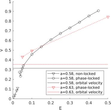
Refer to caption
Figure 5: Magnitude of spiral wave drift velocity in Barkley’s model (b=0.05𝑏0.05{\color[rgb]{0,0,1}b}=0.05, ς=0.02𝜍0.02{\color[rgb]{0,0,1}\varsigma}=0.02), far from resonance (a=0.58𝑎0.58{\color[rgb]{0,0,1}a}=0.58, black), and close to resonance (a=0.63𝑎0.63{\color[rgb]{0,0,1}a}=0.63, red). Close to the phase-locking threshold, the drift speed approaches the orbital velocity c=ωr𝑐𝜔𝑟{\color[rgb]{0,0,1}c}={\color[rgb]{0,0,1}\omega}{\color[rgb]{0,0,1}r}, with r𝑟{\color[rgb]{0,0,1}r}

the average radius of the meander flower.

Until here, we have described phase-locking of a single meander cycle to an external field, which happens when |ω|Ωmuch-less-than𝜔Ω\left\lvert{\color[rgb]{0,0,1}\omega}\right\rvert\ll{\color[rgb]{0,0,1}\Omega}. Since Ω=2π/TΩ2𝜋𝑇{\color[rgb]{0,0,1}\Omega}=2\pi/{\color[rgb]{0,0,1}T} and ω=β/T𝜔𝛽𝑇{\color[rgb]{0,0,1}\omega}={\color[rgb]{0,0,1}\beta}/{\color[rgb]{0,0,1}T} with β𝛽{\color[rgb]{0,0,1}\beta} the angle between subsequently visited petal tips, phase-locking is found generally when

β2πp,p.formulae-sequence𝛽2𝜋𝑝𝑝\displaystyle{\color[rgb]{0,0,1}\beta}\approx 2\pi{\color[rgb]{0,0,1}p},\qquad{\color[rgb]{0,0,1}p}\in\mathbb{Z}.

In some cases, a higher-order resonance may occur, i.e.

β2πp/q,p,q,q0formulae-sequence𝛽2𝜋𝑝𝑞𝑝formulae-sequence𝑞𝑞0\displaystyle{\color[rgb]{0,0,1}\beta}\approx 2\pi{\color[rgb]{0,0,1}p}/{\color[rgb]{0,0,1}q},\qquad{\color[rgb]{0,0,1}p},{\color[rgb]{0,0,1}q}\in\mathbb{Z},\;{\color[rgb]{0,0,1}q}\neq 0

(naturally, practical interest present cases of small p,q𝑝𝑞{\color[rgb]{0,0,1}p},{\color[rgb]{0,0,1}q}). In this case, q𝑞{\color[rgb]{0,0,1}q} meander cycles can be re-interpreted as a single cycle to which the theory (28)-(79) can be applied, with ω𝜔{\color[rgb]{0,0,1}\omega} replaced by qωpΩ𝑞𝜔𝑝Ω{\color[rgb]{0,0,1}q}{\color[rgb]{0,0,1}\omega}-{\color[rgb]{0,0,1}p}{\color[rgb]{0,0,1}\Omega}.

VIII.4 Regime close to phase-locking

It could happen that the applied field E𝐸{\color[rgb]{0,0,1}\vec{E}} is not strong enough to enforce phase-locking, which occurs when |E|<Ecrit𝐸subscript𝐸𝑐𝑟𝑖𝑡\left\lvert{\color[rgb]{0,0,1}E}\right\rvert<{\color[rgb]{0,0,1}E_{crit}}. In that case, the net drift can be found from the instant equations of motion (28) by averaging of one sort or another. In the case of circular core spirals, this was done by sliding time averaging Biktashev and Holden (1995) or by imposing condition of periodicity on the perturbed solution that in turn requiring a solvability condition Biktasheva et al. (2010). Since for meandering spirals the unperturbed solution is not periodic but biperiodic, the situation here requires a bit more care. In Dierckx et al. (2017b) we considered the case below but not too close to phase-locking threshold, and used Fourier series. For the case |E|Ecritless-than-or-similar-to𝐸subscript𝐸𝑐𝑟𝑖𝑡\left\lvert E\right\rvert\lesssim{\color[rgb]{0,0,1}E_{crit}}, this does not work, so we resort to the more robust method, by sliding averages. First we do averaging over the meander phase:

Φ¯(Ψ)=12πΨπΨ+πΦ(Ψ)dΨ.¯ΦΨ12𝜋superscriptsubscriptΨ𝜋Ψ𝜋ΦsuperscriptΨdifferential-dsuperscriptΨ\displaystyle\underline{{\color[rgb]{0,0,1}\Phi}}({\color[rgb]{0,0,1}\Psi})=\frac{1}{2\pi}\int_{{\color[rgb]{0,0,1}\Psi}-\pi}^{{\color[rgb]{0,0,1}\Psi}+\pi}{\color[rgb]{0,0,1}\Phi}({\color[rgb]{0,0,1}\Psi}^{\prime})\,\mathrm{d}{\color[rgb]{0,0,1}\Psi}^{\prime}.

Then, if |ω|Ωmuch-less-than𝜔Ω|{\color[rgb]{0,0,1}\omega}|\ll{\color[rgb]{0,0,1}\Omega},

tΦ¯=ω¯+MΦA¯RAa(Φ¯)Ea+𝒪(E2).subscript𝑡¯Φ¯𝜔¯subscriptsuperscriptMΦ𝐴subscriptsuperscript𝑅𝐴𝑎¯Φsuperscript𝐸𝑎𝒪superscript𝐸2\displaystyle\partial_{\color[rgb]{0,0,1}t}\underline{{\color[rgb]{0,0,1}\Phi}}=\overline{{\color[rgb]{0,0,1}\omega}}+\overline{{\color[rgb]{0,0,1}{\mathrm{M}^{{\color[rgb]{0,0,1}\Phi}}}_{{\color[rgb]{0,0,1}A}}}}{\color[rgb]{0,0,1}{R^{{\color[rgb]{0,0,1}A}}}_{{\color[rgb]{0,0,1}a}}}(\underline{{\color[rgb]{0,0,1}\Phi}}){\color[rgb]{0,0,1}E}^{\color[rgb]{0,0,1}a}+\mathcal{O}({\color[rgb]{0,0,1}E}^{2}). (80)

As above, we can write the second term in the right-hand side as EAcos(Φ¯α)𝐸𝐴¯Φ𝛼{\color[rgb]{0,0,1}E}{\color[rgb]{0,0,1}A}\cos({\color[rgb]{0,0,1}\overline{{\color[rgb]{0,0,1}\Phi}}}-{\color[rgb]{0,0,1}\alpha}). Let us denote the time needed to complete a full meander flower as

𝒯=2πω¯=2πβT.subscript𝒯2𝜋¯𝜔2𝜋𝛽𝑇\displaystyle{\color[rgb]{0,0,1}{\color[rgb]{0,0,1}\mathcal{T}}_{*}}=\frac{2\pi}{\overline{{\color[rgb]{0,0,1}\omega}}}=\frac{2\pi}{{\color[rgb]{0,0,1}\beta}}{\color[rgb]{0,0,1}T}.

Under a perturbation this value changes to 𝒯𝒯{\color[rgb]{0,0,1}\mathcal{T}}. Then, straightforward integration of Eq. (80) delivers:

𝒯=𝒯1(E/Ecrit)2.𝒯subscript𝒯1superscript𝐸subscript𝐸𝑐𝑟𝑖𝑡2\displaystyle{\color[rgb]{0,0,1}\mathcal{T}}=\frac{{\color[rgb]{0,0,1}{\color[rgb]{0,0,1}\mathcal{T}}_{*}}}{\sqrt{1-\left({\color[rgb]{0,0,1}E}/{\color[rgb]{0,0,1}E_{crit}}\right)^{2}}}.

Therefore, if E𝐸{\color[rgb]{0,0,1}E} approaches Ecritsubscript𝐸𝑐𝑟𝑖𝑡{\color[rgb]{0,0,1}E_{crit}} from below, the time needed to complete a full meander flower diverges. Beyond Ecritsubscript𝐸𝑐𝑟𝑖𝑡{\color[rgb]{0,0,1}E_{crit}} the spiral fails to complete a meander cycle and is phase-locked.

VIII.5 Average drift speed of a non-phase-locked meandering spiral
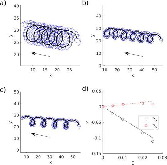
Refer to caption
Figure 6: Non phase-locked drift of a meandering spiral in Barkley’s model due to a constant external field E=Eex𝐸𝐸subscript𝑒𝑥{\color[rgb]{0,0,1}\vec{E}}={\color[rgb]{0,0,1}E}{\color[rgb]{0,0,1}\vec{e}_{x}}, for different field strengths: (a) E=0.01𝐸0.01{\color[rgb]{0,0,1}E}=0.01, (b) E=0.02𝐸0.02{\color[rgb]{0,0,1}E}=0.02, (c) E=0.025𝐸0.025{\color[rgb]{0,0,1}E}=0.025. Model parameters as in Fig. 1d and 𝐐=𝐏𝐐𝐏{\color[rgb]{0,0,1}{\mathbf{Q}}}={\color[rgb]{0,0,1}{\mathbf{P}}}. Panel d) shows the parallel and perpendicular components of drift (data points), which closely match the theoretical predictions given by Eq. (87) (lines).
Refer to caption
Figure 7: Same as Fig. 6, but for the Fenton-Karma guinea pig cardiac model from Fig. 1, which has a linear core. Applied field strengths are (a) E=0.005mm1𝐸0.005superscriptmm1{\color[rgb]{0,0,1}E}=0.005\,\mathrm{mm}^{-1}, (b) E=0.025mm1𝐸0.025superscriptmm1{\color[rgb]{0,0,1}E}=0.025\,\mathrm{mm}^{-1}, (c) E=0.06mm1𝐸0.06superscriptmm1{\color[rgb]{0,0,1}E}=0.06\,\mathrm{mm}^{-1}.

We continue our analysis of Eq. (28) in the regime where phase-locking does not occur, i.e. when β/2π𝛽2𝜋{\color[rgb]{0,0,1}\beta}/2\pi is not a simple fraction or when E𝐸E is sufficiently small, say E=𝒪(η)𝐸𝒪𝜂{\color[rgb]{0,0,1}E}=\mathcal{O}({\color[rgb]{0,0,1}\eta}).

For any of the reference frames shown in Fig. 3, we can in a first step integrate Eqs. (74) to find the net displacement in space, time and rotation angle during the single meander cycle, say the n𝑛{\color[rgb]{0,0,1}n}-th. At the start of this cycle, taking place at t=tn𝑡subscript𝑡𝑛{\color[rgb]{0,0,1}t}={\color[rgb]{0,0,1}t}_{\color[rgb]{0,0,1}n} the collective coordinates of the spiral are denoted Xna,Φn,Ψnsubscriptsuperscript𝑋𝑎𝑛subscriptΦ𝑛subscriptΨ𝑛{\color[rgb]{0,0,1}X}^{{\color[rgb]{0,0,1}a}}_{{\color[rgb]{0,0,1}n}},{\color[rgb]{0,0,1}\Phi}_{\color[rgb]{0,0,1}n},{\color[rgb]{0,0,1}\Psi}_{\color[rgb]{0,0,1}n}.

For t[tn,tn+1]𝑡subscript𝑡𝑛subscript𝑡𝑛1{\color[rgb]{0,0,1}t}\in[{\color[rgb]{0,0,1}t}_{n},{\color[rgb]{0,0,1}t}_{n+1}], we can write:

Ψ(t)Ψ𝑡\displaystyle{\color[rgb]{0,0,1}\Psi}({\color[rgb]{0,0,1}t}) =Ψn+Ψ(t)+Ψ~(t)absentsubscriptΨ𝑛subscriptΨ𝑡~Ψ𝑡\displaystyle={\color[rgb]{0,0,1}\Psi}_{\color[rgb]{0,0,1}n}+{\color[rgb]{0,0,1}\Psi}_{*}({\color[rgb]{0,0,1}t})+\tilde{{\color[rgb]{0,0,1}\Psi}}({\color[rgb]{0,0,1}t})
Φ(t)Φ𝑡\displaystyle{\color[rgb]{0,0,1}\Phi}({\color[rgb]{0,0,1}t}) =Φn+Φ(t)+Φ~(t)absentsubscriptΦ𝑛subscriptΦ𝑡~Φ𝑡\displaystyle={\color[rgb]{0,0,1}\Phi}_{\color[rgb]{0,0,1}n}+{\color[rgb]{0,0,1}\Phi}_{*}({\color[rgb]{0,0,1}t})+\tilde{{\color[rgb]{0,0,1}\Phi}}({\color[rgb]{0,0,1}t})
Xa(t)superscript𝑋𝑎𝑡\displaystyle{{\color[rgb]{0,0,1}X}^{\color[rgb]{0,0,1}a}({\color[rgb]{0,0,1}t})} =Xna+Xa(t)+X~a(t).absentsubscriptsuperscript𝑋𝑎𝑛superscriptsubscript𝑋𝑎𝑡superscript~𝑋𝑎𝑡\displaystyle={\color[rgb]{0,0,1}X}^{{\color[rgb]{0,0,1}a}}_{{\color[rgb]{0,0,1}n}}+{\color[rgb]{0,0,1}X}_{*}^{\color[rgb]{0,0,1}a}({\color[rgb]{0,0,1}t})+\tilde{{\color[rgb]{0,0,1}X}}^{\color[rgb]{0,0,1}a}({\color[rgb]{0,0,1}t}).

In these right-hand sides, the first term is the initial value at the start of the n𝑛{\color[rgb]{0,0,1}n}-th cycle, the second term is the evolution in the unperturbed case, and the third term the correction to it, of 𝒪(E)𝒪𝐸\mathcal{O}({\color[rgb]{0,0,1}E}). Without loss of generality, we can set the n𝑛{\color[rgb]{0,0,1}n}-th cycle to start at Ψ=Ψn=2πnΨsubscriptΨ𝑛2𝜋𝑛{\color[rgb]{0,0,1}\Psi}={\color[rgb]{0,0,1}\Psi}_{n}=2\pi{\color[rgb]{0,0,1}n}.

The unperturbed evolution is given by

Ψ(t)subscriptΨ𝑡\displaystyle{\color[rgb]{0,0,1}\Psi}_{*}({\color[rgb]{0,0,1}t}) =Ω(ttn)absentΩ𝑡subscript𝑡𝑛\displaystyle={\color[rgb]{0,0,1}\Omega}({\color[rgb]{0,0,1}t}-{\color[rgb]{0,0,1}t}_{\color[rgb]{0,0,1}n})
Φ(t)subscriptΦ𝑡\displaystyle{\color[rgb]{0,0,1}\Phi}_{*}({\color[rgb]{0,0,1}t}) =tntω(Ψ(t))dtabsentsuperscriptsubscriptsubscript𝑡𝑛𝑡𝜔subscriptΨsuperscript𝑡differential-dsuperscript𝑡\displaystyle=\int_{{\color[rgb]{0,0,1}t}_{\color[rgb]{0,0,1}n}}^{\color[rgb]{0,0,1}t}{\color[rgb]{0,0,1}\omega}({{\color[rgb]{0,0,1}\Psi}_{*}({\color[rgb]{0,0,1}t}^{\prime})})\,{\mathrm{d}{\color[rgb]{0,0,1}t}^{\prime}}
Xa(t)superscriptsubscript𝑋𝑎𝑡\displaystyle{{\color[rgb]{0,0,1}X}_{*}^{\color[rgb]{0,0,1}a}}({\color[rgb]{0,0,1}t}) =tntRaA(Φ(t))cA(Ψ(t))dtabsentsuperscriptsubscriptsubscript𝑡𝑛𝑡subscriptsuperscript𝑅𝑎𝐴subscriptΦsuperscript𝑡superscript𝑐𝐴subscriptΨsuperscript𝑡differential-dsuperscript𝑡\displaystyle=\int_{{\color[rgb]{0,0,1}t}_{\color[rgb]{0,0,1}n}}^{\color[rgb]{0,0,1}t}{\color[rgb]{0,0,1}{R^{{\color[rgb]{0,0,1}a}}}_{{\color[rgb]{0,0,1}A}}}({{\color[rgb]{0,0,1}\Phi}_{*}({\color[rgb]{0,0,1}t}^{\prime})}){\color[rgb]{0,0,1}{\color[rgb]{0,0,1}c}^{{\color[rgb]{0,0,1}A}}}({{\color[rgb]{0,0,1}\Psi}_{*}({\color[rgb]{0,0,1}t}^{\prime})})\,{\mathrm{d}{\color[rgb]{0,0,1}t}^{\prime}}

Due to the group structure of rotations, we can write

RAa(Φ)=RAα(Φ)Rαβ(Φ~)Rβa(Φn),Rαβ(Φ~)=δαβcosΦ~+ϵαβsinΦ~=δαβ+ϵαβΦ~+𝒪(η2).formulae-sequencesubscriptsuperscript𝑅𝐴𝑎Φsubscriptsuperscript𝑅𝐴𝛼subscriptΦsubscriptsuperscript𝑅𝛼𝛽~Φsubscriptsuperscript𝑅𝛽𝑎subscriptΦ𝑛subscriptsuperscript𝑅𝛼𝛽~Φsubscriptsuperscript𝛿𝛼𝛽~Φsubscriptsuperscriptitalic-ϵ𝛼𝛽~Φsubscriptsuperscript𝛿𝛼𝛽subscriptsuperscriptitalic-ϵ𝛼𝛽~Φ𝒪superscript𝜂2\begin{split}{\color[rgb]{0,0,1}{R^{{\color[rgb]{0,0,1}A}}}_{{\color[rgb]{0,0,1}a}}}({\color[rgb]{0,0,1}\Phi})&={\color[rgb]{0,0,1}{R^{{\color[rgb]{0,0,1}A}}}_{{\color[rgb]{0,0,1}\alpha}}}({{\color[rgb]{0,0,1}\Phi}_{*}}){\color[rgb]{0,0,1}{R^{{\color[rgb]{0,0,1}\alpha}}}_{{\color[rgb]{0,0,1}\beta}}}({\tilde{{\color[rgb]{0,0,1}\Phi}}}){\color[rgb]{0,0,1}{R^{{\color[rgb]{0,0,1}\beta}}}_{{\color[rgb]{0,0,1}a}}}({\color[rgb]{0,0,1}\Phi}_{n}),\\ {\color[rgb]{0,0,1}{R^{{\color[rgb]{0,0,1}\alpha}}}_{{\color[rgb]{0,0,1}\beta}}}({\tilde{{\color[rgb]{0,0,1}\Phi}}})&={\color[rgb]{0,0,1}{\delta^{{\color[rgb]{0,0,1}\alpha}}}_{{\color[rgb]{0,0,1}\beta}}}\cos{\tilde{{\color[rgb]{0,0,1}\Phi}}}+{\color[rgb]{0,0,1}{{\color[rgb]{0,0,1}\epsilon}^{{\color[rgb]{0,0,1}\alpha}}}_{{\color[rgb]{0,0,1}\beta}}}\sin{\tilde{{\color[rgb]{0,0,1}\Phi}}}={\color[rgb]{0,0,1}{\delta^{{\color[rgb]{0,0,1}\alpha}}}_{{\color[rgb]{0,0,1}\beta}}}+{\color[rgb]{0,0,1}{{\color[rgb]{0,0,1}\epsilon}^{{\color[rgb]{0,0,1}\alpha}}}_{{\color[rgb]{0,0,1}\beta}}}{\tilde{{\color[rgb]{0,0,1}\Phi}}}+\mathcal{O}({\color[rgb]{0,0,1}\eta}^{2}).\end{split} (81)

We will below use

Mμα(Ψ(t))=MμA(Ψ(t))RAα(Φ(t)),μ{Φ,Ψ}Mαβ(Ψ(t))=RαA(Φ(t))MAB(Ψ(t))RAα(Φ(t)),cα(Ψ(t))=RαA(Φ(t))cA(Ψ)\begin{split}{{\color[rgb]{0,0,1}{\mathrm{M}^{{\color[rgb]{0,0,1}\mu}}}_{{\color[rgb]{0,0,1}\alpha}}}({\color[rgb]{0,0,1}\Psi}_{*}({\color[rgb]{0,0,1}t}))}&={{\color[rgb]{0,0,1}{\mathrm{M}^{{\color[rgb]{0,0,1}\mu}}}_{{\color[rgb]{0,0,1}A}}}({\color[rgb]{0,0,1}\Psi}_{*}({\color[rgb]{0,0,1}t})){\color[rgb]{0,0,1}{R^{{\color[rgb]{0,0,1}A}}}_{{\color[rgb]{0,0,1}\alpha}}}({\color[rgb]{0,0,1}\Phi}_{*}({\color[rgb]{0,0,1}t})),\qquad{\color[rgb]{0,0,1}\mu}\in\{{\color[rgb]{0,0,1}\Phi},{\color[rgb]{0,0,1}\Psi}\}}\\ {\color[rgb]{0,0,1}{\mathrm{M}^{{\color[rgb]{0,0,1}\alpha}}}_{{\color[rgb]{0,0,1}\beta}}}({{\color[rgb]{0,0,1}\Psi}_{*}}({\color[rgb]{0,0,1}t}))&={\color[rgb]{0,0,1}{R^{{\color[rgb]{0,0,1}\alpha}}}_{{\color[rgb]{0,0,1}A}}}({{\color[rgb]{0,0,1}\Phi}_{*}}({\color[rgb]{0,0,1}t})){\color[rgb]{0,0,1}{\mathrm{M}^{{\color[rgb]{0,0,1}A}}}_{{\color[rgb]{0,0,1}B}}}({{\color[rgb]{0,0,1}\Psi}_{*}}({\color[rgb]{0,0,1}t})){\color[rgb]{0,0,1}{R^{{\color[rgb]{0,0,1}A}}}_{{\color[rgb]{0,0,1}\alpha}}}({{\color[rgb]{0,0,1}\Phi}_{*}}({\color[rgb]{0,0,1}t})),\\ {\color[rgb]{0,0,1}{\color[rgb]{0,0,1}c}^{{\color[rgb]{0,0,1}\alpha}}}({{\color[rgb]{0,0,1}\Psi}_{*}}({\color[rgb]{0,0,1}t}))&={\color[rgb]{0,0,1}{R^{{\color[rgb]{0,0,1}\alpha}}}_{{\color[rgb]{0,0,1}A}}}({{\color[rgb]{0,0,1}\Phi}_{*}}({\color[rgb]{0,0,1}t})){\color[rgb]{0,0,1}{\color[rgb]{0,0,1}c}^{{\color[rgb]{0,0,1}A}}}({\color[rgb]{0,0,1}\Psi})\end{split} (82)

Note that these functions are not periodic in ΨΨ{\color[rgb]{0,0,1}\Psi} anymore.

With Eqs. (81)-(82), the evolution equation for ΨΨ{\color[rgb]{0,0,1}\Psi} becomes

tΨ=Ω+MΨβ(Ψ(t))Rβb(Φn)Eb+𝒪(η2).subscript𝑡ΨΩsubscriptsuperscriptMΨ𝛽subscriptΨ𝑡subscriptsuperscript𝑅𝛽𝑏subscriptΦ𝑛superscript𝐸𝑏𝒪superscript𝜂2\displaystyle{\partial_{\color[rgb]{0,0,1}t}}{\color[rgb]{0,0,1}\Psi}={\color[rgb]{0,0,1}\Omega}+{\color[rgb]{0,0,1}{\mathrm{M}^{{\color[rgb]{0,0,1}\Psi}}}_{{\color[rgb]{0,0,1}\beta}}}({{\color[rgb]{0,0,1}\Psi}_{*}}({\color[rgb]{0,0,1}t})){\color[rgb]{0,0,1}{R^{{\color[rgb]{0,0,1}\beta}}}_{{\color[rgb]{0,0,1}b}}}({\color[rgb]{0,0,1}\Phi}_{\color[rgb]{0,0,1}n}){\color[rgb]{0,0,1}E}^{\color[rgb]{0,0,1}b}+\mathcal{O}({\color[rgb]{0,0,1}\eta}^{2}). (83)

Since ΦnsubscriptΦ𝑛{\color[rgb]{0,0,1}\Phi}_{\color[rgb]{0,0,1}n} is constant, Eq. (83) yields the duration of the meander period in the presence of a constant external field E𝐸{\color[rgb]{0,0,1}\vec{E}}:

Tn=tn+1tn=tntn+1dt=02πdΨΩ+MΨαRαa(Φn)Ea=T(1Ω1MΨα¯Rαa(Φn)Ea)+𝒪(η2).subscript𝑇𝑛subscript𝑡𝑛1subscript𝑡𝑛superscriptsubscriptsubscript𝑡𝑛subscript𝑡𝑛1differential-d𝑡superscriptsubscript02𝜋dΨΩsubscriptsuperscriptMΨ𝛼subscriptsuperscript𝑅𝛼𝑎subscriptΦ𝑛superscript𝐸𝑎𝑇1superscriptΩ1¯subscriptsuperscriptMΨ𝛼subscriptsuperscript𝑅𝛼𝑎subscriptΦ𝑛superscript𝐸𝑎𝒪superscript𝜂2\begin{split}{\color[rgb]{0,0,1}T}_{\color[rgb]{0,0,1}n}&={\color[rgb]{0,0,1}t}_{{\color[rgb]{0,0,1}n}+1}-{\color[rgb]{0,0,1}t}_{\color[rgb]{0,0,1}n}=\int_{{\color[rgb]{0,0,1}t}_{\color[rgb]{0,0,1}n}}^{{\color[rgb]{0,0,1}t}_{{\color[rgb]{0,0,1}n}+1}}\,\mathrm{d}{\color[rgb]{0,0,1}t}=\int_{0}^{2\pi}\frac{\mathrm{d}{\color[rgb]{0,0,1}\Psi}}{{\color[rgb]{0,0,1}\Omega}+{\color[rgb]{0,0,1}{\mathrm{M}^{{\color[rgb]{0,0,1}\Psi}}}_{{\color[rgb]{0,0,1}\alpha}}}{\color[rgb]{0,0,1}{R^{{\color[rgb]{0,0,1}\alpha}}}_{{\color[rgb]{0,0,1}a}}}({\color[rgb]{0,0,1}\Phi}_{\color[rgb]{0,0,1}n}){\color[rgb]{0,0,1}E}^{\color[rgb]{0,0,1}a}}\\ &={\color[rgb]{0,0,1}T}\left(1-{\color[rgb]{0,0,1}\Omega}^{-1}\overline{{\color[rgb]{0,0,1}{\mathrm{M}^{{\color[rgb]{0,0,1}\Psi}}}_{{\color[rgb]{0,0,1}\alpha}}}}{\color[rgb]{0,0,1}{R^{{\color[rgb]{0,0,1}\alpha}}}_{{\color[rgb]{0,0,1}a}}}({\color[rgb]{0,0,1}\Phi}_{\color[rgb]{0,0,1}n}){\color[rgb]{0,0,1}E}^{\color[rgb]{0,0,1}a}\right)+\mathcal{O}({\color[rgb]{0,0,1}\eta}^{2}).\end{split} (84)

Note that the resulting period depends on ΦnsubscriptΦ𝑛{\color[rgb]{0,0,1}\Phi}_{\color[rgb]{0,0,1}n}, i.e. on the orientation of the trajectory relative to the applied field E𝐸{\color[rgb]{0,0,1}\vec{E}}.

The rotation phase during one cycle can be found by integrating ΨΦ=tΦ/tΨsubscriptΨΦsubscript𝑡Φsubscript𝑡Ψ\partial_{\color[rgb]{0,0,1}\Psi}{\color[rgb]{0,0,1}\Phi}=\partial_{\color[rgb]{0,0,1}t}{\color[rgb]{0,0,1}\Phi}/\partial_{\color[rgb]{0,0,1}t}{\color[rgb]{0,0,1}\Psi}:

Φ(Ψ)ΦnΦΨsubscriptΦ𝑛\displaystyle{\color[rgb]{0,0,1}\Phi}({\color[rgb]{0,0,1}\Psi})-{\color[rgb]{0,0,1}\Phi}_{\color[rgb]{0,0,1}n} =ΨnΨω(Ψ)+MΦα(Ψ)Rαa(Φn)EaΩ+MΨα(Ψ)Rαa(Φn)EadΨabsentsuperscriptsubscriptsubscriptΨ𝑛Ψ𝜔ΨsubscriptsuperscriptMΦ𝛼Ψsubscriptsuperscript𝑅𝛼𝑎subscriptΦ𝑛superscript𝐸𝑎ΩsubscriptsuperscriptMΨ𝛼Ψsubscriptsuperscript𝑅𝛼𝑎subscriptΦ𝑛superscript𝐸𝑎differential-dΨ\displaystyle=\int_{{\color[rgb]{0,0,1}\Psi}_{\color[rgb]{0,0,1}n}}^{{\color[rgb]{0,0,1}\Psi}}\frac{{\color[rgb]{0,0,1}\omega}({\color[rgb]{0,0,1}\Psi})+{\color[rgb]{0,0,1}{\mathrm{M}^{{\color[rgb]{0,0,1}\Phi}}}_{{\color[rgb]{0,0,1}\alpha}}}({\color[rgb]{0,0,1}\Psi}){\color[rgb]{0,0,1}{R^{{\color[rgb]{0,0,1}\alpha}}}_{{\color[rgb]{0,0,1}a}}}({\color[rgb]{0,0,1}\Phi}_{\color[rgb]{0,0,1}n}){{\color[rgb]{0,0,1}E}^{\color[rgb]{0,0,1}a}}}{{\color[rgb]{0,0,1}\Omega}+{\color[rgb]{0,0,1}{\mathrm{M}^{{\color[rgb]{0,0,1}\Psi}}}_{{\color[rgb]{0,0,1}\alpha}}}({\color[rgb]{0,0,1}\Psi}){\color[rgb]{0,0,1}{R^{{\color[rgb]{0,0,1}\alpha}}}_{{\color[rgb]{0,0,1}a}}}({\color[rgb]{0,0,1}\Phi}_{\color[rgb]{0,0,1}n}){{\color[rgb]{0,0,1}E}^{\color[rgb]{0,0,1}a}}}\mathrm{d}{\color[rgb]{0,0,1}\Psi}
=Φ+NΦαRαa(Φn)Ea+𝒪(η2),absentsubscriptΦsubscriptsuperscript𝑁Φ𝛼subscriptsuperscript𝑅𝛼𝑎subscriptΦ𝑛superscript𝐸𝑎𝒪superscript𝜂2\displaystyle={{\color[rgb]{0,0,1}\Phi}_{*}}+{\color[rgb]{0,0,1}{N^{{\color[rgb]{0,0,1}\Phi}}}_{{\color[rgb]{0,0,1}\alpha}}}{\color[rgb]{0,0,1}{R^{{\color[rgb]{0,0,1}\alpha}}}_{{\color[rgb]{0,0,1}a}}}({\color[rgb]{0,0,1}\Phi}_{\color[rgb]{0,0,1}n}){{\color[rgb]{0,0,1}E}^{\color[rgb]{0,0,1}a}}+\mathcal{O}({\color[rgb]{0,0,1}\eta}^{2}),

where

NΦα(Ψ)subscriptsuperscript𝑁Φ𝛼Ψ\displaystyle{\color[rgb]{0,0,1}{N^{{\color[rgb]{0,0,1}\Phi}}}_{{\color[rgb]{0,0,1}\alpha}}}({\color[rgb]{0,0,1}\Psi}) =Ω1ΨnΨmα(Ψ)dΨ,absentsuperscriptΩ1superscriptsubscriptsubscriptΨ𝑛Ψsubscript𝑚𝛼superscriptΨdifferential-dsuperscriptΨ\displaystyle={\color[rgb]{0,0,1}\Omega}^{-1}\int_{{\color[rgb]{0,0,1}\Psi}_{\color[rgb]{0,0,1}n}}^{\color[rgb]{0,0,1}\Psi}{\color[rgb]{0,0,1}m_{{\color[rgb]{0,0,1}\alpha}}}({\color[rgb]{0,0,1}\Psi}^{\prime})\,\mathrm{d}{\color[rgb]{0,0,1}\Psi}^{\prime},
mα(Ψ)subscript𝑚𝛼Ψ\displaystyle{\color[rgb]{0,0,1}m_{{\color[rgb]{0,0,1}\alpha}}}({\color[rgb]{0,0,1}\Psi}) =MΦα(Ψ)Ω1TωMΨα(Ψ).absentsubscriptsuperscriptMΦ𝛼ΨsuperscriptΩ1𝑇𝜔subscriptsuperscriptMΨ𝛼Ψ\displaystyle={\color[rgb]{0,0,1}{\mathrm{M}^{{\color[rgb]{0,0,1}\Phi}}}_{{\color[rgb]{0,0,1}\alpha}}}({\color[rgb]{0,0,1}\Psi})-{\color[rgb]{0,0,1}\Omega}^{-1}{\color[rgb]{0,0,1}T}{\color[rgb]{0,0,1}\omega}\,{\color[rgb]{0,0,1}{\mathrm{M}^{{\color[rgb]{0,0,1}\Psi}}}_{{\color[rgb]{0,0,1}\alpha}}}({\color[rgb]{0,0,1}\Psi}).

Evaluation at Ψn+1subscriptΨ𝑛1{\color[rgb]{0,0,1}\Psi}_{{\color[rgb]{0,0,1}n}+1} delivers the change in rotation angle over one meander period:

βn=Φn+1Φn=β+Tmα¯Rαa(Φn)Ea+𝒪(η2),subscript𝛽𝑛subscriptΦ𝑛1subscriptΦ𝑛𝛽𝑇¯subscript𝑚𝛼subscriptsuperscript𝑅𝛼𝑎subscriptΦ𝑛superscript𝐸𝑎𝒪superscript𝜂2\begin{split}{\color[rgb]{0,0,1}\beta}_{\color[rgb]{0,0,1}n}&={\color[rgb]{0,0,1}\Phi}_{{\color[rgb]{0,0,1}n}+1}-{\color[rgb]{0,0,1}\Phi}_{\color[rgb]{0,0,1}n}\\ &={\color[rgb]{0,0,1}\beta}+{\color[rgb]{0,0,1}T}\,\overline{{\color[rgb]{0,0,1}m_{{\color[rgb]{0,0,1}\alpha}}}}\,{\color[rgb]{0,0,1}{R^{{\color[rgb]{0,0,1}\alpha}}}_{{\color[rgb]{0,0,1}a}}}({\color[rgb]{0,0,1}\Phi}_{\color[rgb]{0,0,1}n}){\color[rgb]{0,0,1}E}^{\color[rgb]{0,0,1}a}+\mathcal{O}({\color[rgb]{0,0,1}\eta}^{2}),\end{split} (85)

Hence, an applied field will change the angle between consecutively visited petals of the meander flower.

Finally, we can find the net spatial displacement during a meander cycle:

dna=subscriptsuperscript𝑑𝑎𝑛absent\displaystyle{\color[rgb]{0,0,1}d}^{{\color[rgb]{0,0,1}a}}_{{\color[rgb]{0,0,1}n}}= Xn+1aXnasubscriptsuperscript𝑋𝑎𝑛1subscriptsuperscript𝑋𝑎𝑛\displaystyle{\color[rgb]{0,0,1}X}^{{\color[rgb]{0,0,1}a}}_{{\color[rgb]{0,0,1}n}+1}-{\color[rgb]{0,0,1}X}^{{\color[rgb]{0,0,1}a}}_{{\color[rgb]{0,0,1}n}}
=\displaystyle= da+TRaα(Φn)mαβ¯Rβb(Φn)Eb+𝒪(η2),superscript𝑑𝑎𝑇subscriptsuperscript𝑅𝑎𝛼subscriptΦ𝑛¯subscriptsuperscriptm𝛼𝛽subscriptsuperscript𝑅𝛽𝑏subscriptΦ𝑛superscript𝐸𝑏𝒪superscript𝜂2\displaystyle{\color[rgb]{0,0,1}d}^{\color[rgb]{0,0,1}a}+{\color[rgb]{0,0,1}T}{\color[rgb]{0,0,1}{R^{{\color[rgb]{0,0,1}a}}}_{{\color[rgb]{0,0,1}\alpha}}}({\color[rgb]{0,0,1}\Phi}_{\color[rgb]{0,0,1}n})\overline{{\color[rgb]{0,0,1}{\mathrm{m}^{{\color[rgb]{0,0,1}\alpha}}}_{{\color[rgb]{0,0,1}\beta}}}}{\color[rgb]{0,0,1}{R^{{\color[rgb]{0,0,1}\beta}}}_{{\color[rgb]{0,0,1}b}}}({\color[rgb]{0,0,1}\Phi}_{\color[rgb]{0,0,1}n}){\color[rgb]{0,0,1}E}^{\color[rgb]{0,0,1}b}+\mathcal{O}({\color[rgb]{0,0,1}\eta}^{2}),

where

mαβ=MαβΩ1[cαMΨβϵαγcγNΦβ].subscriptsuperscriptm𝛼𝛽subscriptsuperscriptM𝛼𝛽superscriptΩ1delimited-[]superscript𝑐𝛼subscriptsuperscriptMΨ𝛽subscriptsuperscriptitalic-ϵ𝛼𝛾superscript𝑐𝛾subscriptsuperscript𝑁Φ𝛽\displaystyle{\color[rgb]{0,0,1}{\mathrm{m}^{{\color[rgb]{0,0,1}\alpha}}}_{{\color[rgb]{0,0,1}\beta}}}={\color[rgb]{0,0,1}{\mathrm{M}^{{\color[rgb]{0,0,1}\alpha}}}_{{\color[rgb]{0,0,1}\beta}}}-{\color[rgb]{0,0,1}\Omega}^{-1}\left[{\color[rgb]{0,0,1}{\color[rgb]{0,0,1}c}^{{\color[rgb]{0,0,1}\alpha}}}{\color[rgb]{0,0,1}{\mathrm{M}^{{\color[rgb]{0,0,1}\Psi}}}_{{\color[rgb]{0,0,1}\beta}}}-{\color[rgb]{0,0,1}{{\color[rgb]{0,0,1}\epsilon}^{{\color[rgb]{0,0,1}\alpha}}}_{{\color[rgb]{0,0,1}\gamma}}}{\color[rgb]{0,0,1}{\color[rgb]{0,0,1}c}^{{\color[rgb]{0,0,1}\gamma}}}{\color[rgb]{0,0,1}{N^{{\color[rgb]{0,0,1}\Phi}}}_{{\color[rgb]{0,0,1}\beta}}}\right]. (86)

Thus, the net drift of a meandering spiral in an external field depends on the angle ΦΦ{\color[rgb]{0,0,1}\Phi} between the meander pattern and the applied field E𝐸{\color[rgb]{0,0,1}\vec{E}}.

The average drift speed, measured over one meander period (i.e. one petal of the flower) will be:

Vna=subscriptsuperscript𝑉𝑎𝑛absent\displaystyle{{\color[rgb]{0,0,1}V}^{{\color[rgb]{0,0,1}a}}_{{\color[rgb]{0,0,1}n}}}= dna/Tn=Raα(Φn)Qαβcα¯subscriptsuperscript𝑑𝑎𝑛subscript𝑇𝑛subscriptsuperscript𝑅𝑎𝛼subscriptΦ𝑛subscriptsuperscript𝑄𝛼𝛽¯superscript𝑐𝛼\displaystyle{{\color[rgb]{0,0,1}d}^{{\color[rgb]{0,0,1}a}}_{{\color[rgb]{0,0,1}n}}}/{\color[rgb]{0,0,1}T}_{\color[rgb]{0,0,1}n}={\color[rgb]{0,0,1}{R^{{\color[rgb]{0,0,1}a}}}_{{\color[rgb]{0,0,1}\alpha}}}({\color[rgb]{0,0,1}\Phi}_{\color[rgb]{0,0,1}n}){\color[rgb]{0,0,1}{Q^{{\color[rgb]{0,0,1}\alpha}}}_{{\color[rgb]{0,0,1}\beta}}}\overline{{\color[rgb]{0,0,1}{\color[rgb]{0,0,1}c}^{{\color[rgb]{0,0,1}\alpha}}}}
+Raα(Φn)Rβb(Φn)Eb+𝒪(η2).subscriptsuperscript𝑅𝑎𝛼subscriptΦ𝑛subscriptsuperscript𝑅𝛽𝑏subscriptΦ𝑛superscript𝐸𝑏𝒪superscript𝜂2\displaystyle+{\color[rgb]{0,0,1}{R^{{\color[rgb]{0,0,1}a}}}_{{\color[rgb]{0,0,1}\alpha}}}({\color[rgb]{0,0,1}\Phi}_{\color[rgb]{0,0,1}n}){\color[rgb]{0,0,1}{R^{{\color[rgb]{0,0,1}\beta}}}_{{\color[rgb]{0,0,1}b}}}({\color[rgb]{0,0,1}\Phi}_{\color[rgb]{0,0,1}n}){\color[rgb]{0,0,1}E}^{\color[rgb]{0,0,1}b}+\mathcal{O}({\color[rgb]{0,0,1}\eta}^{2}).

with

Qαβ=mαβ¯+cα¯MΨβ¯Ωsubscriptsuperscript𝑄𝛼𝛽¯subscriptsuperscriptm𝛼𝛽¯superscript𝑐𝛼¯subscriptsuperscriptMΨ𝛽Ω\displaystyle{\color[rgb]{0,0,1}{Q^{{\color[rgb]{0,0,1}\alpha}}}_{{\color[rgb]{0,0,1}\beta}}}=\overline{{\color[rgb]{0,0,1}{\mathrm{m}^{{\color[rgb]{0,0,1}\alpha}}}_{{\color[rgb]{0,0,1}\beta}}}}+\frac{\overline{{\color[rgb]{0,0,1}{\color[rgb]{0,0,1}c}^{{\color[rgb]{0,0,1}\alpha}}}}\overline{{\color[rgb]{0,0,1}{\mathrm{M}^{{\color[rgb]{0,0,1}\Psi}}}_{{\color[rgb]{0,0,1}\beta}}}}}{{\color[rgb]{0,0,1}\Omega}}

If we are outside the phase-locking regime, the ratio β/2π=ω/Ω𝛽2𝜋𝜔Ω{\color[rgb]{0,0,1}\beta}/2\pi={\color[rgb]{0,0,1}\omega}/{\color[rgb]{0,0,1}\Omega} will not be close to a fraction p/q𝑝𝑞{\color[rgb]{0,0,1}p}/{\color[rgb]{0,0,1}q} with p𝑝{\color[rgb]{0,0,1}p} and q𝑞{\color[rgb]{0,0,1}q} small integers. Therefore, after several rotations, the angle ΦnsubscriptΦ𝑛{\color[rgb]{0,0,1}\Phi}_{\color[rgb]{0,0,1}n} will have taken different values that are uniformly distributed over the unit circle. In that approximation, the time average of a quantity (net rotation, displacement or time lapse) will be that quantity averaged over all possible phases ΦnsubscriptΦ𝑛{\color[rgb]{0,0,1}\Phi}_{\color[rgb]{0,0,1}n} at the start of the meander cycle:

Tdelimited-⟨⟩𝑇\displaystyle\langle{\color[rgb]{0,0,1}T}\rangle =limmtn+mtnm=12π02πTn(Φn)dΦn,absentsubscript𝑚subscript𝑡𝑛𝑚subscript𝑡𝑛𝑚12𝜋superscriptsubscript02𝜋subscript𝑇𝑛subscriptΦ𝑛differential-dsubscriptΦ𝑛\displaystyle=\lim_{{\color[rgb]{0,0,1}m}\rightarrow\infty}\frac{{\color[rgb]{0,0,1}t}_{{\color[rgb]{0,0,1}n}+{\color[rgb]{0,0,1}m}}-{\color[rgb]{0,0,1}t}_{\color[rgb]{0,0,1}n}}{{\color[rgb]{0,0,1}m}}=\frac{1}{2\pi}\int_{0}^{2\pi}{\color[rgb]{0,0,1}T}_{\color[rgb]{0,0,1}n}({\color[rgb]{0,0,1}\Phi}_{\color[rgb]{0,0,1}n})\,\mathrm{d}{\color[rgb]{0,0,1}\Phi}_{\color[rgb]{0,0,1}n},
βdelimited-⟨⟩𝛽\displaystyle\langle{\color[rgb]{0,0,1}\beta}\rangle =limmΦn+mΦnm=12π02πβn(Φn)dΦn,absentsubscript𝑚subscriptΦ𝑛𝑚subscriptΦ𝑛𝑚12𝜋superscriptsubscript02𝜋subscript𝛽𝑛subscriptΦ𝑛differential-dsubscriptΦ𝑛\displaystyle=\lim_{{\color[rgb]{0,0,1}m}\rightarrow\infty}\frac{{\color[rgb]{0,0,1}\Phi}_{{\color[rgb]{0,0,1}n}+{\color[rgb]{0,0,1}m}}-{\color[rgb]{0,0,1}\Phi}_{\color[rgb]{0,0,1}n}}{{\color[rgb]{0,0,1}m}}=\frac{1}{2\pi}\int_{0}^{2\pi}{\color[rgb]{0,0,1}\beta}_{\color[rgb]{0,0,1}n}({\color[rgb]{0,0,1}\Phi}_{\color[rgb]{0,0,1}n})\,\mathrm{d}{\color[rgb]{0,0,1}\Phi}_{\color[rgb]{0,0,1}n},
dadelimited-⟨⟩superscript𝑑𝑎\displaystyle\langle{\color[rgb]{0,0,1}d}^{\color[rgb]{0,0,1}a}\rangle =limmXn+maXnam=12π02πdna(Φn)dΦn,absentsubscript𝑚subscriptsuperscript𝑋𝑎𝑛𝑚subscriptsuperscript𝑋𝑎𝑛𝑚12𝜋superscriptsubscript02𝜋subscriptsuperscript𝑑𝑎𝑛subscriptΦ𝑛differential-dsubscriptΦ𝑛\displaystyle=\lim_{{\color[rgb]{0,0,1}m}\rightarrow\infty}\frac{{{\color[rgb]{0,0,1}X}^{{\color[rgb]{0,0,1}a}}_{{\color[rgb]{0,0,1}n}+{\color[rgb]{0,0,1}m}}-{\color[rgb]{0,0,1}X}^{{\color[rgb]{0,0,1}a}}_{{\color[rgb]{0,0,1}n}}}}{{\color[rgb]{0,0,1}m}}=\frac{1}{2\pi}\int_{0}^{2\pi}{{\color[rgb]{0,0,1}d}^{{\color[rgb]{0,0,1}a}}_{{\color[rgb]{0,0,1}n}}}({\color[rgb]{0,0,1}\Phi}_{\color[rgb]{0,0,1}n})\,\mathrm{d}{\color[rgb]{0,0,1}\Phi}_{\color[rgb]{0,0,1}n},
Vadelimited-⟨⟩superscript𝑉𝑎\displaystyle\langle{\color[rgb]{0,0,1}V}^{\color[rgb]{0,0,1}a}\rangle =limmXn+maXnatn+mtn=12π02πVna(Φn)dΦn.absentsubscript𝑚subscriptsuperscript𝑋𝑎𝑛𝑚subscriptsuperscript𝑋𝑎𝑛subscript𝑡𝑛𝑚subscript𝑡𝑛12𝜋superscriptsubscript02𝜋subscriptsuperscript𝑉𝑎𝑛subscriptΦ𝑛differential-dsubscriptΦ𝑛\displaystyle=\lim_{{\color[rgb]{0,0,1}m}\rightarrow\infty}\frac{{{\color[rgb]{0,0,1}X}^{{\color[rgb]{0,0,1}a}}_{{\color[rgb]{0,0,1}n}+{\color[rgb]{0,0,1}m}}-{\color[rgb]{0,0,1}X}^{{\color[rgb]{0,0,1}a}}_{{\color[rgb]{0,0,1}n}}}}{{\color[rgb]{0,0,1}t}_{{\color[rgb]{0,0,1}n}+{\color[rgb]{0,0,1}m}}-{\color[rgb]{0,0,1}t}_{\color[rgb]{0,0,1}n}}=\frac{1}{2\pi}\int_{0}^{2\pi}{\color[rgb]{0,0,1}V}^{\color[rgb]{0,0,1}a}_{\color[rgb]{0,0,1}n}({\color[rgb]{0,0,1}\Phi}_{\color[rgb]{0,0,1}n})\,\mathrm{d}{\color[rgb]{0,0,1}\Phi}_{\color[rgb]{0,0,1}n}.

Inserting Eqs. (84), (85), the average duration and rotation angle over a meander cycle satisfy

Tdelimited-⟨⟩𝑇\displaystyle\langle{\color[rgb]{0,0,1}T}\rangle =T+𝒪(η2),absent𝑇𝒪superscript𝜂2\displaystyle={\color[rgb]{0,0,1}T}+\mathcal{O}({\color[rgb]{0,0,1}\eta}^{2}),
βdelimited-⟨⟩𝛽\displaystyle\langle{\color[rgb]{0,0,1}\beta}\rangle =β+𝒪(η2).absent𝛽𝒪superscript𝜂2\displaystyle={\color[rgb]{0,0,1}\beta}+\mathcal{O}({\color[rgb]{0,0,1}\eta}^{2}).

For the average drift speed, we then find

Va=Γ1Ea+Γ2ϵabEb,delimited-⟨⟩superscript𝑉𝑎subscriptΓ1superscript𝐸𝑎subscriptΓ2subscriptsuperscriptitalic-ϵ𝑎𝑏superscript𝐸𝑏\displaystyle\langle{\color[rgb]{0,0,1}V}^{\color[rgb]{0,0,1}a}\rangle={\color[rgb]{0,0,1}\Gamma_{1}}{\color[rgb]{0,0,1}E}^{\color[rgb]{0,0,1}a}+{\color[rgb]{0,0,1}\Gamma_{2}}{\color[rgb]{0,0,1}{{\color[rgb]{0,0,1}\epsilon}^{{\color[rgb]{0,0,1}a}}}_{{\color[rgb]{0,0,1}b}}}{\color[rgb]{0,0,1}E}^{\color[rgb]{0,0,1}b}, (87)

where

Γ1subscriptΓ1\displaystyle{\color[rgb]{0,0,1}\Gamma_{1}} =12Qαα¯,absent12¯subscriptsuperscriptQ𝛼𝛼\displaystyle=\frac{1}{2}\overline{{\color[rgb]{0,0,1}{\mathrm{Q}^{{\color[rgb]{0,0,1}\alpha}}}_{{\color[rgb]{0,0,1}\alpha}}}}, (88)
Γ2subscriptΓ2\displaystyle{\color[rgb]{0,0,1}\Gamma_{2}} =12ϵαβQβα¯,absent12subscriptsuperscriptitalic-ϵ𝛼𝛽¯subscriptsuperscriptQ𝛽𝛼\displaystyle=\frac{1}{2}{\color[rgb]{0,0,1}{{\color[rgb]{0,0,1}\epsilon}^{{\color[rgb]{0,0,1}\alpha}}}_{{\color[rgb]{0,0,1}\beta}}}\overline{{\color[rgb]{0,0,1}{\mathrm{Q}^{{\color[rgb]{0,0,1}\beta}}}_{{\color[rgb]{0,0,1}\alpha}}}},

Since the trace of a matrix is invariant and ϵ=(ϵαβ)bold-italic-ϵsubscriptsuperscriptitalic-ϵ𝛼𝛽missing-subexpressionmissing-subexpressionmissing-subexpressionmissing-subexpressionmissing-subexpressionmissing-subexpression{\color[rgb]{0,0,1}\boldsymbol{\epsilon}}=\left(\begin{array}[]{ccccccc}{\color[rgb]{0,0,1}{{\color[rgb]{0,0,1}\epsilon}^{{\color[rgb]{0,0,1}\alpha}}}_{{\color[rgb]{0,0,1}\beta}}}\end{array}\right) is the generator of rotations, we furthermore find that for any 2×2222\times 2 matrix 𝐏𝐏{\color[rgb]{0,0,1}\mathbf{P}} and rotation matrix 𝐑𝐑{\color[rgb]{0,0,1}\mathbf{R}} holds

Tr(𝐑𝐏𝐑T)Trsuperscript𝐑𝐏𝐑𝑇\displaystyle\mathrm{Tr}({\color[rgb]{0,0,1}\mathbf{R}}{\color[rgb]{0,0,1}\mathbf{P}}{\color[rgb]{0,0,1}\mathbf{R}}^{T}) =Tr(𝐑T𝐑𝐏)=Tr(𝐏),absentTrsuperscript𝐑𝑇𝐑𝐏Tr𝐏\displaystyle=\mathrm{Tr}({\color[rgb]{0,0,1}\mathbf{R}}^{T}{\color[rgb]{0,0,1}\mathbf{R}}{\color[rgb]{0,0,1}\mathbf{P}})=\mathrm{Tr}({\color[rgb]{0,0,1}\mathbf{P}}),
Tr(ϵ𝐑𝐏𝐑T)Trbold-italic-ϵsuperscript𝐑𝐏𝐑𝑇\displaystyle\mathrm{Tr}({\color[rgb]{0,0,1}\boldsymbol{\epsilon}}{\color[rgb]{0,0,1}\mathbf{R}}{\color[rgb]{0,0,1}\mathbf{P}}{\color[rgb]{0,0,1}\mathbf{R}}^{T}) =Tr(𝐑Tϵ𝐑𝐏)=Tr(𝐑T𝐑ϵ𝐏)=Tr(ϵ𝐏).absentTrsuperscript𝐑𝑇bold-italic-ϵ𝐑𝐏Trsuperscript𝐑𝑇𝐑bold-italic-ϵ𝐏Trbold-italic-ϵ𝐏\displaystyle=\mathrm{Tr}({\color[rgb]{0,0,1}\mathbf{R}}^{T}{\color[rgb]{0,0,1}\boldsymbol{\epsilon}}{\color[rgb]{0,0,1}\mathbf{R}}{\color[rgb]{0,0,1}\mathbf{P}})=\mathrm{Tr}({\color[rgb]{0,0,1}\mathbf{R}}^{T}{\color[rgb]{0,0,1}\mathbf{R}}{\color[rgb]{0,0,1}\boldsymbol{\epsilon}}{\color[rgb]{0,0,1}\mathbf{P}})=\mathrm{Tr}({\color[rgb]{0,0,1}\boldsymbol{\epsilon}}{\color[rgb]{0,0,1}\mathbf{P}}).

Hence

Qαα¯¯subscriptsuperscriptQ𝛼𝛼\displaystyle\overline{{\color[rgb]{0,0,1}{\mathrm{Q}^{{\color[rgb]{0,0,1}\alpha}}}_{{\color[rgb]{0,0,1}\alpha}}}} =QAA¯,absent¯subscriptsuperscriptQ𝐴𝐴\displaystyle=\overline{{\color[rgb]{0,0,1}{\mathrm{Q}^{{\color[rgb]{0,0,1}A}}}_{{\color[rgb]{0,0,1}A}}}},
ϵαβQβα¯subscriptsuperscriptitalic-ϵ𝛼𝛽¯subscriptsuperscriptQ𝛽𝛼\displaystyle{{\color[rgb]{0,0,1}{{\color[rgb]{0,0,1}\epsilon}^{{\color[rgb]{0,0,1}\alpha}}}_{{\color[rgb]{0,0,1}\beta}}}\overline{{\color[rgb]{0,0,1}{\mathrm{Q}^{{\color[rgb]{0,0,1}\beta}}}_{{\color[rgb]{0,0,1}\alpha}}}}} =ϵABQBA¯.absentsubscriptsuperscriptitalic-ϵ𝐴𝐵¯subscriptsuperscriptQ𝐵𝐴\displaystyle={{\color[rgb]{0,0,1}{{\color[rgb]{0,0,1}\epsilon}^{{\color[rgb]{0,0,1}A}}}_{{\color[rgb]{0,0,1}B}}}\overline{{\color[rgb]{0,0,1}{\mathrm{Q}^{{\color[rgb]{0,0,1}B}}}_{{\color[rgb]{0,0,1}A}}}}}.

Expression (87) was also computed in the center frame in Dierckx et al. (2017a) using a double Fourier series. We find the same result here using the discrete maps for Xnasubscriptsuperscript𝑋𝑎𝑛{{\color[rgb]{0,0,1}X}^{{\color[rgb]{0,0,1}a}}_{{\color[rgb]{0,0,1}n}}} and ΦnsubscriptΦ𝑛{\color[rgb]{0,0,1}\Phi}_{\color[rgb]{0,0,1}n}. From Figs. 6 and 7 it can be seen that the net drift velocity is well described by Eq. (87) with coefficients (88).

IX Discussion

In this work, we have introduced different coordinate systems that allow to describe the dynamics of one- and two-dimensional wave patterns. The origin of the chosen coordinate system is interpreted as the wave front or spiral wave tip position, or as the filament position for 3D scroll waves.

For spiral waves, different coordinate systems produce the same result where they are applicable, but they can differ in their applicability areas. So, the “minimally rotating” frame of reference is not good for describing drift of meandering spirals for parameter values close to the equivariant Hopf bifurction (Winfree’s M𝑀\partial M boundary), and one needs to use the “co-rotating finite-core” frame instead. Similarly, the “center” frame is inadequate for the parameters in the vicinity of the “resonant meander” parameters, and one is much better with the “tip” frame there.

From the simple application of electroforetic drift already, it can be seen that the time-scale at which the motion is analysed is important. Here, we have demonstrated that different time-averaging strategies can be taken in addition to the Fourier approach of Dierckx et al. (2017a): analysis of the return map and a sliding average are possible.

We have deliberately included a brief description of the geometrical viewpoint on phase space dynamics in Sec. VII, which shows that our technical computations are part of a simpler geometric theory.

We have given two applications of the response function framework here, both related to spiral wave drift in a constant external field. First, we have shown that the mean drift speed is equal in the center frame and finite-core frame, as both overlap integrals produce the same physical tension coefficients. Secondly, we have computed that for phase-locked meander, the drift speed is not proportional to the applied field strength, but close to the orbital velocity along the meander flower.

As always, the limitations of the presented work suggest the directions for future research. We mentioned in the beginning of Section VII that the mathematical foundation of our formal approach has known outstanding technical difficulties, e.g. to describe spiral waves the reaction-diffusion system has to be considered in a Banach space in which the action of the Euclidean group is not even continuous, and that the effective spatial localization of the response functions is only an empirical fact. A possible route through the first obstacle was shown by Sandstede et al. (1997) which informally can be summarized thus: rather than considering the whole Banach space, one ought to focus on its part occupied by actual spiral-wave solutions, and in that part, the group acts “nicely”. For the second difficulty, a promising rigorous result was obtained in Sandstede and Scheel (2004): that response functions of one-dimensional analogues of spiral waves are indeed exponentially localized in space.

From the physical viewpoint, more interesting are the limitations related to the types of perturbations considered. Of special interest is wave propagation in confined irregular geometries such as cardiac tissue. Previous works have shown that these can also to some extent be described by a perturbative approach Biktasheva et al. (2015); Marcotte and Grigoriev (2015), although the boundary perturbation may take the shape of a Dirac distribution and is therefore not small at all.

Note that phase-locking of meandering spirals caused by perturbations that are purely time-dependent have been considered before Grill et al. (1996); Mantel and Barkley (1996). Our approach outlined in Dierckx et al. (2017a) and detailed in here is potentially by far more universal. The simple examples considered so far are admittedly only first steps, and consideration of more realistic problems, such as cardiac tissue with its anisotropy and spatial heterogeneity, promises many new discoveries.

This research was supported in part the EPSRC grants EP/E018548/1, EP/D074789/1, EP/P008690/1, EP/N014391/1 and EP/E016391/1 (UK) and National Science Foundation Grants No. NSF PHY-1748958, NIH Grant No. R25GM067110, and the Gordon and Betty Moore Foundation Grant No. 2919.01 (USA).

References

  • Jahnke et al. (1988) W. Jahnke, C. Henze,  and A. Winfree, Nature 336, 662 (1988).
  • Nettesheim et al. (1993) S. Nettesheim, A. von Oertzen, H. Rotermund,  and G. Ertl, J. Chem. Phys. 98, 9977 (1993).
  • Lechleiter et al. (1991) J. Lechleiter, S. Girard, E. Peraltal,  and D. Clapham, Science 252, 123 (1991).
  • Siegert and Weijer (1992) F. Siegert and C. Weijer, Proc. Natl. Acad. Sci. USA. 89, 6433 (1992).
  • Gorelova and Bures (1983) N. Gorelova and J. Bures, J. Neurobiol. 14, 353 (1983).
  • Allessie et al. (1973) M. Allessie, F. Bonke,  and F. Schopman, Circ. Res. 33, 54 (1973).
  • Gray et al. (1998) R. Gray, A. Pertsov,  and J. Jalife, Nature 392, 75 (1998).
  • Witkowsky et al. (1998) F. Witkowsky, L. Leon, P. Penkoske, W. Giles, M. Spano, W. Ditto,  and A. Winfree, Nature 392, 78 (1998).
  • Haissaguerre et al. (2014) M. Haissaguerre, M. Hocini, A. Denis, A. J. Shah, Y. Komatsu, S. Yamashita, M. Daly, S. Amraoui, S. Zellerhoff, M.-Q. Picat, A. Quotb, L. Jesel, H. Lim, S. Ploux, P. Bordachar, G. Attuel, V. Meillet, P. Ritter, N. Derval, F. Sacher, O. Bernus, H. Cochet, P. Jais,  and R. Dubois, Circulation 130, 530 (2014).
  • Narayan et al. (2012) S. M. Narayan, D. E. Krummen, K. Shivkumar, P. Clopton, W.-J. Rappel,  and J. M. Miller, Journal of the American College of Cardiology 60, 628 (2012).
  • Biktasheva et al. (1998) I. Biktasheva, Y. Elkin,  and V. Biktashev, Phys. Rev. E 57, 2656 (1998).
  • Biktasheva and Biktashev (2001) I. V. Biktasheva and V. N. Biktashev, J. Nonlin. Math. Phys. 8 Supplement, 8 (2001).
  • Hakim and Henry (2002) V. Hakim and H. Henry, Phys. Rev. E 65, 046235 (2002).
  • Biktasheva et al. (2009) I. Biktasheva, D. Barkley, V. Biktashev, G. Bordyugov,  and A. Foulkes, Phys. Rev. E 79, 056702 (2009).
  • Marcotte and Grigoriev (2015) C. D. Marcotte and R. O. Grigoriev, Chaos 25, 063116 (2015).
  • Dierckx et al. (2017a) H. Dierckx, H. Verschelde, A. Panfilov, I. Biktasheva,  and V. Biktashev, Phys. Rev. Lett. 119, 258101 1 (2017a).
  • Keener (1988) J. Keener, Physica D 31, 269 (1988).
  • Biktashev et al. (1994) V. Biktashev, A. Holden,  and H. Zhang, Phil. Trans. R. Soc. Lond. A 347, 611 (1994).
  • Biktasheva and Biktashev (2003) I. Biktasheva and V. Biktashev, Phys. Rev. E 67, 026221 (2003).
  • Biktasheva et al. (2010) I. V. Biktasheva, D. Barkley, V. N. Biktashev,  and A. J. Foulkes, Physical Review E 81, 066202 (2010).
  • Biktashev and Holden (1998) V. Biktashev and A. Holden, Physica D 116, 342 (1998).
  • Nicol et al. (2001) M. Nicol, I. Melbourne,  and P. Ashwin, Nonlinearity 14, 275 (2001).
  • Ashwin et al. (2001) P. Ashwin, I. Melbourne,  and M. Nicol, Physica D 156, 364 (2001).
  • Clayton et al. (2011) R. Clayton, O. Bernus, E. Cherry, H. Dierckx, F. Fenton, L. Mirabella, A. Panfilov, F. Sachse, G. Seemann,  and H. Zhang, Prog Biophys Molec Biol 104, 22 (2011).
  • Biktashev and Tsyganov (2011) V. Biktashev and M. Tsyganov, Phys. Rev. Lett. 107, 134101 1 (2011).
  • FitzHugh (1961) R. FitzHugh, Biophys. J. 1, 445 (1961).
  • Barkley (1991) D. Barkley, Physica D 49, 61 (1991).
  • Fenton and Karma (1998) F. Fenton and A. Karma, Chaos 8, 20 (1998).
  • Zykov et al. (1997) V. Zykov, A. Mikhailov,  and S. Müller, Phys. Rev. Lett. 78, 3398 (1997).
  • Clayton et al. (2005) R. Clayton, E. Zhuchkova,  and A. Panfilov, Prog Biophys Molec Biol 90, 378 (2005).
  • Gray et al. (2009) R. A. Gray, J. Wikswo,  and N. Otani, Chaos 19, 033118 (2009).
  • Verschelde et al. (2007) H. Verschelde, H. Dierckx,  and O. Bernus, Phys. Rev. Lett. 99, 168104 (2007).
  • Biktashev et al. (2010) V. Biktashev, D. Barkley,  and I. Biktasheva, Phys. Rev. Lett. 104(5), 058302 (2010).
  • Dierckx et al. (2012) H. Dierckx, O. Selsil, H. Verschelde,  and V. Biktashev, Phys Rev Lett 109, 174102 (2012).
  • Dierckx et al. (2013) H. Dierckx, E. Brisard, H. Verschelde,  and A. V. Panfilov, Physical Review E 88, 012908 (2013).
  • Biktashev and Holden (1995) V. Biktashev and A. Holden, Chaos, Solitons and Fractals 5, 575 (1995).
  • Panfilov and Dierckx (2017) A. Panfilov and H. Dierckx, “Theory of cardiac arrhythmias,” in Cardiac electrophysiology. From cell to bedside, 7nth edition, edited by D. Zipes, J. Jalife,  and W. Stevenson (Elsevier, London, 2017) pp. 325–335.
  • Winfree (1973) A. Winfree, Science 181, 937 (1973).
  • Steinbock et al. (1993) O. Steinbock, V. Zykov,  and S. Müller, Nature 366, 322 (1993).
  • Yamazaki et al. (2012) M. Yamazaki, S. Mironov, C. Taravant, J. Brec, L. M. Vaquero, K. Bandaru, U. Avula, H. Honjo, I. Kodama, O. Berenfeld,  and J. Kalifa, Cardiovasc. Res. 94, 48 (2012).
  • Efimov et al. (1995) I. Efimov, V. I. Krinsky,  and J. Jalife, Chaos, Solitons and Fractals 5, 513 (1995).
  • Courtemanche et al. (1998) M. Courtemanche, R. Ramirez,  and S. Nattel, Am.J.Physiol. 275, H301 (1998).
  • Biktashev and Holden (1996) V. Biktashev and A. Holden, Proc Roy Soc London B 263, 1373 (1996).
  • Bueno-Orovio et al. (2008) A. Bueno-Orovio, E. Cherry,  and F. Fenton, J Theor Biol 253, 544 (2008).
  • Rössler and Kahlert (1979) O. E. Rössler and C. Kahlert, Z. Naturforsch. 34a, 565 (1979).
  • Zykov (1986) V. S. Zykov, Biofizika 31, 862 (1986).
  • Winfree (1990) A. Winfree, Chaos 1, 303 (1990).
  • Barkley et al. (1990) D. Barkley, M. Kness,  and L. Tuckerman, Phys Rev A 42, 2489 (1990).
  • Karma (1990) A. Karma, Physical Review Letters 65, 2824 (1990).
  • Barkley (1994) D. Barkley, Phys.Rev.Lett. 72, 164 (1994).
  • Wulff (1996a) C. Wulff, Theory of Meandering and Drifting Spiral Waves in Reaction-Diffusion Systems, Ph.D. thesis, Freie Universität Berlin (1996a).
  • Fiedler et al. (1996) B. Fiedler, B. Sandstede, A. Scheel,  and C. Wulff, Documenta Mathematica 1, 479 (1996).
  • Golubitsky et al. (1997) M. Golubitsky, V. LeBlanc,  and I. Melbourne, Nonlin. Sci.  (1997).
  • Sandstede et al. (1997) B. Sandstede, A. Scheel,  and C. Wulff, J. Differential Equations 141, 122 (1997).
  • Biktashev et al. (1996) V. Biktashev, A. Holden,  and E. Nikolaev, Int J Bifurc Chaos 6, 2433 (1996).
  • Foulkes and Biktashev (2010) A. Foulkes and V. Biktashev, Phys Rev E 81(4), 046702 (2010).
  • Dierckx and Verschelde (2013) H. Dierckx and H. Verschelde, Phys. Rev. E 88, 062907 (2013).
  • Dierckx et al. (2017b) H. Dierckx, H. Verschelde,  and A. Panfilov, Chaos 27, 093912 1 (2017b).
  • Marcotte and Grigoriev (2016) C. D. Marcotte and R. O. Grigoriev, Chaos 26, 093107 (2016).
  • Manz and Steinbock (2006) N. Manz and O. Steinbock, Chaos 16, 037112 1 (2006).
  • Dierckx et al. (2009) H. Dierckx, O. Bernus,  and H. Verschelde, Phys D 238, 941 (2009).
  • Li et al. (2014) B.-W. Li, M.-C. Cai, H. Zhang, A. Panfilov,  and H. Dierckx, J. Chem. Phys. 140, 184901 1 (2014).
  • Zykov (1987) V. Zykov, Simulation of wave processes in excitable media (Manchester University Press, Manchester, 1987).
  • Wulff (1996b) C. Wulff, Theory of Meandering and Drifting Spiral Waves in Reaction-Diffusion Systems, Ph.D. thesis, Freie Universität Berlin (1996b).
  • Keener (1986) J. Keener, SIAM J Appl Math 46, 1039 (1986).
  • Foulkes (2009) A. Foulkes, Drift And Meander Of Spiral Waves, Ph.D. thesis, University of Liverpool (2009).
  • Debussche and Temam (1991) A. Debussche and R. Temam, Applied mathematics letters 4, 73 (1991).
  • Temam (1988) R. Temam, Infinite-Dimensional Dynamical Systems in Mechanics and Physics (Springer, New York, 1988).
  • Note (1) Technically speaking, this is not precisely true: there are continuous branches of the spectrum that reach the imaginary axis, as a result of which the attraction is not exponential. However, on the “physical level of rigour”, these continuous branches correspond to large-scale perturbations of the periphery of the spiral wave, so if we consider a finite vicinity of the spiral core, the approach is still sound. This is one of the outstanding technical difficulties we mentioned earlier.
  • Kuramoto (1980) K. Kuramoto, Prog. Theor. Phys. 63, 1885 (1980).
  • Henry (2004) H. Henry, Phys Rev E 70, 026204 (2004).
  • Dierckx et al. (2011) H. Dierckx, O. Bernus,  and H. Verschelde, Phys Rev Lett 107, 108101 (2011).
  • Loeber and Engel (2014) J. Loeber and H. Engel, Phys. Rev. Lett. 112, 148305 (2014).
  • Henry and Hakim (2002) H. Henry and V. Hakim, Phys Rev E 65, 046235 (2002).
  • Sandstede and Scheel (2004) B. Sandstede and A. Scheel, SIAM J. Applied Dynamical Systems 3, 1 (2004).
  • Biktasheva et al. (2015) I. Biktasheva, H. Dierckx,  and V. Biktashev, Phys. Rev. Lett. 114, 068302 (2015).
  • Grill et al. (1996) S. Grill, V. Zykov,  and S. Müller, J. Phys. Chem. 100, 19082 (1996).
  • Mantel and Barkley (1996) R.-M. Mantel and D. Barkley, Physical Review E 54, 4791 (1996).

Appendix: list of main notations

Note that some symbols denote different objects in different places; we hope their meaning is sufficiently clear from the context.

fsubscript𝑓\lx@intercol{\color[rgb]{0,0,1}f}_{*}\hfil unperturbed value of f𝑓{\color[rgb]{0,0,1}f}
f~~𝑓\lx@intercol\tilde{{\color[rgb]{0,0,1}f}}\hfil perturbed value of f𝑓{\color[rgb]{0,0,1}f}
f𝑓\lx@intercol\overset{\circ}{{\color[rgb]{0,0,1}f}}\hfil value of f𝑓{\color[rgb]{0,0,1}f} in the center frame
fˇˇ𝑓\lx@intercol\check{{\color[rgb]{0,0,1}f}}\hfil value of f𝑓{\color[rgb]{0,0,1}f} in the tip frame
f¯¯𝑓\lx@intercol\overline{{\color[rgb]{0,0,1}f}}\hfil average of f𝑓{\color[rgb]{0,0,1}f} over a cycle
f¯¯𝑓\lx@intercol\underline{{\color[rgb]{0,0,1}f}}\hfil sliding average of f𝑓{\color[rgb]{0,0,1}f}
..\lx@intercol\langle.\mid.\rangle\hfil inner product in space
\llangle..\rrangle\lx@intercol\llangle.\mid.\rrangle\hfil cycle-averaged inner product
.\lx@intercol\langle.\rangle\hfil average over uniformly distributed initial conditions
a,b,𝑎𝑏\lx@intercol{\color[rgb]{0,0,1}a},{\color[rgb]{0,0,1}b},...\hfil spatial indices in the lab frame of reference, in {1,2}
A,B,𝐴𝐵\lx@intercol{\color[rgb]{0,0,1}A},{\color[rgb]{0,0,1}B},...\hfil spatial indices in the moving (rotating) frame of reference
a,b,ς𝑎𝑏𝜍\lx@intercol{\color[rgb]{0,0,1}a},{\color[rgb]{0,0,1}b},{\color[rgb]{0,0,1}\varsigma}\hfil kinetic parameters of the Barkley model
α,β𝛼𝛽\lx@intercol{\color[rgb]{0,0,1}\alpha},{\color[rgb]{0,0,1}\beta}\hfil spatial indices in a frame that follows the unperturbed dynamics
α,β,γ𝛼𝛽𝛾\lx@intercol{\color[rgb]{0,0,1}\alpha},{\color[rgb]{0,0,1}\beta},{\color[rgb]{0,0,1}\gamma}\hfil kinetic parameters of the FitzHugh-Nagumo model
β𝛽\lx@intercol{\color[rgb]{0,0,1}\beta}\hfil angle between petals of the meander flower
c𝑐\lx@intercol{\color[rgb]{0,0,1}c}\hfil 1D frame velocity
cAsuperscript𝑐𝐴\lx@intercol{\color[rgb]{0,0,1}c}^{\color[rgb]{0,0,1}A}\hfil velocity components of the moving frame, expressed in the moving frame
𝒞𝒞\lx@intercol{\color[rgb]{0,0,1}\mathcal{C}}\hfil middle of unperturbed spiral wave tip trajectory
ΔΔ\lx@intercol\Delta\hfil Laplacian operator
dasuperscript𝑑𝑎\lx@intercol{\color[rgb]{0,0,1}d}^{\color[rgb]{0,0,1}a}\hfil net displacement by the spiral wave tip over one meander period
ϵitalic-ϵ\lx@intercol{\color[rgb]{0,0,1}\epsilon}\hfil Levi-Civita symbol
ε~asuperscript~𝜀𝑎\lx@intercol{\color[rgb]{0,0,1}\tilde{\varepsilon}}^{\color[rgb]{0,0,1}a}\hfil components of infinitesimal translation vector
E𝐸\lx@intercol{\color[rgb]{0,0,1}\vec{E}}\hfil external field
η𝜂\lx@intercol{\color[rgb]{0,0,1}\eta}\hfil order of magnitude of the external perturbation
𝐅𝐅\lx@intercol{\color[rgb]{0,0,1}\mathbf{F}}\hfil column-vector of n𝑛{\color[rgb]{0,0,1}n} nonlinear functions representing reaction kinetics
ΦΦ\lx@intercol{\color[rgb]{0,0,1}\Phi}\hfil rotation angle of the moving frame
γ𝛾\lx@intercol{\color[rgb]{0,0,1}\gamma}\hfil element of transformation group
γ1subscript𝛾1\lx@intercol{\color[rgb]{0,0,1}\gamma_{1}}\hfil scalar filament tension (circular core case)
γ2subscript𝛾2\lx@intercol{\color[rgb]{0,0,1}\gamma_{2}}\hfil pseudoscalar filament tension (circular core case)
G𝐺\lx@intercol{\color[rgb]{0,0,1}G}\hfil system’s symmetry group
Γ1subscriptΓ1\lx@intercol{\color[rgb]{0,0,1}\Gamma_{1}}\hfil scalar filament tension (meander case)
Γ2subscriptΓ2\lx@intercol{\color[rgb]{0,0,1}\Gamma_{2}}\hfil pseudo-scalar filament tension (meander case)
H𝐻\lx@intercol{\color[rgb]{0,0,1}H}\hfil solutions’s spatiotemporal symmetry group
𝐡𝐡\lx@intercol{\color[rgb]{0,0,1}\mathbf{h}}\hfil perturbation to the reaction-diffusion system
j,k𝑗𝑘\lx@intercol{\color[rgb]{0,0,1}j},{\color[rgb]{0,0,1}k}\hfil spatial indices in the lab frame of reference
𝐉𝐉\lx@intercol{\color[rgb]{0,0,1}\mathbf{J}}\hfil Jacobian matrix for the collective coordinates
J𝐽\lx@intercol{\color[rgb]{0,0,1}J}\hfil solutions’s spatial symmetry group
K𝐾\lx@intercol{\color[rgb]{0,0,1}K}\hfil spiral wave chirality (-1 or +1)
^^\lx@intercol{\color[rgb]{0,0,1}\hat{\ell}}\hfil linearized operator in the lab frame
𝐋^^𝐋\lx@intercol{\color[rgb]{0,0,1}\hat{\mathbf{L}}}\hfil linearized operator in the moving frame
m,n,𝑚𝑛\lx@intercol{\color[rgb]{0,0,1}m},{\color[rgb]{0,0,1}n},...\hfil generalized indices in the lab frame of reference, in {x,y,Φ,Ψ}𝑥𝑦ΦΨ\{{\color[rgb]{0,0,1}x},{\color[rgb]{0,0,1}y},{\color[rgb]{0,0,1}\Phi},{\color[rgb]{0,0,1}\Psi}\}
M,N,𝑀𝑁\lx@intercol{\color[rgb]{0,0,1}M},{\color[rgb]{0,0,1}N},...\hfil generalized indices in the moving frame, in {1,2,Φ,Ψ}12ΦΨ\{1,2,{\color[rgb]{0,0,1}\Phi},{\color[rgb]{0,0,1}\Psi}\}
\lx@intercol{\color[rgb]{0,0,1}\mathcal{M}}\hfil coupling matrix
n𝑛\lx@intercol{\color[rgb]{0,0,1}n}\hfil number of state variables in the reaction-diffusion system
N𝑁\lx@intercol{\color[rgb]{0,0,1}N}\hfil number of spatial dimensions
NBSsubscript𝑁𝐵𝑆\lx@intercol{\color[rgb]{0,0,1}N_{BS}}\hfil number of broken continuous spatiotemporal symmetries
NBSSsubscript𝑁𝐵𝑆𝑆\lx@intercol{{\color[rgb]{0,0,1}N_{BSS}}}\hfil number of broken continuous spatial symmetries
NBTSsubscript𝑁𝐵𝑇𝑆\lx@intercol{\color[rgb]{0,0,1}N_{BTS}}\hfil number of broken continuous temporal symmetries (0 or 1)
O𝑂\lx@intercol{\color[rgb]{0,0,1}{O}}\hfil origin of the lab frame
ω𝜔\lx@intercol{\color[rgb]{0,0,1}\omega}\hfil instantaneous rotation velocity of the spiral wave
ω¯¯𝜔\lx@intercol\overline{{\color[rgb]{0,0,1}\omega}}\hfil cycle-averaged rotation velocity of the spiral wave
ΩΩ\lx@intercol{\color[rgb]{0,0,1}\Omega}\hfil frequency of temporal cycle completion (Ω=2π/TΩ2𝜋𝑇{\color[rgb]{0,0,1}\Omega}=2\pi/{\color[rgb]{0,0,1}T})
𝐏𝐏\lx@intercol{\color[rgb]{0,0,1}{\mathbf{P}}}\hfil matrix of diffusivities
ΨΨ\lx@intercol{\color[rgb]{0,0,1}\Psi}\hfil temporal phase of the relatively periodic pattern / meander phase
𝒬𝒬\lx@intercol{\color[rgb]{0,0,1}\mathcal{Q}}\hfil quotient space
r𝑟\lx@intercol{\color[rgb]{0,0,1}\vec{r}}\hfil position vector in the lab frame
RaAsubscriptsuperscript𝑅𝑎𝐴\lx@intercol{\color[rgb]{0,0,1}{R^{{\color[rgb]{0,0,1}a}}}_{{\color[rgb]{0,0,1}A}}}\hfil rotation matrix
ρ𝜌\lx@intercol{\color[rgb]{0,0,1}\rho}\hfil spatial coordinate in the moving frame of a point (ρ=xX𝜌𝑥𝑋{\color[rgb]{0,0,1}\rho}={\color[rgb]{0,0,1}x}-{\color[rgb]{0,0,1}X})
t𝑡\lx@intercol{\color[rgb]{0,0,1}t}\hfil time in the lab frame
τ𝜏\lx@intercol{\color[rgb]{0,0,1}\tau}\hfil time in the moving frame
𝒯𝒯\lx@intercol{\color[rgb]{0,0,1}\mathcal{T}}\hfil time needed to describe a full meander flower
T𝑇\lx@intercol{\color[rgb]{0,0,1}T}\hfil duration of a meander cycle / relative orbit
ϑitalic-ϑ\lx@intercol{\color[rgb]{0,0,1}\vartheta}\hfil polar angle in the moving frame (ϑ=θΦ)italic-ϑ𝜃Φ({\color[rgb]{0,0,1}\vartheta}={\color[rgb]{0,0,1}\theta}-{\color[rgb]{0,0,1}\Phi})
θ𝜃\lx@intercol{\color[rgb]{0,0,1}\theta}\hfil polar angle in the lab frame
𝐮𝐮\lx@intercol{\color[rgb]{0,0,1}\mathbf{u}}\hfil column-vector of state variables
ujsubscript𝑢𝑗\lx@intercol{\color[rgb]{0,0,1}u}_{\color[rgb]{0,0,1}j}\hfil j𝑗{\color[rgb]{0,0,1}j}-th state variable
ujsubscriptsuperscript𝑢𝑗\lx@intercol{\color[rgb]{0,0,1}u^{*}_{{\color[rgb]{0,0,1}j}}}\hfil pinning constant
𝐮subscript𝐮\lx@intercol{\color[rgb]{0,0,1}{\color[rgb]{0,0,1}\mathbf{u}}_{*}}\hfil unperturbed spiral solution in the moving frame
𝐔𝐔\lx@intercol{\color[rgb]{0,0,1}\mathbf{U}}\hfil solution to the reaction-diffusion equation in the lab frame (column-vector)
𝐕Msubscript𝐕𝑀\lx@intercol{\color[rgb]{0,0,1}\mathbf{V}}_{\color[rgb]{0,0,1}M}\hfil critical eigenmode
𝒱𝒱\lx@intercol{\color[rgb]{0,0,1}\mathcal{V}}\hfil phase space
vMsuperscript𝑣𝑀\lx@intercol{\color[rgb]{0,0,1}v^{{\color[rgb]{0,0,1}M}}}\hfil instantaneous drift speed
Vasuperscript𝑉𝑎\lx@intercol{\color[rgb]{0,0,1}V}^{\color[rgb]{0,0,1}a}\hfil components of average spiral wave drift speed
𝐰msuperscript𝐰𝑚\lx@intercol{\color[rgb]{0,0,1}\mathbf{w}}^{\color[rgb]{0,0,1}m}\hfil response function / critical adjoint eigenmode in lab frame
𝐖Msuperscript𝐖𝑀\lx@intercol{\color[rgb]{0,0,1}\mathbf{W}}^{\color[rgb]{0,0,1}M}\hfil response function / critical adjoint eigenmode in a moving frame
xasuperscript𝑥𝑎\lx@intercol{\color[rgb]{0,0,1}x}^{\color[rgb]{0,0,1}a}\hfil lab frame coordinates of a point
x,y𝑥𝑦\lx@intercol{\color[rgb]{0,0,1}x},{\color[rgb]{0,0,1}y}\hfil lab frame coordinates of a point
X,Xa𝑋superscript𝑋𝑎\lx@intercol{\color[rgb]{0,0,1}X},\;{\color[rgb]{0,0,1}X}^{\color[rgb]{0,0,1}a}\hfil lab frame coordinate(s) of the origin of the moving frame
X𝑋\lx@intercol{\color[rgb]{0,0,1}{\color[rgb]{0,0,1}X}}\hfil lab frame coordinate of the origin of the moving frame
XMsuperscript𝑋𝑀\lx@intercol{\color[rgb]{0,0,1}X}^{\color[rgb]{0,0,1}M}\hfil collective coordinates
𝒳𝒳\lx@intercol{\color[rgb]{0,0,1}\mathcal{X}}\hfil origin of the moving frame
χ𝜒\lx@intercol{\color[rgb]{0,0,1}\chi}\hfil polar angle in kinetics phase space
𝒵𝒵\lx@intercol{\color[rgb]{0,0,1}\mathcal{Z}}\hfil wave front / spiral wave tip position
Z𝑍\lx@intercol{\color[rgb]{0,0,1}Z}\hfil wave front / spiral wave tip coordinate in the lab frame
ζ𝜁\lx@intercol{\color[rgb]{0,0,1}\zeta}\hfil wave front / spiral wave tip coordinate in the moving frame