Vectorial vortex generation and phase singularities upon Brewster reflection
Abstract
We experimentally demonstrate the emergence of a purely azimuthally polarized vectorial vortex beam with a phase singularity upon Brewster reflection of focused circularly polarized light from a dielectric substrate. The effect originates from the polarizing properties of the Fresnel reflection coefficients described in Brewster’s law. An astonishing consequence of this effect is that the reflected field’s Cartesian components acquire local phase singularities at Brewster’s angle. Our observations are crucial for polarization microscopy and open new avenues for the generation of exotic states of light based on spin-to-orbit coupling, without the need for sophisticated optical elements.
I Introduction
Apart from scalar wave properties like intensity and phase, light also has intrinsic spatial vectorial degrees of freedom, described by its polarization distribution Born and Wolf (2013). Recently, there is strongly increasing interest in the generation and characterization of complex polarization states Rubinsztein-Dunlop et al. (2017); Zhan (2009). Their remarkable properties are of paramount importance for a broad range of applications, such as 3D focus shaping Zhan and Leger (2002), laser-based material processing Niziev and Nesterov (1999), tight focusing of light Dorn et al. (2003) and Ångström-scale position sensing Neugebauer et al. (2016); Bag et al. (2018), to name a few.
Akin to mechanical objects, light may also possess angular momentum (AM), composed of orbital (OAM) and spin (SAM) parts Allen et al. (1992); O’Neil et al. (2002); Yao and Padgett (2011); Bliokh et al. (2010); Bliokh and Nori (2015). While SAM is attributed to the vectorial (circular) polarization of light, OAM is associated with the distribution of the scalar phase of a beam, possessing a helical pattern in its cross section with a singularity of arbitrary integer topological charge on the beam axis. The study of optical OAM has received considerable attention in the literature Rubinsztein-Dunlop et al. (2017); Franke-Arnold et al. (2008); Bliokh et al. (2015), displaying great potential in various disciplines, including optical manipulation He et al. (1995), quantum information protocols Stütz et al. (2007) and microscopy Hell (2003).
The coupling between SAM and OAM of light via spin-orbit interaction (SOI) has been studied extensively in the past (see Bliokh et al. (2015) and references therein), e.g. as a means of controlling the OAM or the direction of propagation of an optical beam by its polarization Biener et al. (2002); Bomzon et al. (2002); Bliokh et al. (2010, 2011); Marrucci et al. (2006, 2011); Brasselet et al. (2009a); Gorodetski et al. (2010); Karimi et al. (2014); Garoli et al. (2016); Shitrit et al. (2013); Lin et al. (2013). A common route towards mediating SOI involves the use of sub-wavelength gratings Bomzon et al. (2002); Biener et al. (2002) or anisotropic inhomogeneous media Marrucci et al. (2006); Brasselet et al. (2009a); Ciattoni et al. (2003a, b); Volyar et al. (2006); Brasselet et al. (2009b). Another recent approach is based on the polarizing properties of axicons Fink (1979) and it utilizes metallic or dielectric conical reflectors, where spin-to-orbital angular momentum conversion originates from phase changes upon total internal reflection as well as from the spin-redirection geometric phase Bisson et al. (2006); Mansuripur et al. (2011); Kobayashi et al. (2012); Bouchard et al. (2014); Aleksanyan and Brasselet (2016); Radwell et al. (2016). All of these methods rely on the intrinsic or geometric properties of dedicated optical elements. However, SOI naturally occurs as a consequence of AM conservation upon focusing Zhao et al. (2007); Bliokh et al. (2010, 2011); Fernandez-Corbaton et al. (2012, 2013) - an inherent process in microscopy.
In this letter, we report on the emergence of vectorial vortex beams, bearing phase singularities, in a surprisingly elementary cylindrically symmetric experimental configuration. The effect is based on SOI of tightly focused circularly polarized (CP) fields Bliokh et al. (2015, 2010, 2011); Zhao et al. (2007), reflected from an unstructured planar dielectric substrate Novotny et al. (2001); Nasalski (2001, 2006); Nasalski and Pagani (2006); Yavorsky and Brasselet (2012) at Brewster’s angle Brewster (1815). Even over 200 years after its first description, research articles dealing with Brewster’s angle are still being published Paniagua-Domínguez et al. (2016), reporting on remarkable observations such as an enhanced spin Hall effect of light Luo et al. (2011); Kong et al. (2012) and mode conversion upon Brewster reflection Aiello et al. (2009). Here, we use Brewster’s effect to obtain a vector beam with a polarization and phase vortex from incident tightly focused homogeneously CP light. We validate our findings by polarization sensitive measurements of the reflected fields’ intensity and phase distribution. We analyze the focusing objective’s back focal plane (BFP) in the cylindrical transverse electric/transverse magnetic (TE/TM) as well as in the Cartesian X/Y polarization basis. For the cylindrical coordinate frame, a central phase vortex is present in the azimuthal (TE) component. In the case of Cartesian coordinates, we see two phase singularities appearing at Brewster’s angle for projections of the reflected light in the BFP onto the X and Y axis, respectively. In consequence, we prove the inevitable presence of polarization and phase vortices for any high numerical aperture () focusing geometry covering Brewster’s angle, rendering our observations important especially in the field of polarization microscopy Empedocles et al. (1999); Sönnichsen and Alivisatos (2005); Whittaker et al. (1994).
II Theory
Consider a Gaussian beam with its waist coinciding with the BFP of an aplanatic objective with focal length and , where is the refractive index of the focusing side, and denotes the maximum aperture angle. In this case, the incident field is given by
| (1) |
with amplitude and complex polarization vector . The spatial extent of the input beam may be characterized by the filling factor , i.e. the ratio of objective aperture radius to beam waist.
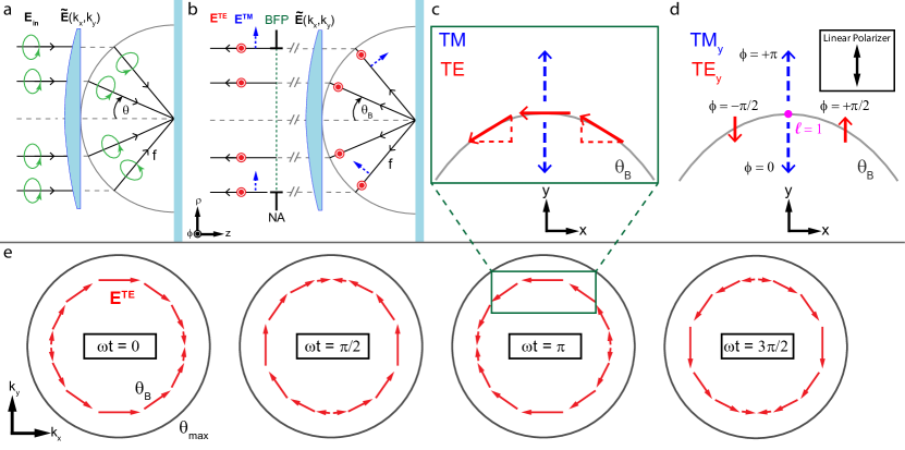
The lens establishes a link between real-space distribution of the paraxial input beam in the BFP and the angular distribution of the focal field . The transformation it performs may be illustrated by a reference sphere of radius around the geometrical focus, to which the beam effectively travels undisturbed. A ray impinging on this reference sphere at a distance from the optical axis is refracted such that it propagates towards the geometrical focus under the divergence angle , corresponding to a coordinate transformation of the form Novotny and Hecht (2012). The process is schematically illustrated for the case of incident CP in Fig. 1a, whereby upon focusing the polarization is preserved for each wave-vector. Since in our case we consider the BFP in reflection, the lens also performs the back-transformation on the reflected field (cf. Fig. 1b). For deriving the latter, it is convenient to employ the TE/TM polarization basis, with the electric field vector being orthogonal () or parallel () to the plane of incidence, respectively. In our cylindrically symmetric focusing system, TE/TM are aligned with the azimuthal and radial unit vectors /. Consequently, in this basis, the reflected field differs from the incident one only by the factor of the Fresnel reflection coefficients Novotny and Hecht (2012):
| (2) |
In the case of a dielectric interface, the reflected TM polarized field vanishes at Brewster’s angle , having peculiar consequences for incident CP light (), as discussed below.
The polarization unit vectors for CP may be written as a phase-delayed superposition of Cartesian unit vectors with , where upper and lower sign correspond to left- and right-hand CP (LCP/RCP), respectively. When switching from the circular () to the cylindrical () basis, the transformation of unit vectors results in for the azimuthal TE polarized field component, i.e. a helical phase profile emerges Bliokh et al. (2011). In consequence, the reflected TE polarized field is an azimuthally polarized vectorial vortex beam with a phase singularity of topological charge on the optical axis. As mentioned, at the TM polarized field vanishes () and therefore the purely TE polarized vectorial vortex beam with phase singularity is naturally separated at Brewster’s angle. Fig. 1e schematically depicts the time evolution of the polarization distribution in the BFP for this azimuthal vortex beam, clearly showing the presence of singularities and elucidating the origin of a central phase vortex.
Moreover, analysis typically employed in polarization microscopy consists of a projection of the reflected beam onto the Cartesian polarization basis. Remarkably, this results in two phase vortices of charge , emerging at the respective intersection points of Cartesian axis and Brewster ring. The effect originates from the polarizing properties of the Fresnel reflection coefficients and may be understood intuitively by investigating a snapshot in time of the polarization distribution around one of these points (cf. Fig. 1c). The coefficient exhibits a zero crossing at Brewster’s angle, which translates to a phase difference of for the radial TM polarized field below and above . At the same time, the phase of the azimuthal TE component remains unaltered by . Projecting the polarization components on the corresponding Cartesian polarization axes results in the field distribution schematically depicted in Fig. 1d. The linear projections of the azimuthal components on opposite sides of the intersection point are out of phase. Together with the inherent phase delay of TE with respect to TM in CP light, a helical phase front forms around the intersection point, i.e. an optical vortex of charge . As a consequence, phase singularities naturally emerge in reflection in any polarization microscopy setup employing high NA.
III Setup
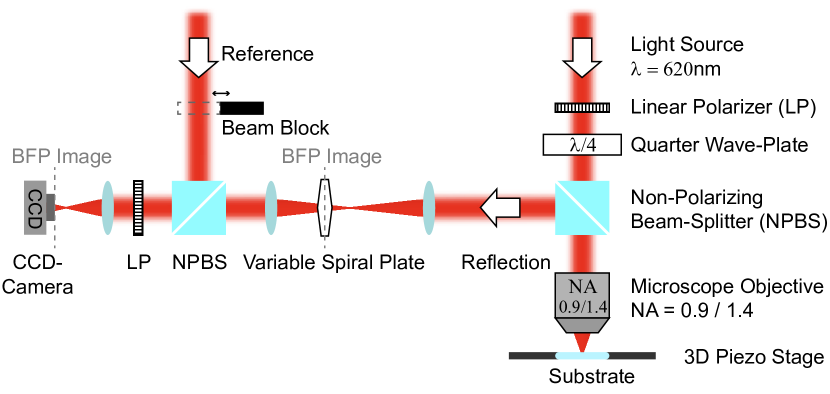
To demonstrate the emergence of a vectorial vortex beam with phase singularity in reflection at Brewster’s angle, we experimentally measure the polarization state and the wavefront of the reflected light in the cylindrical polarization basis. The setup is schematically depicted in Fig. 2.
We focus a CP Gaussian beam with a wavelength of nm onto a BK7 glass substrate. The beam is focused tightly by a dry microscope objective of () or an index-matched oil immersion microscope objective of (). To decompose the reflected beam into its TE/TM components, we first image the objective’s BFP onto a liquid-crystal-based variable spiral plate Slussarenko et al. (2011), which allows for the generation of radial or azimuthal polarization patterns from incident linear polarization states and vice versa Cardano et al. (2012). Consequently, the variable spiral plate enables us to convert the radial and azimuthal TE/TM field components resulting from reflection at the planar substrate to the linear X/Y laboratory axes, with a subsequent projection utilizing a rotatable linear polarizer. It is crucial to note here that, following the geometric considerations presented in Sec. II, at only a purely azimuthally (TE) polarized vectorial vortex beam is reflected, which bears a phase singularity of topological charge . The emerging vortex beam may be separated e.g. by a suitable ring aperture in the BFP.
For measuring the direct projection of the reflected field on the Cartesian X/Y polarization axes we simply remove the variable spiral plate. Furthermore, interferometric measurements are performed by superposition with a reference beam possessing a planar wave front. The phase profile is successively retrieved from the recorded fringe patterns, following the procedure described by Takeda et al. Takeda et al. (1982).
IV Results and Discussion
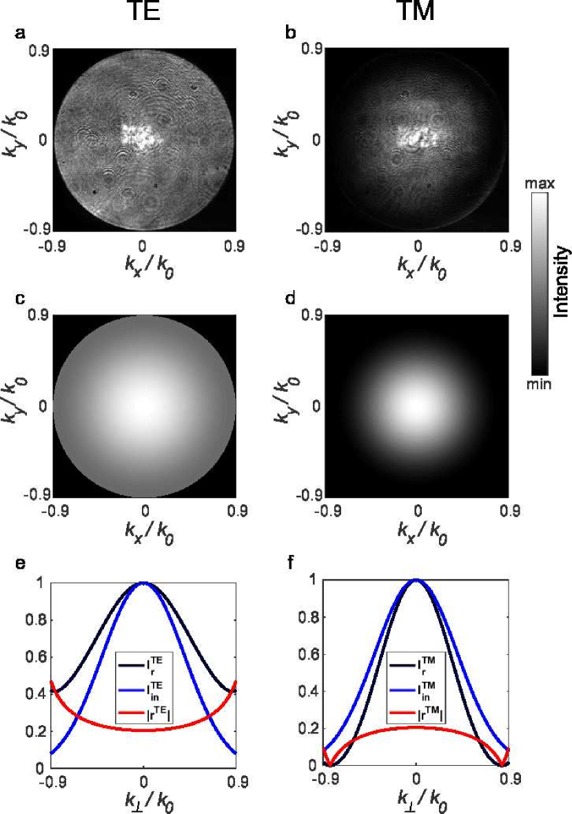
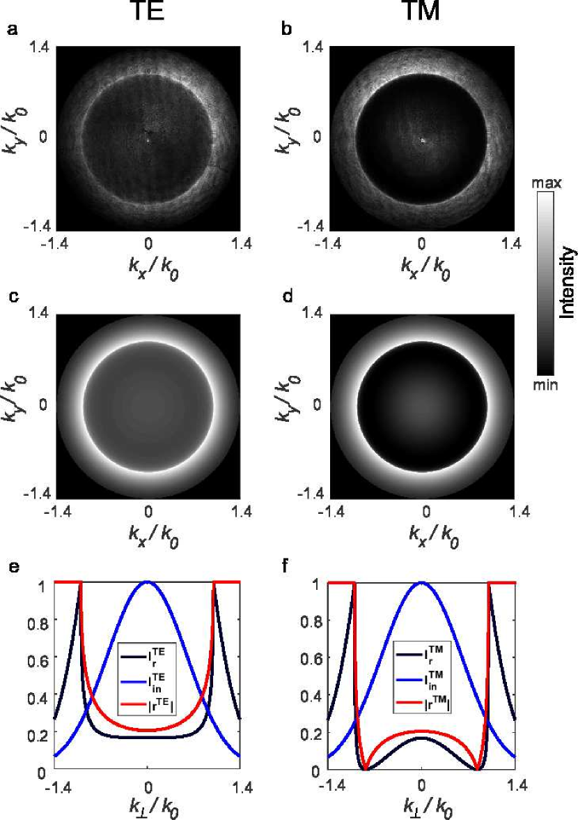
The theoretically calculated and experimentally recorded intensity distributions of TE/TM polarized light in the reflection BFP of the microscope objective are depicted in Fig. 3a-d. In contrast to the TE polarized intensity, TM polarized light exhibits a prominent dark ring towards the outer edges of the BFP López-Morales et al. (2017). The different patterns originate from the distinct angular dependence of the Fresnel reflection coefficients , elucidated in the cross-sectional view of the incident and reflected beam’s intensity alongside with the evolution of in Fig. 3e,f. Since exhibits a zero crossing at Brewster’s angle , a null intensity ring with corresponding radius appears in the BFP.
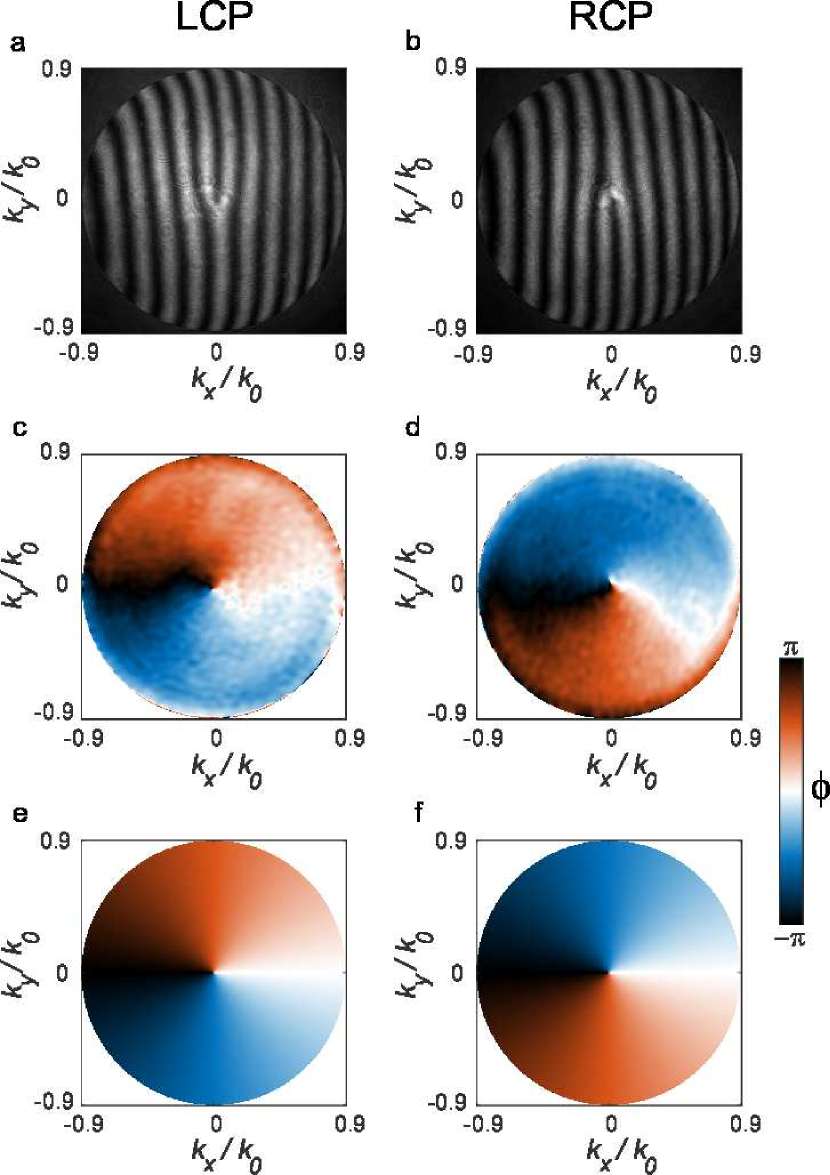
When now interfering the TE polarized field with a planar phase front reference beam, a ’fork’ hologram with opposite orientation for incident LCP/RCP appears (cf. Fig. 4a,b), confirming the presence of a phase vortex with topological charge . The corresponding reconstructed experimental and theoretical phases are shown in Fig. 5c,d and e,f, respectively. The phase images validate the natural emergence of a vectorial vortex beam with central phase singularity in the surprisingly common configuration of focused CP light, reflected from a dielectric substrate at Brewster’s angle .
A frequently applied scheme in polarization microscopy utilizes index-matched immersion oil in the focusing path for investigation of specimens on a substrate in a homogeneous environment. Since Brewster’s angle also appears for the transition to an optically denser medium, e.g. glass to air, similar effects are observed in this measurement scheme. We present corresponding results in Fig. 5, using an index-matched oil immersion type objective of . We benefit from this scheme not only by a broader range of incidence angles, but also by total internal reflection above the critical angle , which due to its vicinity to increases the visibility of the dark ring at Brewster’s angle for TM polarization. The theoretical and experimental intensity distributions for TE/TM nicely reproduce the expected features. Apart from the dark Brewster ring in the TM projection of the BFP, the sharp transition at the critical angle as well as the high intensity above it is evident for both polarizations.
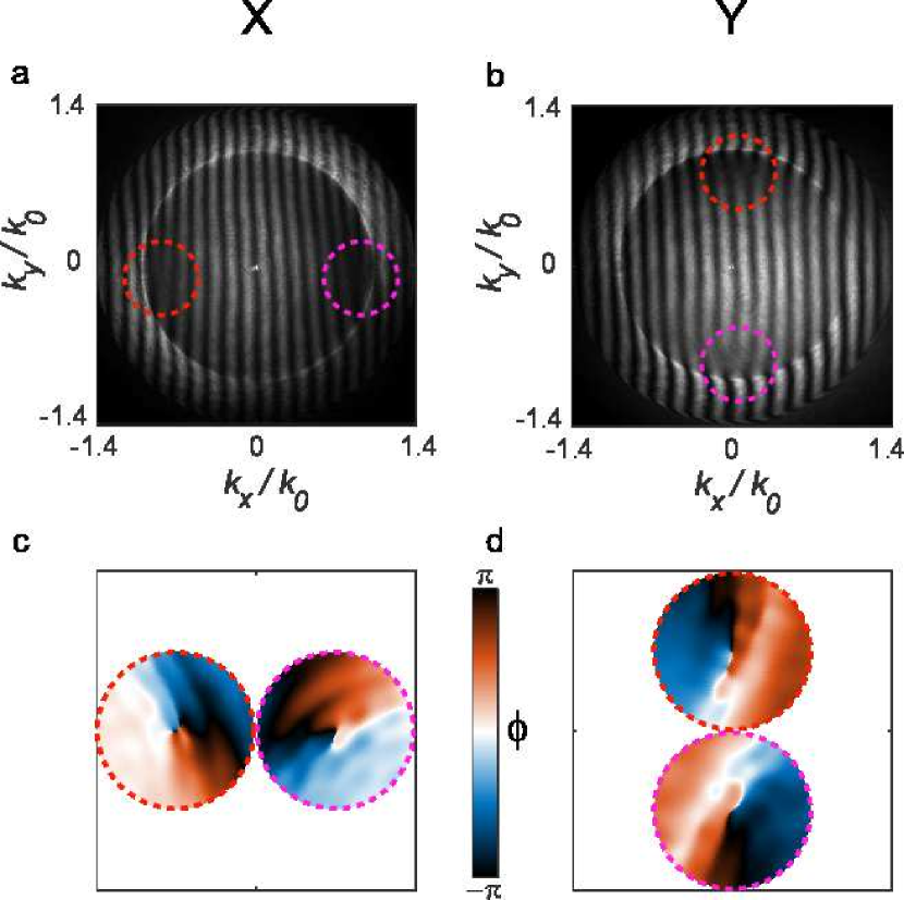
In the next step, we show that the Brewster effect leads to the emergence of phase vortices even in the ubiquitous case of a polarization projection onto Cartesian axes. Therefore, we remove the variable spiral plate (cf. Fig. 2), resulting in a projection of the reflected beam onto Cartesian X/Y instead of cylindrical TE/TM coordinates with the final linear polarizer. As discussed in Sec. II, for a projection of the BFP polarization distribution onto X/Y, we expect two phase vortices forming at the intersection points of the Brewster ring and the respective Cartesian axis. Indeed, the interference patterns for incident RCP in Fig. 6a,b clearly show the emergence of two horizontally or vertically aligned forks at , depending on the Cartesian axis chosen for projection. Likewise, phase reconstruction around both points corroborates the expectation of vortices of topological charge , as shown in the helical phase profiles in Fig. 6c,d. As a result, the presence of these parasitic phase singularities must be considered for any linear polarization projection in reflection from focusing geometries covering Brewster’s angle.
V Conclusion
In conclusion, we experimentally demonstrated the inevitable emergence of phase singularities and generation of vectorial vortices upon reflection of focused CP light from a dielectric substrate under Brewster’s angle. Specifically, we utilized a variable spiral plate to separate the TE and TM polarized field components of the reflected CP Gaussian input beam and directly demonstrated the emergence of an azimuthally polarized vectorial vortex beam with a phase singularity, appearing at Brewster’s angle. Additionally, we performed interferometry in reflection to directly reconstruct the phase profile in the BFP. Moreover, we also demonstrated and interpreted the presence of phase singularities for an even simpler measurement scheme, performing a polarization projection of the reflected field distribution in the BFP onto Cartesian axes.
The utilized experimental scheme is so common, especially in the field of polarization microscopy, that our findings have to be considered widely wherever high focusing geometries for phase and polarization sensitive measurements in reflection are employed. Furthermore, our studies provide an experimentally and conceptually straightforward basis for generation of vectorial vortex beams with a phase singularity, which are of great interest in a broad range of applications utilizing exotic states of light.
Acknowledgements.
The authors gratefully acknowledge inspiring and fruitful discussions with Paweł Woźniak, Martin Neugebauer and Andrea Aiello.References
- Born and Wolf (2013) M. Born and E. Wolf, Principles of optics: electromagnetic theory of propagation, interference and diffraction of light (Elsevier, 2013).
- Rubinsztein-Dunlop et al. (2017) H. Rubinsztein-Dunlop, A. Forbes, M. V. Berry, M. R. Dennis, D. L. Andrews, M. Mansuripur, C. Denz, C. Alpmann, P. Banzer, T. Bauer, E. Karimi, L. Marrucci, M. Padgett, M. Ritsch-Marte, N. M. Litchinitser, N. P. Bigelow, C. Rosales-Guzmán, A. Belmonte, J. P. Torres, T. W. Neely, M. Baker, R. Gordon, A. B. Stilgoe, J. Romero, A. G. White, R. Fickler, A. E. Willner, G. Xie, B. McMorran, and A. M. Weiner, Journal of Optics 19, 013001 (2017).
- Zhan (2009) Q. Zhan, Advances in Optics and Photonics 1, 1 (2009).
- Zhan and Leger (2002) Q. Zhan and J. R. Leger, Optics Express 10, 324 (2002).
- Niziev and Nesterov (1999) V. G. Niziev and A. V. Nesterov, Journal of Physics D: Applied Physics 32, 1455 (1999).
- Dorn et al. (2003) R. Dorn, S. Quabis, and G. Leuchs, Phys. Rev. Lett. 91, 233901 (2003).
- Neugebauer et al. (2016) M. Neugebauer, P. Woźniak, A. Bag, G. Leuchs, and P. Banzer, Nature Communications 7, 11286 (2016).
- Bag et al. (2018) A. Bag, M. Neugebauer, P. Woźniak, G. Leuchs, and P. Banzer, Phys. Rev. Lett. 121, 193902 (2018).
- Allen et al. (1992) L. Allen, M. W. Beijersbergen, R. J. C. Spreeuw, and J. P. Woerdman, Physical Review A 45, 8185 (1992).
- O’Neil et al. (2002) A. T. O’Neil, I. MacVicar, L. Allen, and M. J. Padgett, Phys. Rev. Lett. 88, 053601 (2002).
- Yao and Padgett (2011) A. M. Yao and M. J. Padgett, Advances in Optics and Photonics 3, 161 (2011).
- Bliokh et al. (2010) K. Y. Bliokh, M. A. Alonso, E. A. Ostrovskaya, and A. Aiello, Physical Review A 82, 063825 (2010).
- Bliokh and Nori (2015) K. Y. Bliokh and F. Nori, Physics Reports 592, 1 (2015), transverse and longitudinal angular momenta of light.
- Franke-Arnold et al. (2008) S. Franke-Arnold, L. Allen, and M. Padgett, Laser & Photonics Reviews 2, 299 (2008).
- Bliokh et al. (2015) K. Y. Bliokh, F. J. Rodríguez-Fortuño, F. Nori, and A. V. Zayats, Nature Photonics 9, 796 (2015).
- He et al. (1995) H. He, M. E. J. Friese, N. R. Heckenberg, and H. Rubinsztein-Dunlop, Physical Review Letters 75, 826 (1995).
- Stütz et al. (2007) M. Stütz, S. Gröblacher, T. Jennewein, and A. Zeilinger, Applied Physics Letters 90, 261114 (2007).
- Hell (2003) S. W. Hell, Nature biotechnology 21, 1347 (2003).
- Biener et al. (2002) G. Biener, A. Niv, V. Kleiner, and E. Hasman, Optics Letters 27, 1875 (2002).
- Bomzon et al. (2002) Z. Bomzon, G. Biener, V. Kleiner, and E. Hasman, Optics Letters 27, 1141 (2002).
- Bliokh et al. (2011) K. Y. Bliokh, E. A. Ostrovskaya, M. A. Alonso, O. G. Rodríguez-Herrera, D. Lara, and C. Dainty, Optics express 19, 26132 (2011).
- Marrucci et al. (2006) L. Marrucci, C. Manzo, and D. Paparo, Physical Review Letters 96, 163905 (2006).
- Marrucci et al. (2011) L. Marrucci, E. Karimi, S. Slussarenko, B. Piccirillo, E. Santamato, E. Nagali, and F. Sciarrino, Journal of Optics 13, 064001 (2011).
- Brasselet et al. (2009a) E. Brasselet, N. Murazawa, H. Misawa, and S. Juodkazis, Physical Review Letters 103, 103903 (2009a).
- Gorodetski et al. (2010) Y. Gorodetski, S. Nechayev, V. Kleiner, and E. Hasman, Physical Review B 82, 125433 (2010).
- Karimi et al. (2014) E. Karimi, S. A. Schulz, I. De Leon, H. Qassim, J. Upham, and R. W. Boyd, Light: Science & Applications 3, e167 (2014).
- Garoli et al. (2016) D. Garoli, P. Zilio, Y. Gorodetski, F. Tantussi, and F. De Angelis, Scientific reports 6, 29547 (2016).
- Shitrit et al. (2013) N. Shitrit, I. Yulevich, E. Maguid, D. Ozeri, D. Veksler, V. Kleiner, and E. Hasman, Science 340, 724 (2013).
- Lin et al. (2013) J. Lin, J. P. B. Mueller, Q. Wang, G. Yuan, N. Antoniou, X.-C. Yuan, and F. Capasso, Science 340, 331 (2013).
- Ciattoni et al. (2003a) A. Ciattoni, G. Cincotti, and C. Palma, Phys. Rev. E 67, 036618 (2003a).
- Ciattoni et al. (2003b) A. Ciattoni, G. Cincotti, and C. Palma, J. Opt. Soc. Am. A 20, 163 (2003b).
- Volyar et al. (2006) A. Volyar, V. Shvedov, T. Fadeyeva, A. S. Desyatnikov, D. N. Neshev, W. Krolikowski, and Y. S. Kivshar, Opt. Express 14, 3724 (2006).
- Brasselet et al. (2009b) E. Brasselet, Y. Izdebskaya, V. Shvedov, A. S. Desyatnikov, W. Krolikowski, and Y. S. Kivshar, Opt. Lett. 34, 1021 (2009b).
- Fink (1979) D. Fink, Applied optics 18, 581 (1979).
- Bisson et al. (2006) J.-F. Bisson, J. Li, K. Ueda, and Y. Senatsky, Optics Express 14, 3304 (2006).
- Mansuripur et al. (2011) M. Mansuripur, A. R. Zakharian, and E. M. Wright, Physical Review A 84, 033813 (2011).
- Kobayashi et al. (2012) H. Kobayashi, K. Nonaka, and M. Kitano, Opt. Express 20, 14064 (2012).
- Bouchard et al. (2014) F. Bouchard, H. Mand, M. Mirhosseini, E. Karimi, and R. W. Boyd, New Journal of Physics 16, 123006 (2014).
- Aleksanyan and Brasselet (2016) A. Aleksanyan and E. Brasselet, Optica 3, 167 (2016).
- Radwell et al. (2016) N. Radwell, R. Hawley, J. B. Götte, and S. Franke-Arnold, Nature Communications 7, 10564 (2016).
- Zhao et al. (2007) Y. Zhao, J. S. Edgar, G. D. M. Jeffries, D. McGloin, and D. T. Chiu, Physical Review Letters 99, 073901 (2007).
- Fernandez-Corbaton et al. (2012) I. Fernandez-Corbaton, X. Zambrana-Puyalto, and G. Molina-Terriza, Physical Review A 86, 042103 (2012).
- Fernandez-Corbaton et al. (2013) I. Fernandez-Corbaton, X. Zambrana-Puyalto, N. Tischler, X. Vidal, M. L. Juan, and G. Molina-Terriza, Physical Review Letters 111, 060401 (2013).
- Novotny et al. (2001) L. Novotny, R. D. Grober, and K. Karrai, Opt. Lett. 26, 789 (2001).
- Nasalski (2001) W. Nasalski, Optics Communications 197, 217 (2001).
- Nasalski (2006) W. Nasalski, Phys. Rev. E 74, 056613 (2006).
- Nasalski and Pagani (2006) W. Nasalski and Y. Pagani, Journal of Optics A: Pure and Applied Optics 8, 21 (2006).
- Yavorsky and Brasselet (2012) M. Yavorsky and E. Brasselet, Opt. Lett. 37, 3810 (2012).
- Brewster (1815) D. Brewster, Proceedings of the Royal Society of London Series I 2, 14 (1815).
- Paniagua-Domínguez et al. (2016) R. Paniagua-Domínguez, Y. F. Yu, A. E. Miroshnichenko, L. A. Krivitsky, Y. H. Fu, V. Valuckas, L. Gonzaga, Y. T. Toh, A. Y. S. Kay, B. Luk’yanchuk, et al., Nature Communications 7, 10362 (2016).
- Luo et al. (2011) H. Luo, X. Zhou, W. Shu, S. Wen, and D. Fan, Physical Review A 84, 043806 (2011).
- Kong et al. (2012) L.-J. Kong, X.-L. Wang, S.-M. Li, Y. Li, J. Chen, B. Gu, and H.-T. Wang, Applied Physics Letters 100, 071109 (2012).
- Aiello et al. (2009) A. Aiello, M. Merano, and J. P. Woerdman, Optics Letters 34, 1207 (2009).
- Empedocles et al. (1999) S. A. Empedocles, R. Neuhauser, and M. G. Bawendi, Nature 399, 126 (1999).
- Sönnichsen and Alivisatos (2005) C. Sönnichsen and A. P. Alivisatos, Nano letters 5, 301 (2005).
- Whittaker et al. (1994) P. Whittaker, R. A. Kloner, D. R. Boughner, and J. G. Pickering, Basic research in cardiology 89, 397 (1994).
- Novotny and Hecht (2012) L. Novotny and B. Hecht, Principles of Nano-Optics (Cambridge University Press, Cambridge, 2012).
- Slussarenko et al. (2011) S. Slussarenko, A. Murauski, T. Du, V. Chigrinov, L. Marrucci, and E. Santamato, Opt. Express 19, 4085 (2011).
- Cardano et al. (2012) F. Cardano, E. Karimi, S. Slussarenko, L. Marrucci, C. de Lisio, and E. Santamato, Appl. Opt. 51, C1 (2012).
- Takeda et al. (1982) M. Takeda, H. Ina, and S. Kobayashi, J. Opt. Soc. Am. 72, 156 (1982).
- López-Morales et al. (2017) G. López-Morales, V.-M. Rico-Botero, R. Espinosa-Luna, and Q. Zhan, Chin. Opt. Lett. 15, 030004 (2017).