Joint Power Splitting and Relay Selection in Energy-Harvesting Communications for IoT Networks
Abstract
In this paper, we consider an energy-harvesting (EH) relay system consisting of a source, a destination, and multiple EH decode-and-forward (DF) relays that can harvest the energy from their received radio signals. A power-splitting ratio is employed at an EH DF relay to characterize a trade-off between the energy used for decoding the source signal received at the relay and the remaining energy harvested for retransmitting the decode outcome. We propose an optimal power splitting based relay selection (OPS-RS) framework and also consider the conventional equal power splitting based relay selection (EPS-RS) for comparison purposes. We derive closed-form expressions of outage probability for both the OPS-RS and EPS-RS schemes and characterize their diversity gains through an asymptotic outage analysis in the high signal-to-noise ratio region. We further examine an extension of our OPS-RS framework to an energy-harvesting battery (EHB) enabled cooperative relay scenario, where the EH relays are equipped with batteries used to store their harvested energies. We propose an amplify-and-forward (AF) based EHB-OPS-RS and a DF based EHB-OPS-RS schemes for AF and DF relay networks, respectively. Numerical results show that the proposed OPS-RS always outperforms the EPS-RS in terms of outage probability. Moreover, the outage probabilities of AF and DF based EHB-OPS-RS schemes are much smaller than that of OPS-RS and EPS-RS methods, demonstrating the benefit of exploiting the batteries in EH relays. Additionally, the DF based EHB-OPS-RS substantially outperforms the AF based EHB-OPS-RS and such an outage advantage becomes more significant, as the number of EH relays increases.
Index Terms:
Energy harvesting, power splitting, relay selection, outage probability, diversity gain.I Introduction
Wireless cooperative communications has attracted tremendous research attention in recent years [1]-[5], where a user terminal first transmits a source signal to a cooperative partner which then relays its received signal to the desired destination. As shown in [6] and [7], there are two basic relaying protocols, namely the amplify-and-forward (AF) and decode-and-forward (DF). Generally, AF allows the relay to simply retransmit a scaled version of its received noisy signal without any sort of decoding, which has an advantage of simple implementation, but suffers from a noise propagation issue. By contrast, in the DF protocol, the relay needs to decode the noisy source signal first and retransmits its correctly decoded outcome to the destination, which can alleviate the noise propagation problem at the cost of computational complexity and latency. It is generally recognized that cooperative relay communications relying on either AF or DF is capable of improving the network coverage and transmission reliability in wireless fading environments [8].
Considering multiple relays available in wireless networks, one may exploit all of them to simultaneously forward their received source signals over a single channel with the aid of beamforming, also termed as cooperative relay beamforming [9]-[11]. Although such cooperative beamforming technique can significantly improve the wireless throughput, it requires complex symbol-level relay synchronization for the sake of mitigating inter-symbol interference among spatially distributed relays. Alternatively, multiple relays may be considered to retransmit their received source signals over orthogonal channels to avoid the complex relay synchronization [12]-[14], which however sacrifices multiplexing gain and reduces spectral utilization, since more orthogonal channel resources are consumed with an increasing number of relays. To this end, opportunistic relay selection as a promising means of efficiently utilizing multiple relays has been studied extensively in literature [15]-[17], where the single best relay is chosen to retransmit the source signal and thus only one orthogonal channel is required for the best-relay retransmission regardless of the number of relays. It has been shown in [15]-[17] that the best-relay selection approach can achieve the same full diversity as the aforementioned cooperative relay methods [10]-[14].
Typically, wireless terminals are powered by rechargeable batteries with limited energy capacity. As an alternative, energy harvesting (EH) is emerging as an effective means of enabling wireless devices to capture energy from their surrounding environments, such as the solar energy, wind energy, and radio frequency (RF) energy, which is attractive to machine-to-machine (M2M) communications [18]-[20] in IoT networks [21]-[25], since IoT sensors and devices are generally powered by energy-limited batteries without constant power supply. In [26], simultaneous wireless information and power transfer (SWIPT) was investigated and two SWIPT protocols were proposed, namely the time-switching (TS) and power-splitting (PS) protocols. To be specific, the PS protocol considers the use of a power splitter to separate a received RF signal into two parts for the energy harvesting and signal decoding, respectively. By contrast, in the TS protocol, the received RF signal is divided into two components in time domain [27]. Moreover, the authors of [28] studied the impact of a nonlinear energy harvesting model on the achievable rate region of RF-powered two-way communication systems.
I-A Related Works and Motivation
Recently, an increasing research attention has been paid to the combination of EH with cooperative relays [29]-[35]. More specifically, in [29], a tradeoff between the energy relaying (ER) and information relaying (IR) was investigated for the sake of maximizing the delay-limited throughput of RF powered wireless networks. The authors of [30] studied wireless transmissions with the help of a single EH relay and derived a closed-form outage probability expression for the EH relay aided cooperative transmissions over Rayleigh fading channels. Later on, in [31], an interior point penalty function based EH relay selection algorithm was presented for a multiple EH relay network. In [32], the authors derived closed-form outage probability expressions of relay selection for cooperative EH DF relay networks with a fixed power splitting factor. Differing from the DF protocol used in [32], the authors of [33] and [34] considered the AF strategy for EH relays and proposed various EH relay selection schemes to improve the outage performance of EH AF relay networks. Additionally, an extension of the EH relay selection to multi-antenna multi-relay systems was investigated in [35], where a joint relay-and-antenna selection scheme is proposed to enhance the transmission throughput and reduce the outage probability.
In addition to the aforementioned EH relay selection work [29]-[35], there are also some research efforts devoted to exploring power allocation for energy-harvesting relay systems [36]-[39]. For example, in [36], the authors studied the power allocation for a cooperative DF relay network in which the source node is assumed to have a limited energy storage and can harvest power from its surrounding RF signals. The authors of [37] considered a cooperative EH relay network consisting of multiple source-destination pairs with the assistance of an EH relay and an auction based power allocation scheme was proposed to address the harvested energy distribution among the multiple source nodes. Moreover, in [38], dynamic programming was exploited for the optimal power allocation of wireless EH communications in terms of minimizing the outage probability. Besides, the authors of [39] considered an EH relay network consisting of a source, an EH relay and a destination, where the source transmits its confidential information to the relay, while the destination sends an interference signal to prevent the relay from decoding the source message. The optimal power allocation between the source and destination was investigated to maximize the secrecy rate of source-destination transmissions.
It needs to be pointed out that the aforementioned efforts [29]-[39] have separately investigated either the relay selection or power allocation for EH relay systems. Presently, only a few research attention has been paid to the joint relay selection and resource allocation for EH cooperative networks [40], [41]. Specifically, in [40], the authors formulated a sum-rate maximization problem under the constraints of total transmit power and harvested energy for a two-way AF relay network, for which an optimal resource allocation and relay selection scheme is proposed. Moreover, the geometric programming and binary particle swarm optimization were exploited in [41] to address the joint optimization of relay selection and power splitting for an EH-based two-way AF relaying system. Different from the AF protocol considered in [40] and [41], we explore the joint power splitting and relay selection for a cooperative EH DF relay network consisting of a source, a destination, and multiple DF relays that are capable of harvesting energies from their surrounding RF environments. A power splitter is assumed at each EH relay to divide its received RF signal into two separate parts for the information decoding and relaying, respectively, where a power-splitting ratio (PSR) is defined as the ratio of an harvested energy for the information relaying to the total RF energy received at the relay.
The main contributions of this paper can be summarized as follows. First, we propose an optimal power splitting based relay selection (OPS-RS) framework for cooperative EH DF relay systems, which is different from [40] and [41], where the AF protocol was considered for the joint power splitting and relay selection design. This also differs from [32] where only the relay selection was studied for EH DF relay networks without the optimization of power splitting. Typically, a higher PSR means that more harvested energy is used to transmit the decoded outcome of a source signal, which, however, results in less energy left at a DF relay to decode the source signal along with more decoding errors occurred, implying a tradeoff between the transmission energy and decoding energy. Second, we derive closed-form expressions of the outage probability for both the proposed OPS-RS and conventional equal power splitting based relay selection (EPS-RS). Third, the diversity gains of both OPS-RS and EPS-RS are characterized through an asymptotic outage probability analysis in the high signal-to-noise ratio (SNR) region. Finally, we examine an extension of our OPS-RS framework to an energy-harvesting battery (EHB) enabled cooperative relay scenario, and propose an AF based EHB-OPS-RS and a DF based EHB-OPS-RS schemes for AF and DF relay networks, respectively.
The rest of this paper is organized as follows. In Section II, we describe the system model of a cooperative EH relay network. Section III presents the OPS-RS and EPS-RS as well as their outage probability analysis. In Section IV, the diversity analysis of OPS-RS and EPS-RS is carried out. Next, an extension of our OPS-RS framework to an EHB enabled cooperative relay scenario is considered in Section V, where an AF and a DF based EHB-OPS-RS schemes are proposed for AF and DF relay networks, respectively. Section VI provides some numerical outage probability results of the OPS-RS, EPS-RS as well as the AF and DF based EHB-OPS-RS schemes. Finally, Section VII gives some concluding remarks.
II System Model
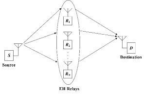
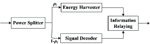
As shown in Fig. 1, we consider an EH relay system consisting of a source (), a destination () and separate EH relay nodes denoted by , each equipped with a single antenna, where the destination is out of the transmit coverage of source node and an EH relay is opportunistically chosen to assist the source-destination transmission. Notice that all the relays are assumed to harvest energies from their received source signals without stable power supply. Moreover, the EH relays can be either dedicated nodes deployed for helping the source transmit to the destination or peer nodes that assist the source-destination transmission and obtain incentives in terms of energy and spectrum resources. Fig. 2 shows a block diagram for an EH relay , where a received source signal is first divided with a power splitter (PS) into two separate parts, which are respectively fed to the signal decoder for decoding the source message and the energy harvester for supplying the power of subsequent information relaying module. It can be observed that compared to the TS strategy, the PS protocol consumes no extra time resources, which is thus used throughout this paper. Although only the PS protocol is considered, similar performance analysis and results could be obtained for the TS protocol.
Without loss of generality, let and denote the transmit power and data rate of source node, respectively. The PSR of EH relay is represented by (), which is defined as the ratio of the energy harvested for the information relaying to the total energy received at the relay . The remaining fraction of the total received energy is used for the information decoder. Moreover, fading coefficients of the channel from the source to EH relay and that from to destination are denoted by and , respectively. In addition, a zero-mean additive white Gaussian noise (AWGN) with a variance of is assumed at any receiver of Fig. 1.
Following the existing literature on EH communications (e.g., [26], [32]-[34]), the Rayleigh fading is used to model the fading coefficients of and . Although the Rayleigh fading is used in this paper, similar outage probability analysis can be obtained for other fading models (e.g. Rician fading) by simply modeling and with the corresponding probability density function instead (e.g., Rician distribution). Accordingly, one can readily obtain that and follow exponential distributions, whose probability distribution functions can be expressed as
| (1) |
and
| (2) |
where and are the means of random variables and , respectively.
Considering that the source node broadcasts its signal () with a transmit power of to the EH relays, we can express the signal received at an EH relay as
| (3) |
where is a zero-mean additive white Gaussian noise (AWGN) with a variance of encountered at the EH relay . As aforementioned, the relay first divides its received signal with a power splitter into two separate components for the information decoder and energy harvester, respectively. To be specific, a fraction of the total received energy is allocated for the energy harvester to supply the power of information relaying module and the remaining fraction is used for the information decoder to decode the source message. As a consequence, the energy collected at the energy harvester of relay can be obtained from (3) as
| (4) |
where is a conversion efficiency of the energy harvester and represents the duration of a time slot. Following the existing literature on EH communications [26]-[41], we consider the use of a linear EH model with the perfect channel state information (CSI) available, as given by (4). Although a non-linear EH model proposed in [42] is more general in practice, it is analytically untractable as discussed in [43]. To this end, the linear EH model is often assumed along with the perfect CSI available for the purpose of tractability, which has been widely adopted in the existing literature [26]-[41] and [43]. It is indeed interesting to explore an extension to a general scenario with CSI errors and nonlinear EH model, which is out of the scope of this paper and considered for future work. Hence, the transmit power used in the information relaying module of relay during the following time slot with a duration of can be expressed as
| (5) |
As mentioned above, the relay utilizes the remaining fraction of the total received energy for decoding the source message . Noting that the remaining part of the received signal is directly employed for decoding without the energy conversion, we thus express the received signal power for information decoder at the relay as
| (6) |
from which the received signal-to-noise ratio (SNR) at the relay is obtained as
| (7) |
where . From (7), the channel capacity from the source to relay can be given by
| (8) |
Next, among the EH relays, an EH relay that succeeds in decoding the source message is opportunistically chosen to forward its decode result in another time slot. Without loss of generality, let us consider that the EH relay succeeding in decoding is selected to forward the source message to the destination with a transmit power of as given by (5). Thus, the corresponding received signal at the destination is written as
| (9) |
where is a zero-mean AWGN with a variance of encountered at the destination. From (9), we can readily obtain the received SNR at the destination as
| (10) |
from which the channel capacity from the relay and destination is given by
| (11) |
Following existing literature on DF relaying transmissions [1]-[3], an overall channel capacity from the source to destination via a relay is given by the minimum of the channel capacity from source to relay and that from relay to destination. Hence, using (8) and (11), the overall channel capacity from the source via an EH relay to destination can be expressed as
| (12) |
which completes the system model of EH relay transmissions with the DF protocol.
III Joint Power Splitting and Relay Selection
In this section, we first propose the OPS-RS scheme for cooperative EH relay networks. For comparison purposes, the traditional EPS-RS is also considered as a baseline. Closed-form outage probability expressions are derived for the EPS-RS and OPS-RS schemes over Rayleigh fading channels.
III-A EPS-RS Scheme
This subsection presents the conventional EPS-RS scheme as a benchmark. As aforementioned, the source first transmits its signal to the EH relays which then divide their received radio signals with a power-splitter into two separate components for the energy harvester and information decoder, respectively. As implied in the name, the EPS-RS scheme allows an EH relay to divide the total energy of its received signal into two equal parts, i.e., the PSR of each EH relay is given by for the EPS-RS scheme. In other words, one half of the total received power is used for the energy harvester and the remaining power is used for the information decoder. Substituting into (8), we can obtain the channel capacity from the source to EH relay for the EPS-RS scheme as
| (13) |
Similarly, given , the channel capacity from the EH relay to destination for the EPS-RS scheme can be obtained from (11) as
| (14) |
From (12)-(14), we can obtain an overall channel capacity from the source via an EH relay to destination for the EPS-RS scheme as
| (15) |
where and are given by (13) and (14), respectively.
Typically, an EH relay that maximizes the overall channel capacity from the source to destination is opportunistically selected to assist the source-destination transmission. Therefore, from (15), an opportunistic relay selection criterion can be written as
| (16) |
where denotes the best EH relay selected by the EPS-RS scheme. According to (16), the overall channel capacity from the source to destination for the EPS-RS scheme is given by
| (17) |
In what follows, we present an outage probability analysis for the conventional EPS-RS scheme. As is known, an outage event happens when the channel capacity falls below a predefined data rate. Thus, the probability of occurrence of an outage event (also called outage probability) for the conventional EPS-RS scheme is obtained as
| (18) |
where denotes the data rate of source-destination transmissions. Substituting from (17) into (18) and noting that for different relays () are independent of each other, we have
| (19) |
where and . Noting that and are independent exponentially distributed with respective means of and , and denoting and , we can rewrite the term of (19) as
| (20) |
Using the Maclaurin series expansion, we have
| (21) |
for . Combining (20) and (21), we arrive at
which can be expanded to
| (22) |
where is known as the exponential integral function and is given by
Finally, substituting from (22) into (19) yields
| (23) |
which gives a closed-form expression of outage probability for the EPS-RS scheme. It needs to be pointed out that an infinite series is involved in (23) due to the use of Maclaurin series expansion as given by (21), which can be converged quickly after a few iterations of .
III-B OPS-RS Scheme
In this section, we propose the OPS-RS scheme and derive its closed-form outage probability over Rayleigh fading channels. In the proposed OPS-RS scheme, the source first broadcasts its message to EH relays which then perform an optimal power splitting for the sake of maximizing the overall channel capacity from source to destination. Finally, an EH relay with an optimized power splitter that has the highest overall channel capacity is chosen to assist the source transmission to destination. This differs from the conventional EPS-RS approach, where the total energy received at an EH relay is simply divided into two equal parts. Without loss of generality, let us consider that the source transmits its signal to the destination via an EH relay with a PSR . Hence, from (12), an optimal PSR for maximizing the overall channel capacity from source via to destination can be obtained as
| (24) |
where and are given by (8) and (11), respectively. Combining (8), (11) and (24), we can further obtain
| (25) |
It can be observed from (25) that if the term is not equal to , a higher value of can always be obtained by either increasing to increase and decrease or decreasing to increase and decrease , until becomes the same as , since they are an increasing and a decreasing functions of , respectively. Therefore, an optimal PSR can be obtained from (25) as
| (26) |
which, in turn, leads to
| (27) |
Substituting the optimal PSR from (27) into (12), we can obtain an overall channel capacity from the source to destination via EH relay with an optimized power-splitter for the OPS-RS scheme as
| (28) |
In the OPS-RS scheme, an EH relay having the highest overall channel capacity of is chosen to forward the source message to destination. Hence, using (28), we can obtain a relay selection criterion for the OPS-RS scheme as
| (29) |
where denotes the best EH relay selected by the OPS-RS scheme. As shown in (27) and (29), the channel fading amplitudes of and are needed at an EH relay to perform the optimization of PSR and relay selection. It is pointed out that the fading amplitude of may be obtained at the relay through channel estimation. Moreover, the destination can estimate the fading amplitude of and then feed it back to the relay . In addition, a distributed relay selection framework can be implemented at the separate EH relays. More specifically, each EH relay maintains a timer whose initial value is set in inverse proportional to the term as given by (29). In this way, the EH relay with the smallest initial value becomes the best relay node, which exhausts its timer earliest and then broadcasts a control packet to notify the source, destination and other EH relays [15]. From (29), the overall source-destination channel capacity for the OPS-RS scheme is given by
| (30) |
where is given by (28).
The following presents an outage probability analysis for the proposed OPS-RS scheme. As discussed, an outage event occurs when the channel capacity of proposed OPS-RS scheme drops below a predefined data rate . Hence, using (30) and noting that for different relays () are independent of each other, we can obtain an outage probability of the OPS-RS scheme as
| (31) |
Substituting from (28) into (31) gives
| (32) |
which is further simplified to
| (33) |
where . Again, noting that random variables and are independent exponentially distributed with respective means of and , and denoting and , we can rewrite (33) as
| (34) |
which is further given by
| (35) |
where is the first-order modified Bessel function of second kind as given by (8.432.6) in [44]. So far, we have derived closed-form outage probability expressions for both the EPS-RS and OPS-RS schemes over Rayleigh fading channels.
IV Diversity Gain Analysis
In this section, we present an asymptotic outage probability analysis in the high SNR region to characterize diversity gains of the EPS-RS and OPS-RS schemes. Following [45] and [46], the diversity gain is defined as a ratio of the logarithm of an outage probability to the logarithm of SNR as the SNR approaches to infinity, namely
| (36) |
where represents an outage probability as a function of the SNR .
IV-A EPS-RS
This subsection conducts the diversity analysis of traditional EPS-RS scheme. From (36), the diversity gain of EPS-RS scheme can be obtained as
| (37) |
where is given by (19). Substituting from (20) into (19) gives
| (38) |
where and .
Proposition 1: Given an exponential random variable () with a mean of , the following equation holds with one probability
for , where and .
Proof: See Appendix A for details. It is pointed out that the term becomes random due to the presence of an exponential random variable in Proposition 1. Moreover, the expectation of () is given by that tends to infinity for , resulting in an uncertainty of the convergence of the random term , which motivates the proof of Proposition 1.
Using Proposition 1, we can obtain from (38) as
| (39) |
for . Noting and using the Taylor expansion for , we can arrive at
| (40) |
where higher-order infinitesimals are ignored. Combining (39) and (40), we obtain
| (41) |
for . Substituting from (41) into (37), the diversity gain of EPS-RS scheme is given by
| (42) |
which shows that a diversity gain of is achieved by the traditional EPS-RS scheme.
IV-B OPS-RS
In this subsection, we analyze the diversity gain of proposed OPS-RS scheme. From (30), the diversity of OPS-RS scheme can be obtained as
| (43) |
where is given by (35). Noting and letting , we can obtain the term approaching to zero, namely
which, in turn, leads to
| (44) |
Combining (35) and (44), we have
| (45) |
for . Substituting into the preceding equation gives
| (46) |
for . Moreover, using the Taylor expansion and ignoring higher-order infinitesimals, we can obtain
| (47) |
for . Combining (46) and (47), we arrive at
| (48) |
for . Substituting from (48) into (43) yields
| (49) |
from which one can observe that the OPS-RS scheme achieves the diversity gain of , where is the number of EH relays. As a consequence, as the number of EH relays increases, the diversity gain of OPS-RS scheme increases accordingly, demonstrating a significant amount of outage performance improvement achieved through increasing the number of EH relays.
V Extension to EHB Enabled Cooperative Relay Systems
In this section, we are focused on an extension of the aforementioned OPS-RS framework to an EHB enabled cooperative relay scenario, where the EH relays are considered to be equipped with batteries used to store their harvested energies.
V-A DF based EHB-OPS-RS Scheme
This subsection proposes an EHB-OPS-RS scheme for DF relay networks, referred to as the DF based EHB-OPS-RS scheme. Let denote the energy previously harvested and accumulated in the battery of relay , which starts with zero at the very beginning. Moreover, once an EH relay is selected to assist the source-destination transmission, the stored energy in its battery is used to re-transmit the source signal. Denoting the energy currently collected at the energy harvester of relay for the information relaying by , we can express the total energy available for the relay as
| (50) |
where is given by
| (51) |
From (50) and (51), the transmit power available at the EH relay can be expressed as
| (52) |
where represents the power generated from the energy stored at the battery of . Meanwhile, similarly to (6), the remaining fraction of the currently harvested energy at the relay is used for the information decoder and the corresponding power is written as
| (53) |
from which the channel capacity from the source to relay is given by
| (54) |
where . Moreover, by using (52), the channel capacity from the relay to destination is given by
| (55) |
where . Similarly to (24), an optimal PSR for the DF based EHB-OPS-RS scheme can be obtained from (54) and (55) as
| (56) |
which leads to
| (57) |
where . It can be observed that if no batteries are equipped at the EH relays (i.e., ), the optimal PSR of (57) for the DF based EHB-OPS-RS scheme is degraded to that of (27) for the OPS-RS without the battery. Substituting the optimal PSR from (57) into (54) and (55), we can obtain an overall channel capacity from the source via an EH relay to the destination as
| (58) |
One can see from (57) that an optimal PSR of arises given , which means that the stored battery power is sufficiently high for retransmitting the source signal without the need of any additionally harvested energy. In this case, all the currently harvested power as implied from (53) by substituting is used for the information decoder and an extra power of is exhausted from the battery to ensure that the channel capacity from the source to relay is equal to that from the relay to destination for maximizing the overall channel capacity from the source via relay to destination, namely . Therefore, the remaining battery power of relay is obtained as for . Otherwise, when , it means that all the stored battery power would be exhausted for retransmitting the source signal as implied from (56) and (57), and thus the remaining battery power of relay becomes zero for . As a consequence, if the relay is chosen to re-transmit the source signal to the destination, its remaining battery power is given by
| (59) |
where represents the power generated from the maximal energy that can be stored in the battery of an EH relay due to the battery capacity limit. Otherwise, all the currently harvested energy is accumulated in the EHB of relay and the battery power is given by
| (60) |
where is used since the relay is not chosen to assist the source-destination transmission and no decoding process is necessary at in this case, leading to that the total received signal is utilized for energy harvesting.
V-B AF based EHB-OPS-RS Scheme
In this subsection, we consider the AF protocol for the EH relays and propose an AF based EHB-OPS-RS scheme. In the AF strategy, the relay first divides its received source signal as given by (3) into two fractions and , which are used for the energy harvester and information retransmission, respectively. Similarly to (52), the transmit power available at the EH relay is given by
| (61) |
where is the power generated from the energy stored at the battery of . Then, the EH relay forwards the remaining fraction of its received source signal with a scaling factor to the destination at a power of . Thus, the received signal at the destination is written as
| (62) |
from which the corresponding transmit power is given by
| (63) |
Using (61) and (63), we can obtain the scaling factor as
| (64) |
where the second approximated equation is obtained in the high SNR region such that holds with a high probability. Combining (62) and (64) yields the received SNR at the destination as
| (65) |
where the parameter is given by
Substituting from (64) into the preceding equation yields
| (66) |
where and . Hence, an optimal PSR for the AF based EHB-OPS-RS scheme can be obtained for the sake of maximizing the received SNR of (65), namely
| (67) |
which is equivalent to
| (68) |
From (66), the first-order and second-order derivatives of with respect to are obtained as
| (69) |
and
| (70) |
It can be observed from (70) that the second-order derivative is always positive for any in the range of , implying the existence of a unique optimal PSR to maximize the received SNR at the destination. Moreover, the optimal PSR should make the first-order derivative become zero, namely
| (71) |
from which a closed-form solution to the optimal PSR is given by
| (72) |
where , , and . It needs to be pointed out that if no batteries are equipped at the EH relays, namely , the optimal PSR of (72) is degraded to . Moreover, in the AF based EHB-OPS-RS scheme, if the EH relay is selected to assist the source-destination transmission, all the stored energy of its battery is used for forwarding the source signal and the remaining battery power at is given by
| (73) |
Otherwise, all the currently harvested energy is accumulated and the battery power of relay is obtained as
| (74) |
which is used for future possible retransmissions of the source signal. Substituting the optimal PSR from (72) into (65), we can obtain the channel capacity from the source via an EH relay to destination relying on the AF based EHB-OPS-RS scheme as
| (75) |
which completes the AF based EHB-OPS-RS scheme.
VI Numerical Results and Discussions
In this section, we present numerical outage probability results of the EPS-RS and OPS-RS as well as the AF and DF based EHB-OPS-RS schemes. Following the existing literature [26] and [27], the average channel gains of and an energy conversion efficiency of are assumed in our numerical evaluations. Also, an SNR of , a maximal SNR of generated from the battery of an EH relay due to the battery capacity limit, a data rate of , and the number of EH relays are considered, unless otherwise stated. It is pointed out that the AF based EHB-OPS-RS scheme can be regarded as a variation of the AF based joint power splitting and relay selection framework designed in [40] and [41] originally for two-way relay networks.
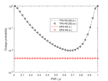
Fig. 3 shows theoretical and simulated outage probabilities versus PSR of the traditional power splitting based relay selection (TPS-RS) [32] and proposed OPS-RS schemes with , bit/s/Hz, , and . In Fig. 3, the PSR of TPS-RS scheme varies in the interval of , while an optimized PSR as given by (27) is utilized in the proposed OPS-RS scheme. It is shown from Fig. 3 that with an increasing PSR, the outage probability of TPS-RS decreases first and then increases, demonstrating that a tradeoff exists between the transmission energy and decoding energy. In other words, a minimized outage probability can be achieved for the TPS-RS scheme through an optimization of the PSR. One can also see from Fig. 3 that even the minimized outage probability of TPS-RS with an optimized PSR is much higher than the outage probability of proposed OPS-RS, showing the outage advantage of our scheme. This is because that the PSR optimization of TPS-RS in terms of minimizing the outage probability only utilizes statistical CSI of and , whereas an instantaneous CSI is employed in the proposed OPS-RS scheme as implied from (27). In addition, the theoretical and simulated outage probability results of Fig. 3 match well with each other, validating our outage probability analysis.
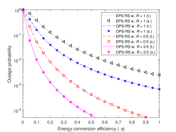
Fig. 4 shows theoretical and simulated outage probabilities versus energy conversion efficiency of the EPS-RS and OPS-RS schemes for different data rates of bit/s/Hz and bit/s/Hz, where the theoretical outage probabilities of EPS-RS and OPS-RS are obtained by using (23) and (35) and their simulated results are given through Monte-Carlo simulations. It is observed from Fig. 4 that the theoretical outage probability curves match well with the corresponding simulation results, further verifying the correctness of closed-form outage analysis. Fig. 4 also shows that as the energy conversion efficiency increases, the outage probabilities of both EPS-RS and OPS-RS decrease accordingly. This is due to the fact that with an increasing , more energies are converted from received RF signals for powering the retransmission of the source message to destination, which leads to a lower outage probability.
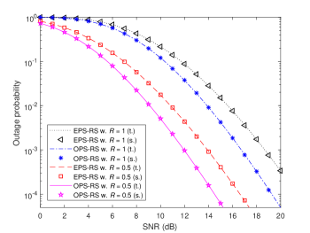
Fig. 5 depicts outage probability versus SNR of the EPS-RS and OPS-RS schemes for different data rates of bit/s/Hz and bit/s/Hz. It can be seen from Fig. 5 that for both cases of bit/s/Hz and bit/s/Hz, the outage probabilities of EPS-RS and OPS-RS decrease with an increase of SNR, and moreover, the OPS-RS scheme always performs better than the EPS-RS scheme in terms of outage probability. Fig. 5 also demonstrates that the outage probabilities of EPS-RS and OPS-RS increase with an increase of the data rate from bit/s/Hz to bit/s/Hz, implying that the transmission reliability degrades as the data throughput improves, and vice versa.
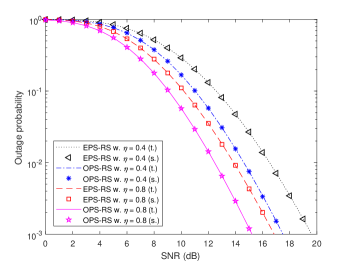
In Fig. 6, we show outage probability versus SNR of the EPS-RS and OPS-RS schemes for different energy conversion efficiencies of and . It is observed from Fig. 6 that given an energy conversion efficiency , the outage probabilities of EPS-RS and OPS-RS schemes decrease, as the SNR increases from dB to dB. Also, for both cases of and , the proposed OPS-RS scheme outperforms traditional EPS-RS method in terms of outage probability across the whole SNR region. Moreover, as the energy conversion efficiency increases from to , the outage performance of EPS-RS and OPS-RS improves accordingly.
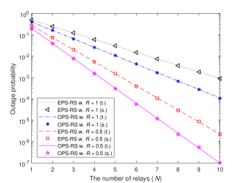
Fig. 7 depicts outage probability versus SNR of the EPS-RS and OPS-RS schemes for different number of EH relays of and , where both theoretical and simulated outage probabilities are given. It can be seen from Fig. 7 that for both the cases of and , the outage probabilities of EPS-RS and OPS-RS are reduced with an increasing SNR. Moreover, as the number of EH relays increases from to , the outage performance of both schemes improves significantly. One can also observe from Fig. 7 that given an SNR and the number of EH relays , the proposed OPS-RS scheme always outperforms traditional EPS-RS method in terms of the outage probability.
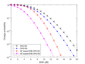
Fig. 8 shows outage probability versus the number of EH relays of the EPS-RS and OPS-RS schemes for different data rates of bit/s/Hz and bit/s/Hz. As seen from Fig. 8, for both cases of bit/s/Hz and bit/s/Hz, the outage probability of OPS-RS scheme is always better than that of traditional EPS-RS across the whole region of , and moreover, the performance advantage of proposed OPS-RS over EPS-RS becomes more significant with an increasing number of EH relays. Additionally, as the number of EH relays increases, outage probabilities of both EPS-RS and OPS-RS schemes are reduced substantially, implying significant benefits achieved by the joint power splitting and relay selection in terms of decreasing the outage probability, especially with an increasing number of EH relays.

In Fig. 9, we provide numerical outage probability comparisons among the EPS-RS and OPS-RS as well as the AF and DF based EHB-OPS-RS schemes. It is pointed out that the outage probability results of AF and DF based EHB-OPS-RS methods are obtained by using (58) and (75) with the aid of Monte-Carlo simulations. As shown in Fig. 9, the AF and DF based EHB-OPS-RS schemes outperform the EPS-RS and OPS-RS methods in terms of their outage probabilities. This is because that in the EPS-RS and OPS-RS schemes, the energies of the relays which have not been selected are just wasted without batteries equipped, which are, however, stored and used for subsequent information transmissions in the AF and DF based EHB-OPS-RS schemes, where the batteries are considered in the EH relays. Fig. 9 also shows that the outage probability of DF-based EHB-OPS-RS is much smaller than that of DF-based EHB-OPS-RS, implying the outage advantage of the DF protocol over AF strategy.
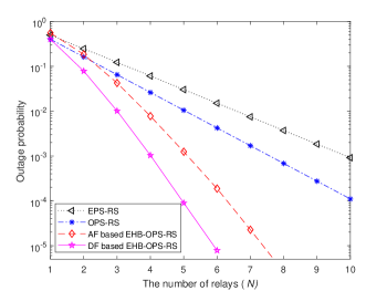
Fig. 10 depicts outage probability versus the number of EH relays () of the EPS-RS and OPS-RS as well as the AF and DF based EHB-OPS-RS schemes. As shown in Fig. 10, the outage probability performance of AF and DF based EHB-OPS-RS schemes are better than that of OPS-RS and EPS-RS methods, further demonstrating the benefit of exploiting the batteries in EH relays for reducing the outage probability of cooperative EH relay communications. One can also observe from Fig. 10 that the DF based EHB-OPS-RS substantially outperforms the AF based EHB-OPS-RS in terms of the outage probability. Moreover, the outage advantage of the DF based EHB-OPS-RS over the AF based EHB-OPS-RS becomes more significant, as the number of EH relays increases.
VII Conclusion
In this paper, we investigated the joint power splitting and relay selection for an energy-harvesting (EH) relay network consisting of a source, a destination, and multiple relays that are capable of harvesting energies from their received radio signals. We propose an optimal power splitting based relay selection (OPS-RS) framework, where a closed-form optimal PSR is obtained and an opportunistic relay selection strategy is presented. Also, the traditional equal power splitting based relay selection (EPS-RS) is considered for comparison purposes. We derived closed-form outage probability expressions for both OPS-RS and EPS-RS, based on which their diversity gains are characterized through an asymptotic outage analysis in the high signal-to-noise ratio region. The proposed OPS-RS framework was further extended to an energy-harvesting battery (EHB) enabled cooperative relay scenario, where an amplify-and-forward (AF) based EHB-OPS-RS and a decode-and-forward (DF) based EHB-OPS-RS schemes are proposed for AF and DF relay networks, respectively. Numerical results showed that the outage performance of proposed OPS-RS is better than the traditional EPS-RS, and moreover, the AF and DF based EHB-OPS-RS schemes both perform better than the OPS-RS and EPS-RS methods in terms of the outage probability. Additionally, as the number of EH relays increases, the outage probabilities of AF and DF based EHB-OPS-RS schemes both decrease, but an outage improvement of the DF based EHB-OPS-RS is much more significant than that of the AF based EHB-EPS-RS. In other words, the outage advantage of DF based EHB-OPS-RS over AF based EHB-OPS-RS becomes more substantial with an increasing number of EH relays.
Appendix A Proof of Proposition 1
Given an exponential random variable of with a mean of and denoting , we can obtain an expected value of as
| (A.1) |
where is known as the exponential integral function. Following (5.1.20) of [47], is bounded to
| (A.2) |
for . Noting and letting , we can easily obtain
| (A.3) |
and
| (A.4) |
and
| (A.5) |
Combining (A.2)-(A.5), we arrive at
| (A.6) |
Substituting (A.6) and into (A.1), we can obtain
| (A.7) |
from which one can readily have
| (A.8) |
which leads to
| (A.9) |
It can be seen from (A.9) that the expected value of , , converges to zero for .
Moreover, the expected value of can be obtained as
| (A.10) |
Substituting (A.3) and (A.6) into (10) yields
| (A.11) |
for . Substituting and into (A.11) and ignoring higher-order infinitesimals give
| (A.12) |
which leads to
| (A.13) |
Combining (A.9) and (A.13), the variance of can be obtained as
| (A.14) |
for .
As shown from (A.9) and (A.14), as the SNR goes to infinity, both the mean and variance of the random variable approach to zero. This means that the random variable approaches to zero for . Therefore, noting and considering , we can obtain
| (A.15) |
which completes the proof of Proposition 1.
References
- [1] Y. Zou, J. Zhu, and R. Zhang, “Exploiting network cooperation in green wireless communication,” IEEE Trans. Commun., vol. 61, no. 3, pp. 999-1010, Mar. 2013.
- [2] W. Sun and J. Liu, “2-to-M coordinated multipoint-based uplink transmission in ultra-dense cellular networks,” IEEE Trans. Wirel. Commun., vol. 17, no. 12, pp. 8342-8356, Dec. 2018.
- [3] G. Yang, Q. Zhang, and Y.-C. Liang, “Cooperative ambient backscatter communications for green Internet-of-Things,” IEEE Internet of Things Journal, vol. 5, no. 2, pp. 1116-1130, Apr. 2018.
- [4] G. Chen, J. Tang, and J. P. Coon , “Optimal routing for multihop social-based D2D communications in the Internet of Things,” IEEE Internet of Things Journal, vol. 5, no. 3, pp. 1880-1889, Jun. 2018.
- [5] L. Hu, H. Wen, B. Wu, et al., “Cooperative jamming for physical layer security enhancement in Internet of Things,” IEEE Internet of Things Journal, vol. 5, no. 1, pp. 219-228, Feb. 2018.
- [6] A. Nosratinia, T. E. Hunter and A. Hedayat, “Cooperative communication in wireless networks,” IEEE Commun. Mag., vol. 42, no. 10, pp. 74-80, Oct. 2004.
- [7] Y. Zou, Y.-D. Yao, and B. Zheng, “Cooperative relay techniques for cognitive radio systems: Spectrum sensing and secondary user transmissions,” IEEE Commun. Mag., vol. 50, no. 4, pp. 98-103, Apr. 2012.
- [8] Z. Bai, J. Jia, C.-X. Wang, and D. Yuan, “Performance analysis of SNR-based incremental hybrid decode-amplify-forward cooperative relaying protocol,” IEEE Trans. Commun., vol. 63, no. 6, pp. 2094-2106, Jun. 2015.
- [9] J. Yang, B. Champagne, Y. Zou, and L. Hanzo, “Centralized energy efficient multiuser multiantenna relaying in next-generation radio access networks,” IEEE Trans. Veh. Tech., vol. 66. no. 9, pp. 7913-7924, Sept. 2017.
- [10] U. Rashid, H. Tuan, H. Kha, and H. Nguyen, “Joint optimization of source precoding and relay beamforming in wireless MIMO relay networks,” IEEE Trans. Commun, vol. 62, no. 2, pp. 488-499, Feb. 2014.
- [11] H. Guo, Z. Yang, L. Zhang, J. Zhu, and Y. Zou, “Joint cooperative beamforming and jamming for physical-layer security of decode-and-forward relay networks,” IEEE Access, vol. 5, no. 1, pp. 19620-19630, Dec. 2017.
- [12] Y. Zou, Y.-D. Yao, and B. Zheng, “Opportunistic distributed space-time coding for decode-and-forward cooperation systems,” IEEE Trans. Signal Process., vol. 60, no. 4, pp. 1766-1781, Apr. 2012.
- [13] J. Laneman and G. Wornell, “Distributed space-time-coded protocols for exploiting cooperative diversity in wireless networks,” IEEE Trans. Inform. Theory, vol. 49, no. 10, pp. 2415-2425, Oct. 2003.
- [14] G. Scutari and S. Barbarossa, “Distributed space-time coding for regenerative relay networks,” IEEE Trans. Wirel. Commun., vol. 4, no. 5, pp. 2387-2399, Sept. 2005.
- [15] Y. Zou, J. Zhu, B. Zheng, and Y.-D. Yao, “An adaptive cooperation diversity scheme with best-relay selection in cognitive radio networks,” IEEE Trans. Signal Process., vol. 58, no. 10, pp. 5438-5445, Oct. 2010.
- [16] S. Ikki and M. H. Ahmed, “Performance analysis of adaptive decode-and-forward cooperative diversity networks with best-relay selection,” IEEE Trans. Commun., vol. 58, no. 1, pp. 68-72, Jan. 2010.
- [17] A. Bletsas, H. Shin, M. Z. Win, and A. Lippman, “A simple cooperative diversity method based on network path selection,” IEEE J. Select. Areas Commun., vol. 24, no. 3, pp. 659-672, Mar. 2006.
- [18] Y. Zhang, R. Yu, M. Nekovee, et al., “Cognitive machine-to-machine communications: Visions and potentials for the smart grid,” IEEE Network, vol. 26, no. 3, pp. 6-13, May 2012.
- [19] Y. Zhang, R. Yu, S. Xie, et al., “Home M2M networks: Architectures, standards, and QoS improvement,” IEEE Commun. Mag., vol. 49, no. 4, pp. 44-52, Apr. 2011.
- [20] W. Sun, J. Liu, and H. Zhang, “When smart wearables meet intelligent vehicles: Challenges and future directions,” IEEE Wirel. Commun. Mag., vol. 24, no. 3, pp. 58-65, Mar. 2017.
- [21] Z. Hou, H. Chen, Y. Li, and B. Vucetic, “Incentive mechanism design for wireless energy harvesting-based Internet of Things,” IEEE Internet of Things Journal, vol. 5, no. 4, pp. 2620-2632, Aug. 2018.
- [22] W. Sun and J. Liu, “Coordinated multipoint-based uplink transmission in Internet of Things powered by energy harvesting,” IEEE Internet of Things Journal, vol. 5, no. 4, pp. 2585-2595, Aug. 2018.
- [23] W. Sun, J. Liu, Y. Yue, et al., “Double auction-based resource allocation for mobile edge computing in industrial Internet of Things,” IEEE Trans. Ind. Inform., vol. 14, no. 10, pp. 4692-4701, Oct. 2018.
- [24] W. Sun, Y. Ge, and Z. Zhang, “An analysis framework for inter-user interference in IEEE 802.15.6 body sensor networks: A stochastic geometry approach,” IEEE Trans. Veh. Tech., vol. 65, no. 10, pp. 8567-8577, Oct. 2016.
- [25] B. Cao, Y. Li, L. Zhang, et al., “When Internet of Things meets blockchain: Challenges in distributed consensus,” IEEE Network, DOI: 10.1109/MNET.2019.1900002, Jul. 2019.
- [26] R. Zhang and C. K. Ho, “MIMO broadcasting for simultaneous wireless information and power transfer,” IEEE Trans. Wirel. Commun., vol. 12, no. 5, pp. 1989-2001, May 2013.
- [27] X. Zhou, R. Zhang and C. K. Ho, “Wireless information and power transfer: Architecture design and rate-energy tradeoff,” IEEE Trans. Commun., vol. 61, no. 11, pp. 4754-4767, Nov. 2013.
- [28] S. Wang, M. Xia, K. Huang, and Y. C. Wu, “Wirelessly powered two-way communication with nonlinear energy harvesting model: Rate regions under fixed and mobile relay,” IEEE Trans. Wirel. Commun., vol. 16, no. 12, pp. 8190-8204, Dec. 2017.
- [29] D. Mishra, S. De, and D. Krishnaswamy, “Dilemma at RF energy harvesting relay: Downlink energy relaying or uplink information transfer,” IEEE Trans. Wireless Commun., vol. 16, no.8, pp. 4939-4955, Aug. 2017.
- [30] T. Li, P. Fan and K. B. Letaief, “Outage probability of energy harvesting relay-aided cooperative networks over Rayleigh fading channel,” IEEE Trans. Veh. Tech., vol. 65, no. 2, pp. 972-978, Feb. 2016.
- [31] S. Xu, X. Qin and K. S. Kwak, “Energy harvesting based relay selection in cooperative wireless networks,” IEEE Veh. Tech. Conf., 2016, pp. 1-5.
- [32] N. Do, B. Vo, and A. Beongku, “Outage performance analysis of relay selection schemes in wireless energy harvesting cooperative networks over non-identical Rayleigh fading channels,” Sensors, vol. 16, no. 3, pp. 295, Feb. 2016.
- [33] D. Wang, R. Zhang, X. Cheng, and L. Yang, “Relay selection in power splitting based energy-harvesting half-duplex relay networks,” Proc. 2017 85th IEEE Veh. Tech. Conf., Sydney, Australia, Jun. 2017.
- [34] D. Wang, R. Zhang, X. Cheng, L. Yang, and C. Chen, “Relay selection in full-duplex energy-harvesting two-way relay networks,” IEEE Trans. Green Commun. Net., vol. 1, no. 2, pp. 182-191, Jun. 2017.
- [35] J. Men, J. Ge and C. Zhang, “A joint relay-and-antenna selection scheme in energy-harvesting MIMO relay networks,” IEEE Signal Process. Lett., vol. 23, no. 4, pp. 532-536, Apr. 2016.
- [36] X. Huang and N. Ansari, “Optimal cooperative power allocation for energy-harvesting-enabled relay networks,” IEEE Trans. Veh. Tech., vol. 65, no. 4, pp. 2424-2434, Apr. 2016.
- [37] Z. Ding, S. M. Perlaza, I. Esnaola and H. V. Poor, “Power allocation strategies in energy harvesting wireless cooperative networks,” IEEE Trans. Wirel. Commun., vol. 13, no. 2, pp. 846-860, Feb. 2014.
- [38] C. Huang, R. Zhang and S. Cui, “Optimal power allocation for outage probability minimization in fading channels with energy harvesting constraints,” IEEE Trans. Wirel. Commun., vol. 13, no. 2, pp. 1074-1087, Feb. 2014.
- [39] R. Yao, F. Xu, T. Mekkawy and J. Xu, “Optimised power allocation to maximise secure rate in energy harvesting relay network,” Electronics Letters, vol. 52, no. 22, pp. 1879-1881, Oct. 2016.
- [40] M. P. Deep, S. Jain, and P. Ubaidulla, “Relay selection and resource allocation for energy harvesting cooperative networks,” Proc. 2017 85th IEEE Veh. Tech. Conf., Sydney, Australia, Jun. 2017.
- [41] A. Alsharoa, H. Ghazzai, A. E. Kamal and A. Kadri, “Optimization of a power splitting protocol for two-way multiple energy harvesting relay system,” IEEE Trans. Green Commun. Net., vol. 1, no. 4, pp. 444-457, Dec. 2017.
- [42] E. Boshkovska, D. W. K. Ng, N. Zlatanov, and R. Schober, “Practical nonlinear energy harvesting model and resource allocation for SWIPT systems,” IEEE Commun. Lett., vol. 19, no. 12, pp. 2082-2085, Dec. 2015.
- [43] Y. Dong, M. J. Hossain and J. Cheng, “Performance of wireless powered amplify and forward relaying over Nakagami-m fading channels with nonlinear energy harvester,” IEEE Commun. Lett., vol. 20, no. 4, pp. 672-675, Apr. 2016.
- [44] I. Gradshteyn and I. Ryzhik, Tables of Integrals, Series, and Products (7th Edition), New York: Academic Press, 2007.
- [45] L. Zheng and D. Tse, “Diversity and multiplexing: A fundamental tradeoff in multiple antenna channels,” IEEE Trans. Inf. Theory, vol. 49, no. 5, pp. 1073-1096, May 2003.
- [46] Y. Zou, Y.-D. Yao, and B. Zheng, “Diversity-multiplexing tradeoff in selective cooperation for cognitive radio,” IEEE Trans. Commun., vol. 60, no. 9, pp. 2467-2481, Sept. 2012.
- [47] M. Abramowitz and I. Stegun, Handbook of Mathematical Functions, New York: Dover, 1964.
![[Uncaptioned image]](/html/1901.03301/assets/x11.png) |
Yulong Zou (SM’13) is a Full Professor and Doctoral Supervisor at the Nanjing University of Posts and Telecommunications (NUPT), Nanjing, China. He received the B.Eng. degree in information engineering from NUPT, Nanjing, China, in July 2006, the first Ph.D. degree in electrical engineering from the Stevens Institute of Technology, New Jersey, USA, in May 2012, and the second Ph.D. degree in signal and information processing from NUPT, Nanjing, China, in July 2012. Dr. Zou was awarded the 9th IEEE Communications Society Asia-Pacific Best Young Researcher in 2014. He has served as an editor for the IEEE Communications Surveys & Tutorials, IEEE Communications Letters, EURASIP Journal on Advances in Signal Processing, IET Communications, and China Communications. In addition, he has acted as TPC members for various IEEE sponsored conferences, e.g., IEEE ICC/GLOBECOM/WCNC/VTC/ICCC, etc. |
![[Uncaptioned image]](/html/1901.03301/assets/x12.png) |
Jia Zhu is a Full Professor at the Nanjing University of Posts and Telecommunications (NUPT), Nanjing, China. She received the B.Eng. degree in Computer Science and Technology from the Hohai University, Nanjing, China, in July 2005, and the Ph.D. degree in Signal and Information Processing from the Nanjing University of Posts and Telecommunications, Nanjing, China, in April 2010. From June 2010 to June 2012, she was a Postdoctoral Research Fellow at the Stevens Institute of Technology, New Jersey, the United States. Her general research interests include the cognitive radio, physical-layer security, and communications theory. |
![[Uncaptioned image]](/html/1901.03301/assets/x13.png) |
Xiao Jiang received the M. Eng degree in signal and information processing from the Nanjing University of Posts and Telecommunications (NUPT), Nanjing, China, in April 2019. His research interests include energy harvesting, physical-layer security, and cooperative communications. |