Characterizing nonlocal dispersion compensation in deployed telecommunications fiber
Abstract
Propagation of broadband photon pairs over deployed telecommunication fibers is used to achieve nonlocal dispersion compensation without the deliberate introduction of negative dispersion. This is made possible by exploiting time-energy entanglement and the positive and negative dispersive properties of the fiber. We demonstrate preservation of photon timing correlations after transmission over two multi-segment spans of deployed fiber and up to of laboratory-based fiber.
Correlated photon pairs created via spontaneous parametric downconversion (SPDC) are a core component in entanglement based quantum key distribution (QKD) Jennewein et al. (2000); Ribordy et al. (2001); Poppe et al. (2004); Ursin et al. (2007); Hübel et al. (2007); Marcikic, Lamas-Linares, and Kurtsiefer (2006); Honjo et al. (2008); Peloso et al. (2009); Inagaki et al. (2013); Yin et al. (2017), and may also be used as a resource for clock synchronization Valencia, Scarcelli, and Shih (2004); Ho, Lamas-Linares, and Kurtsiefer (2009). Photon pairs produced by this mechanism are created within a short time window (typically O’Donnell (2011)), and so share a high degree of temporal correlation. As the SPDC process is inherently broadband, fiber chromatic dispersion can obscure these timing correlations. For this reason, photon pair sources are often filtered spectrally prior to use in optical fiber systems, reducing the throughput of the entire system Fasel et al. (2004); Wengerowsky et al. (2018).
Management and engineering of dispersion are routine tasks in fiber optic communications Keiser (2003); Ainslie and Day (1986). In 1992, Franson Franson (1992) showed that photon pairs entangled in the time-energy basis could experience nonlocal compensation of chromatic dispersion, provided the photons propagate through media with opposite dispersion coefficients. This is a direct consequence of quantum correlations, and therefore impossible to replicate with classical light – a concept later expanded by Wasak et al. Wasak et al. (2010), who proposed the preservation of tight timing correlations in the presence of dispersive transmission as an entanglement witness.
This effect has been observed in the visible or near-infrared spectral range by using dispersive elements such as prisms, gratings and specialized fibers Steinberg, Kwiat, and Chiao (1992); O’Donnell (2011); Baek, Cho, and Kim (2011); Maclean, Donohue, and Resch (2018). However, both negative and positive dispersion regions are available in single-mode optical fibers Cohen and Lin (1977). Most deployed telecommunication fiber exhibits this behaviour around the zero dispersion wavelength close to the “O-band” Ainslie and Day (1986), with the location of this region specified by International Telecommunications Union standards (ITU-T G.652 G65 (2016)).
Nonlocal dispersion compensation using the properties of a single optical fiber was first observed in measurements of fiber dispersion using SPDC photons Brendel, Zbinden, and Gisin (1998) and was applied to QKD field tests Tittel et al. (1998) and entanglement distribution Tittel et al. (1999). These experiments utilized a tunable source of SPDC photons to generate wavelengths that would experience dispersion compensation in two continuous spans of deployed telecommunications fiber with lengths up to . These early experiments illustrate the potential for nonlocal dispersion compensation to increase the signal-to-noise ratio of a quantum channel.
In this paper, we show that photon pairs broadly degenerate at the approximate location of the zero dispersion wavelength can exhibit nonlocal dispersion compensation in standard, multi-segment telecommunication fiber. This scheme does not require specialized dispersive elements, measurement of the precise fiber characteristics or tuning of the emission spectrum.
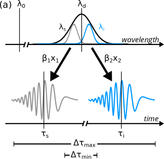
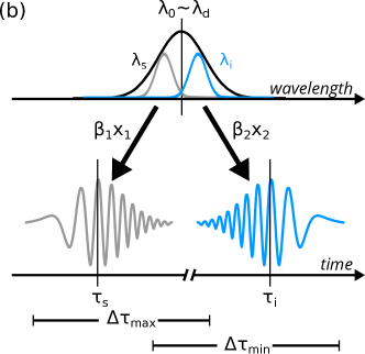
Nonlocal dispersion compensation can be understood by considering the energy anticorrelation of an entangled photon pair and dispersion on the individual photon wavepackets. In the presence of dispersion, “fast” components of a photon are correlated with the “slow” components of its sister photon. For positive dispersion, higher energy (shorter wavelength) components of a light pulse travel faster, while lower energy components lag behind Saleh, Teich, and Saleh (1991). This leads to a “chirp”. The minimum and maximum delay ( and ) between the detection of the photons determine the spread in observed timing correlations (Figure 1a). For opposite dispersion coefficients (Figure 1b) the chirp imparted on one of the photons is reversed, and the resulting fast-fast/slow-slow correlations minimize the spread in propagation times.
The width of the timing distribution is related to the sum of the dispersion along the two paths ( and for photons 1 and 2, respectively) Franson (1992),
| (1) |
where is the coherence time of the photons, and , are the propagation distances. If the dispersion coefficients and have opposite sign, dispersion can be at least partially compensated. For the compensation is perfect Franson (1992).
Figure 2 shows a schematic of the experimental setup. A photon pair source is connected to two remote nodes by optical fiber. At the nodes, arrival times of single photons are recorded with respect to a local clock. Due to the timing correlation of the photon pairs, detection times and at node A and B are correlated. As photon pairs are created at random time intervals, their detection results in a random set of arrival times at each node. These are processed into sets of delays ( and ) such that
| (2) |

with their cross correlation c()
| (3) |
This cross correlation will exhibit a peak at a delay corresponding to the relative time of flight of the single photons. The identification of this peak allows the pairing of corresponding detection events Marcikic, Lamas-Linares, and Kurtsiefer (2006). In several entanglement-based quantum key distribution systems Marcikic, Lamas-Linares, and Kurtsiefer (2006); Ursin et al. (2007), the presence of significant propagation losses along with a degree of background noise makes minimizing the width of this peak an important consideration Diamanti et al. (2016).
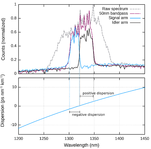
Our photon pair source is based on Type-0 SPDC in a periodically poled crystal of potassium titanyl phosphate (PPKTP, Raicol) pumped by a grating stabilized laser diode at (Ondax). The resulting photon pairs are degenerate at , close to the zero dispersion wavelength in the most common single-mode telecommunications fibers G65 (2016), with emission sufficiently broad to span a region on either side of this wavelength (see Figure 3). Signal and idler photons are efficiently separated using a wavelength division demultiplexer, and routed to either a deployed fiber link or a bank of lab-based fibers. After propagation and dispersion, we detect the photons using commercially available InGaAs avalanche photodiodes (APDs) operated in Geiger mode and record arrival times using timestamping modules.
There is an intrinsic uncertainty in the delay between the detection of a photon and the emission of a macroscopic electrical signal. For avalanche photodiodes, this jitter is usually of the order of hundreds of picoseconds Lunghi et al. (2012); Stipcevic, Wang, and Ursin (2013), while for superconducting nanowire sensors it can be as little as tens of picoseconds Natarajan, Tanner, and Hadfield (2012). This uncertainty, along with the resolution of timestamping electronics provides a lower bound to the width of correlation . The InGaAs APDs used in our work exhibit a jitter of and .
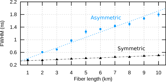
To probe the interaction of photon pairs with the dispersive properties of optical fiber, we transmit photons through several lengths of fiber from , cut from the same piece in order to maintain similar zero dispersion wavelengths. Figure 4 shows the width of for the assymetric case of one photon detected directly while the other is first dispersed by an optical fiber. An approximately linear relationship is observed between propagation distance and correlation width, with gradient . We also investigate the symmetric case where both photons are transmitted over the same fiber, before being separated and detected. In the symmetric case, dispersion is reduced to . This reduction is in agreement with Equation 1, consistent with . While perfect compensation could be achieved by tailoring the degenerate wavelength to of the specific fiber, this is impractical in deployed networks comprising fibers with different .
We carry out the symmetric measurement for longer fibers, with correlation signals shown in Figure 5. These fibers are comprised of several segments connected in series, with the longest () made up of three segments (10, 20, ). We no longer observe the linear increase of dispersion with fiber length (Figure 4). However, tight timing correlations are preserved (). We attribute small differences in the degree of dispersion compensation to variation in the exact position of the zero dispersion wavelength, which by specification may lie in a relatively wide range of SMF (2005).
It is interesting to note that the degree of compensation seen in the series of shorter fibers is lower than for any of the longer spools. For example the observed FWHM after of symmetric propagation is , compared with (Figure 5). This observation suggests that significant compensation is possible without tuning of the source.
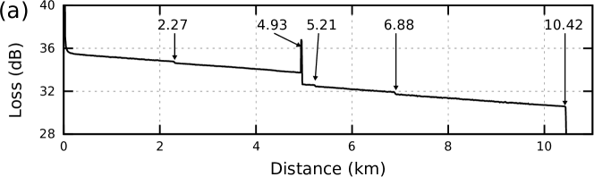
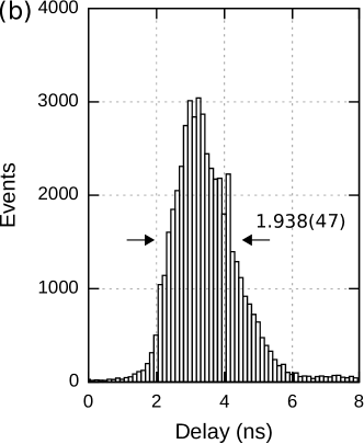
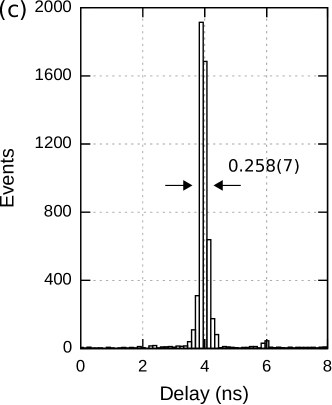
To test this mechanism in an operationally useful context we transmit photons through two separate spans of deployed telecommunication fiber. An optical time domain reflectometer (OTDR) measurement for one fiber is shown in Figure 6a, revealing at least five segments. From our previous observations we do not expect these segments to exhibit identical zero dispersion wavelengths. Measured histograms for one photon transmitted and one detected locally and for both photons transmitted are shown in Figure 6b and 6c. With only one photon transmitted, chromatic dispersion results in a coincidence distribution with a FWHM of . When both photons are transmitted over separate fibers, we observe a distribution with FWHM .

Laboratory and field test measurements unambiguously demonstrate that photon pairs with appropriately engineered spectral properties can experience self-compensation of dispersion in conventional telecommunication fiber networks. This is despite the presence of a range of zero dispersion wavelengths and accomplished without the requirement of source tuning. This capability paves the way for the use of broad spectrum entangled light sources for quantum key distribution and other forms of quantum communication. The use of the intrinsic anomalous dispersion available in standard telecommunications fiber can minimize or even remove the need for specialized dispersion-compensating apparatus. The trade-off of operating in the O-band (where attenuation losses are higher than in the more commonly used C-band) will be acceptable for many use cases, particularly for metropolitan areas with substantial existing fiber infrastructure.
Funding
This research is supported by the National Research Foundation, Prime Minister’s Office, Singapore under its Corporate Laboratory@University Scheme, National University of Singapore, and Singapore Telecommunications Ltd.
Acknowledgements
The authors thank Amelia Tan Peiyu and the Singtel fiber team for facilitating our deployed fiber tests.
References
- Jennewein et al. (2000) T. Jennewein, C. Simon, G. Weihs, H. Weinfurter, and A. Zeilinger, Physical Review Letters 84, 4729 (2000), arXiv:9912117 [quant-ph] .
- Ribordy et al. (2001) G. Ribordy, J. Brendel, J. D. Gautier, N. Gisin, and H. Zbinden, Physical Review A - Atomic, Molecular, and Optical Physics 63, 012309 (2001), arXiv:0008039v2 [arXiv:quant-ph] .
- Poppe et al. (2004) A. Poppe, A. Fedrizzi, T. Loruenser, O. Maurhardt, R. Ursin, H. R. Boehm, M. Peev, M. Suda, C. Kurtsiefer, H. Weinfurter, T. Jennewein, and A. Zeilinger, Quantum Optics 12, 5 (2004), arXiv:0404115 [quant-ph] .
- Ursin et al. (2007) R. Ursin, F. Tiefenbacher, T. Schmitt-Manderbach, H. Weier, T. Scheidl, M. Lindenthal, B. Blauensteiner, T. Jennewein, J. Perdigues, P. Trojek, B. Ömer, M. Fürst, M. Meyenburg, J. Rarity, Z. Sodnik, C. Barbieri, H. Weinfurter, and a. Zeilinger, Nature Physics 3, 481 (2007), arXiv:arXiv:1203.0980 .
- Hübel et al. (2007) H. Hübel, M. R. Vanner, T. Lederer, B. Blauensteiner, T. Lorünser, A. Poppe, and A. Zeilinger, Optics Express 15, 7853 (2007), arXiv:0801.3620 .
- Marcikic, Lamas-Linares, and Kurtsiefer (2006) I. Marcikic, A. Lamas-Linares, and C. Kurtsiefer, Applied Physics Letters 89, 2004 (2006), arXiv:0606072 [quant-ph] .
- Honjo et al. (2008) T. Honjo, S. W. Nam, H. Takesue, Q. Zhang, H. Kamada, Y. Nishida, O. Tadanaga, M. Asobe, B. Baek, R. Hadfield, S. Miki, M. Fujiwara, M. Sasaki, Z. Wang, K. Inoue, and Y. Yamamoto, Optics Express 16, 19118 (2008).
- Peloso et al. (2009) M. P. Peloso, I. Gerhardt, C. Ho, A. Lamas-Linares, and C. Kurtsiefer, New Journal of Physics 11 (2009), 10.1088/1367-2630/11/4/045007, arXiv:0812.1880 .
- Inagaki et al. (2013) T. Inagaki, N. Matsuda, O. Tadanaga, M. Asobe, and H. Takesue, Optics Express 21, 23241 (2013), arXiv:1310.5473 .
- Yin et al. (2017) J. Yin, Y. Cao, Y.-h. Li, J.-g. Ren, S.-k. Liao, L. Zhang, W.-q. Cai, W.-y. Liu, B. Li, H. Dai, M. Li, Y.-m. Huang, L. Deng, L. Li, Q. Zhang, N.-l. Liu, Y.-a. Chen, C.-y. Lu, R. Shu, C.-z. Peng, J.-y. Wang, and J.-w. Pan, Physical Review Letters 200501, 1 (2017).
- Valencia, Scarcelli, and Shih (2004) A. Valencia, G. Scarcelli, and Y. Shih, Applied Physics Letters 85, 2655 (2004), arXiv:0407204 [quant-ph] .
- Ho, Lamas-Linares, and Kurtsiefer (2009) C. Ho, A. Lamas-Linares, and C. Kurtsiefer, New Journal of Physics 11, 1 (2009), arXiv:0901.3203 .
- O’Donnell (2011) K. A. O’Donnell, Physical Review Letters 106, 1 (2011), arXiv:1103.0532 .
- Fasel et al. (2004) S. Fasel, N. Gisin, G. Ribordy, and H. Zbinden, European Physical Journal D 30, 143 (2004), arXiv:0403144v1 [arXiv:quant-ph] .
- Wengerowsky et al. (2018) S. Wengerowsky, S. K. Joshi, F. Steinlechner, J. R. Zichi, S. Dobrovolskiy, R. van der Molen, J. W. Los, V. Zwiller, M. A. Versteegh, A. Mura, et al., arXiv preprint arXiv:1803.00583 (2018).
- Keiser (2003) G. Keiser, “Optical fiber communications,” in Wiley Encyclopedia of Telecommunications (Wiley Encyclopedia of Telecommunications, 2003) https://onlinelibrary.wiley.com/doi/pdf/10.1002/0471219282.eot158 .
- Ainslie and Day (1986) B. J. Ainslie and C. R. Day, Journal of Lightwave Technology LT-4 (1986).
- Franson (1992) J. D. Franson, Physical Review A 45, 3126 (1992).
- Wasak et al. (2010) T. Wasak, P. Szańkowski, W. Wasilewski, and K. Banaszek, Physical Review A - Atomic, Molecular, and Optical Physics 82 (2010), 10.1103/PhysRevA.82.052120, arXiv:1006.5854 .
- Steinberg, Kwiat, and Chiao (1992) A. M. Steinberg, P. G. Kwiat, and R. Y. Chiao, Physical Review Letters 68, 2421 (1992), arXiv:0000135489 .
- Baek, Cho, and Kim (2011) S. Y. Baek, Y. W. Cho, and Y. H. Kim, 2011 IEEE Photonics Society Summer Topical Meeting Series 17, 35 (2011), arXiv:0811.2035 .
- Maclean, Donohue, and Resch (2018) J. P. W. Maclean, J. M. Donohue, and K. J. Resch, Physical Review Letters 120, 53601 (2018), arXiv:1710.11541 .
- Cohen and Lin (1977) L. G. Cohen and C. Lin, Applied Optics 16, 2 (1977).
- G65 (2016) Characteristics of a single-mode optical fibre and cable, International Telecommunications Union, Geneva, CH (2016), iTU-T G.652 Version 9.0.
- Brendel, Zbinden, and Gisin (1998) J. Brendel, H. Zbinden, and N. Gisin, Optics Communications 151, 35 (1998).
- Tittel et al. (1998) W. Tittel, J. Brendel, H. Zbinden, and N. Gisin, Phys. Rev. Lett. 2, 69 (1998).
- Tittel et al. (1999) W. Tittel, J. Brendel, N. Gisin, and H. Zbinden, Physical Review A - Atomic, Molecular, and Optical Physics 59, 4150 (1999), arXiv:9809025 [quant-ph] .
- Saleh, Teich, and Saleh (1991) B. E. Saleh, M. C. Teich, and B. E. Saleh, Fundamentals of photonics, Vol. 22 (Wiley New York, 1991).
- Diamanti et al. (2016) E. Diamanti, H.-k. Lo, B. Qi, and Z. Yuan, npj Quantum Information 16025 (2016), 10.1038/npjqi.2016.25, arXiv:1606.05853 .
- Lunghi et al. (2012) T. Lunghi, C. Barreiro, O. Guinnard, R. Houlmann, X. Jiang, M. a. Itzler, and H. Zbinden, Journal of Modern Optics 59, 1 (2012), arXiv:arXiv:1204.4594v1 .
- Stipcevic, Wang, and Ursin (2013) M. Stipcevic, D. Wang, and R. Ursin, Journal of Lightwave Technology 31, 3591 (2013).
- Natarajan, Tanner, and Hadfield (2012) C. M. Natarajan, M. G. Tanner, and R. H. Hadfield, Superconductor Science and Technology 25, 063001 (2012).
- SMF (2005) Corning ® SMF-28e ® Optical Fiber Produt Information, Corning Inc. (2005).