Swansea University
Swansea, Wales
SA1 8EN
j.h.stovold@swansea.ac.uk
Trainable Associative Memory Neural Networks in a Quantum-Dot Cellular Automata
Abstract
Quantum-dot cellular automata (QCAs) offer a diffusive computing paradigm with picosecond transmission speed, making them an ideal candidate for moving diffusive computing to real-world applications. By implementing a trainable associative memory neural network into this substrate, we demonstrate that high-speed, high-density associative memory is feasible through QCAs. The presented design occupies per neuron, which translates to circa , or of memory storage, offering a real possibility for large-scale associative memory circuits. Results are presented from simulation, demonstrating correct working behaviour of the associative memory in single neurons, two-neuron and four-neuron arrays.
1 Introduction
Quantum-dot cellular automata (QCAs) are a transistor-less computing paradigm that uses a bistable arrangement of electrons within quantum dots to represent binary values [6, 15]. The QCA paradigm [33] offers a route towards real-world application for computational constructs that have been developed in naturally diffusive systems, such as reaction–diffusion chemistry [26, 28, 27, 1], slime mould [24], and billiard ball computing [4].
This paper presents a QCA-based associative memory neural network, in the form of a correlation matrix memory (CMM). A CMM is a weightless neural network that associates stimulus–response pairs [10]. CMMs have been successfully applied to a wide range of problems, including address matching for the UK Post Office [17], matching patterns in chemical structures [34], and image processing [2].
QCA-based neural networks, such as those presented in this paper, have the potential for high-speed pattern matching on a scale that exceeds that of the human brain by multiple orders of magnitude. The human brain has a neuronal density of approx. [12], whereas the proposed neural network occupies approx. per neuron, giving a potential neuronal density of approx. .
This paper is structured as follows: the preliminary background of QCAs and CMMs are presented in section 2; section 3 presents the implementation of CMMs in QCA, starting with a single neuron, moving up to arrays of 2 and 4 neurons; finally, section 4 concludes the paper. Due to space constraints the simulation results for four-neuron arrays and horizontal two-neuron arrays are provided in the appendix.
2 Preliminaries
2.1 Quantum-Dot Cellular Automata
Quantum-dot cellular automata (QCAs) are a transistor-less computing paradigm [15]. A QCA consists of a regular array of ‘QCA cells’, each consisting of four quantum dots and two electrons (see fig. 1(a)). The cell is arranged such that the electrons are free to tunnel between quantum dots within an individual cell, but not to neighbouring cells. An electron moves based on the Coulomb repulsion forces of the other electron in the cell and of those in neighbouring cells. As such, the cell has two stable states with and polarisation. By treating these stable polarisation states as logical 0 and 1 respectively, logical circuits can be constructed [32].

QCA circuits can be clocked by varying the tunneling potential between each quantum dot [13]. The tunneling potential determines whether the electron can tunnel from one dot to another. As depicted in fig. 1(c) and (d), by varying this potential over time, the electron can be held in place or be allowed to switch freely. This provides a mechanism through which directional propagation of state can be achieved. Fig. 1(b) shows how this varying clock signal is depicted in this paper. In QCADesigner [38]—the simulator used in section 3—these are represented by the colours green, pink, blue, and white.
The basic building blocks of logical circuits were constructed by Tougaw and Lent [32], who demonstrated that signals can propagate along a ‘wire’ of QCA cells [14] (see fig. 2(a)) and that logical devices can be constructed, including logical inverters (b) and a majority gate (c). The three-input majority gate can be used to implement a two-input AND or OR gate, depending on the value of the third input (logical 0 for AND, 1 for OR).

2.2 Correlation Matrix Memories
Associative memory is a form of memory that associates stimulus–response pairs. In biological systems, the memory results from temporal associations that emerge between two sets of interacting neurons [20, 21, 40]. As the stimulus is presented to the first set of neurons, the response of those neurons is sent to the second set of neurons, which subsequently respond. As this second response is similar each time, the network of neurons can be said to have learnt the association between the two signals.
The CMM (Correlation Matrix Memory) is a matrix-based representation of this process [10]. The two sets of interacting neurons can be represented as a fully-connected, two-layer artificial neural network (one input layer, one output layer; see fig. 3b). Associative memory can be formed by presenting stimulus–response pairs of binary vectors, training the connections between the two layers. The CMM is the binary weight matrix that connects these two layers.
For example, the network in fig. 3b would be represented by the CMM, , with input–output pairs and in fig. 3a.
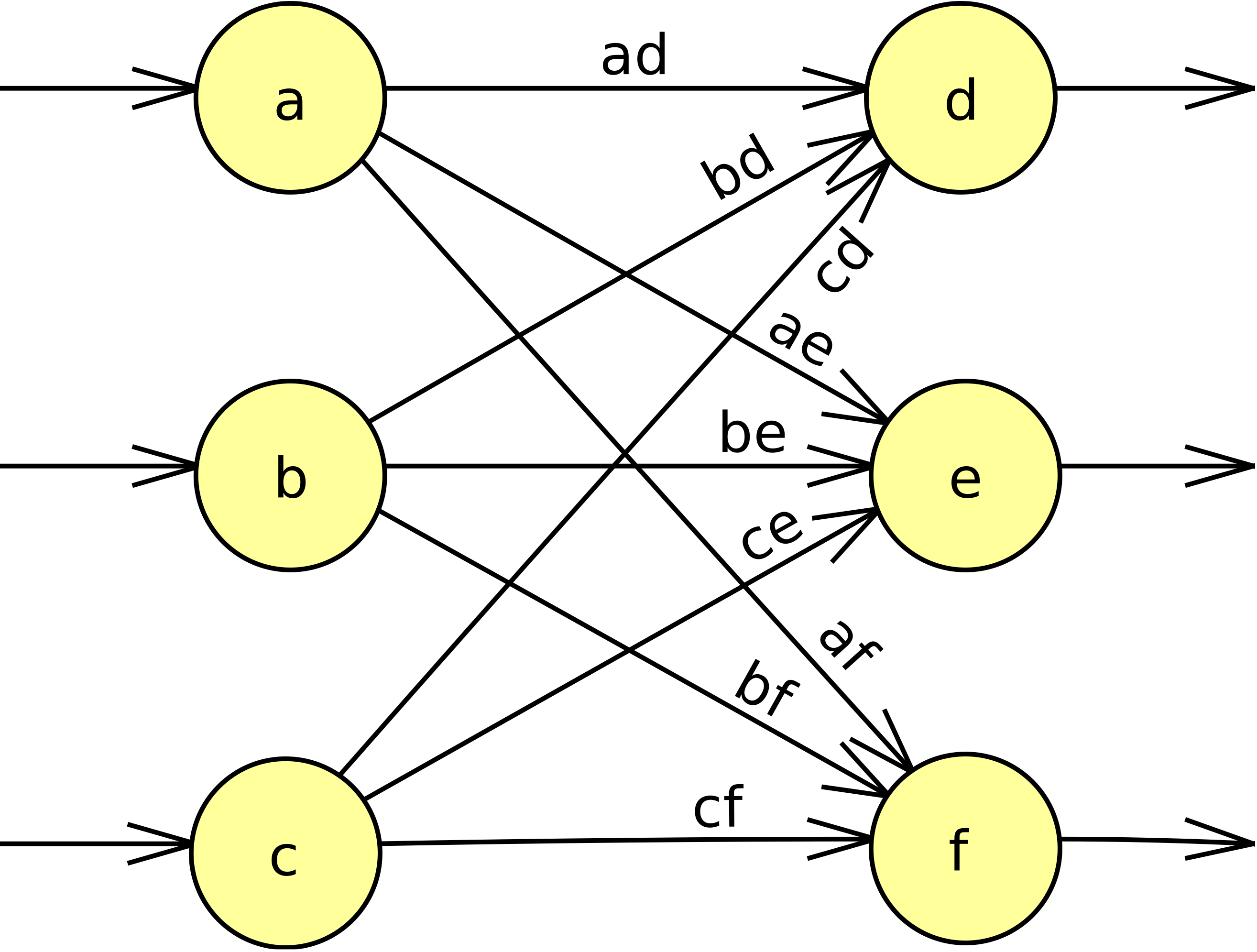
Before training, the initial matrix is filled with zeros (as there are no associations stored in the network). As the binary-valued input–output pairs are presented to the network, associations are built up in the matrix . These associations are stored as 1s in the matrix, corresponding to coincident 1s in both input and output vectors. For example, in fig. 3a, if and were both 1 then would be set to 1 after training.
To recall, an input pattern is presented to the network: [9]
where is the input pattern, and is the output from the network trained with associations stored in . The desired output pattern, is currently combined with noise from the other patterns stored in the network, , hence:
Thresholding the output vector leaves the desired output vector . Different thresholding strategies offer different advantages in terms of the ability of the network to generalise from noisy or incomplete patterns to a correct output [2].
The ability of the network to generalise noisy inputs suggests a range of applications in real-world environments, where a noisy signal is far more common than a clean signal. Example applications areas include stock market prediction [11], fault detection [16], address matching [17], associating signals in robots [25, 29] and image processing [2].
3 Implementation
This section presents the QCA-based implementation of CMMs. Throughout this section, the correct behaviour of the designs has been demonstrated through a simulator called QCADesigner [38].
3.1 Individual Neurons
The essence of the CMM neuron is to detect and store coincident input bits between binary arrays (see section 2.2). Coincidence detection is achievable using a logical AND gate, which is achievable using a majority gate with one of the inputs fixed to logical 0 ( polarisation) [32]. Combining this AND gate with a memory cell is enough to detect and store the coincidence of logical 1 inputs.
Fig. 4 shows the logical design and implementation for a single CMM neuron in QCADesigner. Two single-bit inputs (x_in and y_in) represent single bits in the two binary vectors presented to the CMM during the training phase of the network. Note that the x_in and y_in wires are on different levels to the main neuron, to prevent interference between input signals, although this is not required it makes simulating the design simpler [7]. To recall the value from the neuron, the x_in input is set to 1, which allows the AND gate below the memory cell to pass the value of the memory cell to z_out.

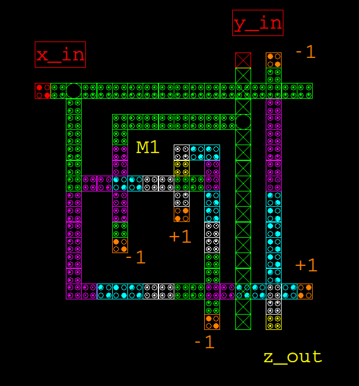
Fig. 5 shows the signal traces from simulating the neuron depicted in fig. 4. The memory cell within the CMM neuron (M1) is only set to 1 when both inputs are 1, and the output from the neuron (z_out) is set to 1 when the memory cell is set and x_in is set to 1, demonstrating that the stored value can be recalled.

3.2 2-neuron array
The logical next step in developing a usable QCA-based CMM is to connect multiple neurons together. Connecting multiple neurons in a vertical and horizontal arrangement is not necessarily trivial: Coloumb interference between neurons, crossing lines of cells, and long chains of cells in a wire can all introduce unexpected effects.
Fig. 6 shows the selected approach to connecting multiple neurons together, in horizontal and vertical form. In this case, the problem of dealing with crossing lines of quantum-dot cells has been the focus, as the other problems only tend to appear in larger circuits. By keeping x_in and y_in on different layers to the main neuronal circuit, the design prevents these signals from interfering with the learning behaviour, and allows the same signal to be passed to both neurons within the same clock cycle.
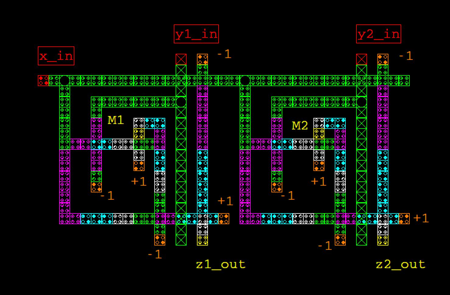
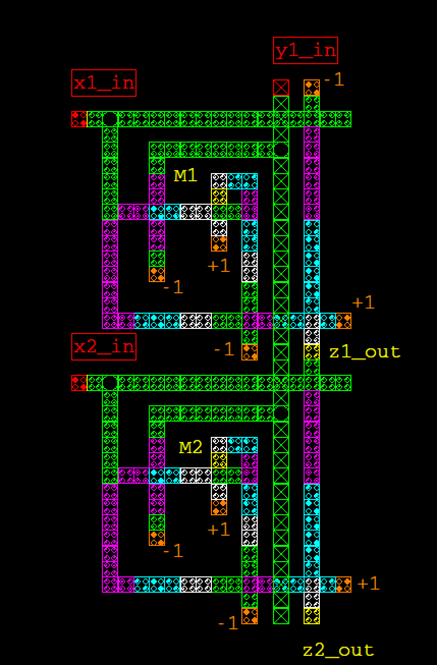
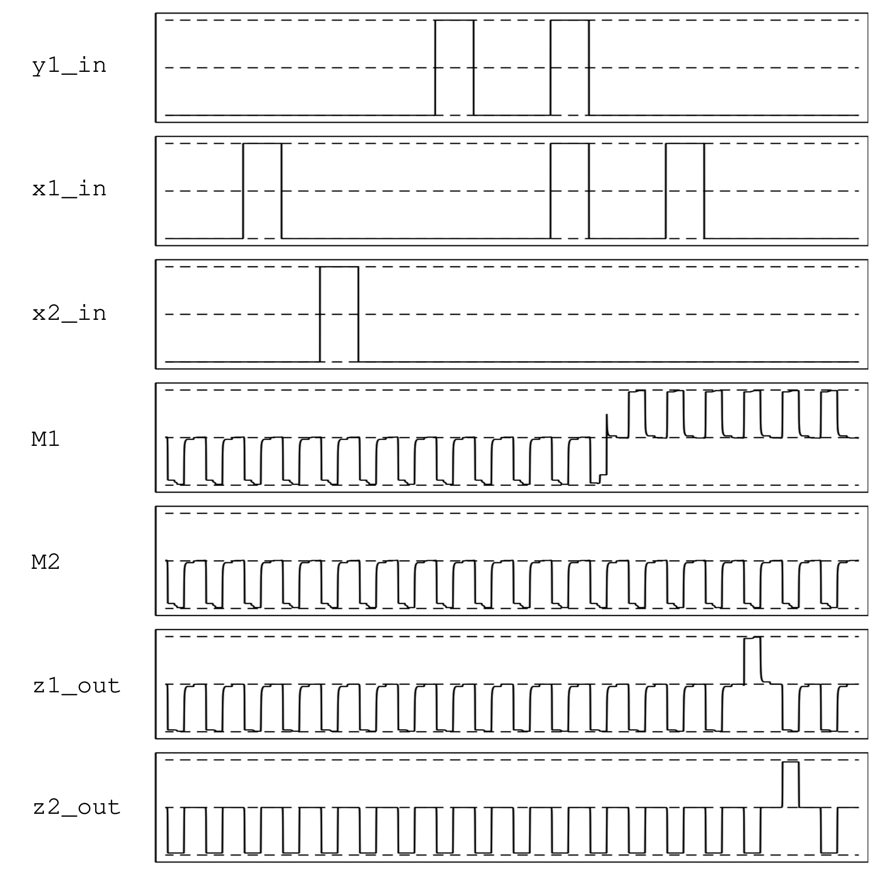
As with the single neuron testing phase, the behaviour of the neurons are tested using simulation to demonstrate that both horizontal and vertical arrangements of neurons train and recall as expected. Fig. 7 shows the results of the simulations, where the vertical CMM array is trained based on the input bit vectors, and the information subsequently recalled from the network. Due to space constraints, the simulation results for the horizontal arrangement is provided in the appendix.
The z2_out signal in fig. 7 shows a logical 1 output immediately after z1_out shows a logical 1 output as the signal is passed down through the same line of QCA cells. This does not signify that z2_out is outputting a value, merely that the vertical combination of neurons is effectively using the QCA wire as intended.
3.3 4-neuron array
Unlike with the two-neuron case presented in section 3.2, problems were encountered when scaling to four neurons. The main issue was with the long lines of cells that act as wires in the QCA. Once they exceeded a certain length, they would not consistently communicate the signal from one end to the other.
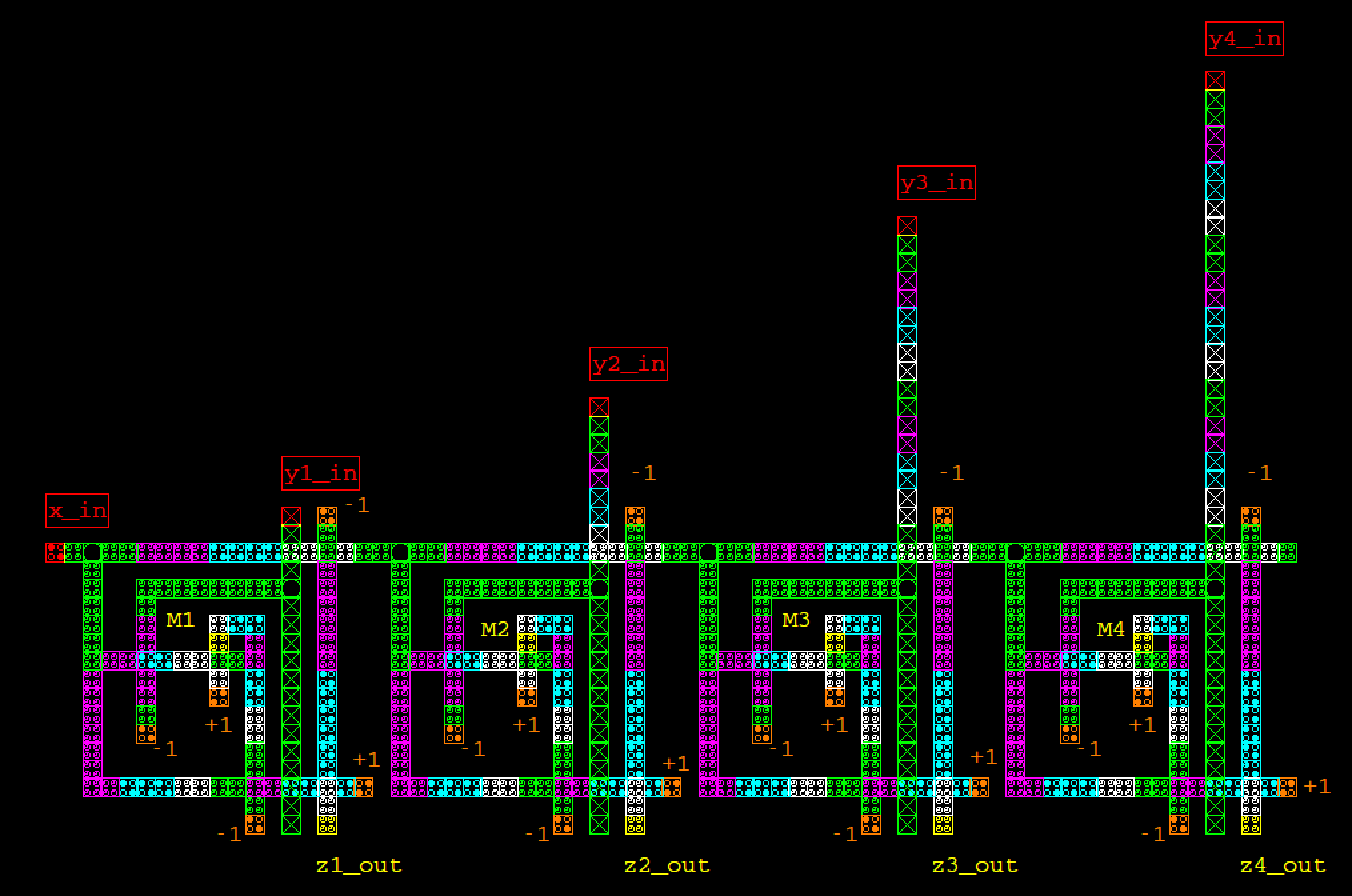
This is likely a result of the clock speed being too high. As the propagation of state across the QCA cells takes time (around 2ps/cell [33]), the clock signal may change before the signal has reached the end of the QCA wire.111It is possible this is an artefact of the simulation, rather than a real-world problem, as it is expected that the clock signal will also experience propagation delay To alleviate this problem, a clock cycle was introduced between each neuron on the x_in wire that meant the signal was only required to transmit over a smaller distance within each clock cycle. In order to make sure the signals reach the neurons on the same clock cycles, a delay was also introduced on the y_in inputs.
Once the clocking mechanism was introduced into the CMM, four-neuron arrays were successfully implemented (see fig. 8). One of the negative side-effects of using this clocking method is that some of the parallelism that is so attractive for this substrate is lost—by using clocking, large arrays of neurons will take longer to train, changing from O(1) to O(n), where n is the number of clock cycles. If this problem is solved, this would prove to be an efficient method for training associative memory neural networks in QCAs. Due to space constraints, the simulation results for the four-neuron case are available in appendix 0.A.
4 Discussion
This is the first implementation of associative memory in quantum-dot cellular automata. Given the pattern-matching abilities of CMMs, and the ability to generalise from noisy inputs, this design could place CMMs at the forefront of QCA applications, once the fabrication of QCAs becomes efficient. The presented design has the potential to store circa ( per bit), or , multiple orders of magnitude higher than the density of neurons in the human brain [12].
The main limitation with the current proposed design is the need to introduce a clock delay on larger neuron arrays (see section 3.3). This drastically reduces the speed with which the CMM can be trained (from O(1) to O(n)). Removing this extra clock delay is currently the subject of further study.
Furthermore, the next logical step in developing the CMM is to introduce larger arrays of neurons, and design a threshold circuit for the output of the network which will enable the CMM to generalise noisy inputs (see sec. 2.2).
There is huge potential for using QCAs to study diffusive computation. In particular, using the propagation of state across the cells—the so-called ‘kink’ [33]—as analogous to the propagation of waves in reaction–diffusion chemistry could be an interesting route forward for diffusive computing. It is possible that computation could occur by colliding these propagating kinks, reducing the reliance on clock cycles within QCAs and increasing the processing speed of QCA devices, while also providing a route to mainstream production for algorithms developed in the reaction–diffusion paradigm.
References
- [1] Adamatzky, A.: Collision-based computing in Belousov–Zhabotinsky medium. Chaos, Solitons & Fractals 21(5), 1259–1264 (2004)
- [2] Austin, J., Stonham, T.J.: Distributed associative memory for use in scene analysis. Image Vision Comput. 5(4), 251–260 (Nov 1987)
- [3] Berzon, D., Fountain, T.J.: A memory design in QCAs using the SQUARES formalism. In: Proceedings Ninth Great Lakes Symposium on VLSI. pp. 166–169 (1999)
- [4] Durand-Lose, J.: Computing inside the billiard ball model. In: Adamatzky, A. (ed.) Collision-Based Computing, pp. 135–160. Springer London, London (2002)
- [5] Ezhov, A.A., Ventura, D.: Quantum neural networks. In: Kasabov, N. (ed.) Future Directions for Intelligent Systems and Information Sciences: The Future of Speech and Image Technologies, Brain Computers, WWW, and Bioinformatics, pp. 213–235. Physica-Verlag HD (2000)
- [6] Gin, A., Tougaw, P.D., Williams, S.: An alternative geometry for quantum-dot cellular automata. Journal of Applied Physics 85(12), 8281–8286 (1999)
- [7] Graunke, C.R., Wheeler, D.I., Tougaw, D., Will, J.D.: Implementation of a crossbar network using quantum-dot cellular automata. IEEE Transactions on Nanotechnology 4(4), 435–440 (July 2005)
- [8] Hashemi, S., Navi, K.: New robust qca d flip flop and memory structures. Microelectronics Journal 43(12), 929–940 (2012)
- [9] Haykin, S.: Neural Networks: A Comprehensive Foundation. Prentice Hall PTR, Upper Saddle River, NJ, USA, 1st edn. (1994)
- [10] Kohonen, T.: Correlation matrix memories. IEEE Transactions on Computers C-21(4), 353 –359 (April 1972)
- [11] Kustrin, D., Austin, J., Sanders, A.: Application of correlation memory matrices in high frequency asset allocation. IET Conference Proceedings 5, 167–172 (1997)
- [12] Lange, W.: Cell number and cell density in the cerebellar cortex of man and some other mammals. Cell and Tissue Research 157(1), 115–124 (Mar 1975)
- [13] Lent, C.S., Tougaw, P.D.: A device architecture for computing with quantum dots. Proceedings of the IEEE 85(4), 541–557 (April 1997)
- [14] Lent, C.S., Tougaw, P.D.: Lines of interacting quantum-dot cells: A binary wire. Journal of Applied Physics 74(10), 6227–6233 (1993)
- [15] Lent, C.S., Tougaw, P.D., Porod, W.: Bistable saturation in coupled quantum dots for quantum cellular automata. Applied Physics Letters 62(7), 714–716 (1993)
- [16] Liang, B., Austin, J.: Mining large engineering data sets on the grid using aura. In: Yang, Z.R., Yin, H., Everson, R.M. (eds.) Intelligent Data Engineering and Automated Learning – IDEAL 2004. pp. 430–436 (2004)
- [17] Lomas, D.: Applications of Neural Networks in the Post Office. Master’s thesis, University of York (1995)
- [18] Ottavi, M., Vankamamidi, V., Lombardi, F., Pontarelli, S.: Novel memory designs for qca implementation. In: 5th IEEE Conference on Nanotechnology, 2005. vol. 2, pp. 545–548 (2005)
- [19] Ottavi, M., Vankamamidi, V., Lombardi, F., Pontarelli, S., Salsano, A.: Design of a qca memory with parallel read/serial write. In: IEEE Computer Society Annual Symposium on VLSI: New Frontiers in VLSI Design (ISVLSI’05). pp. 292–294 (2005)
- [20] Palm, G.: On associative memory. Biological Cybernetics 36(1), 19–31 (1980)
- [21] Palm, G.: Towards a theory of cell assemblies. Biological Cybernetics 39(3), 181–194 (1981)
- [22] Peruš, M.: Neural networks as a basis for quantum associative networks. Neural Network World 10, 1001–1013 (2000)
- [23] Schuld, M., Sinayskiy, I., Petruccione, F.: An introduction to quantum machine learning. Contemporary Physics 56(2), 172–185 (2015)
- [24] Shirakawa, T., Adamatzky, A., Gunju, Y.P., Miyake, Y.: On simultaneous construction of voronoi diagram and delaunay triangulation by Physarum Polycephalum. International Journal of Bifurcation and Chaos 19(09), 3109–3117 (2009)
- [25] Stovold, J.: Distributed cognition as the basis for adaptation and homeostasis in robots. Ph.D. thesis, University of York (2016)
- [26] Stovold, J., O’Keefe, S.: Simulating neurons in reaction-diffusion chemistry. In: Lones, M.A., Smith, S.L., Teichmann, S., Naef, F., Walker, J.A., Trefzer, M.A. (eds.) Information Processign in Cells and Tissues. pp. 143–149 (2012)
- [27] Stovold, J., O’Keefe, S.: Associative memory in reaction–diffusion chemistry. In: Adamatzky, A. (ed.) Advances in Unconventional Computing: Volume 2: Prototypes, Models and Algorithms, pp. 141–166. Springer International Publishing (2017)
- [28] Stovold, J., O’Keefe, S.: Reaction–diffusion chemistry implementation of associative memory neural network. International Journal of Parallel, Emergent and Distributed Systems 32(1), 74–94 (2017)
- [29] Stovold, J., O’Keefe, S., Timmis, J.: Cognitively-inspired homeostatic architecture can balance conflicting needs in robots. arXiv e-prints abs/1811.10033 (2018)
- [30] Taskin, B., Hong, B.: Improving line-based qca memory cell design through dual phase clocking. IEEE Transactions on Very Large Scale Integration (VLSI) Systems 16(12), 1648–1656 (Dec 2008)
- [31] Toth, G., Lent, C.S., Tougaw, P., Brazhnik, Y., Weng, W., Porod, W., Liu, R.W., Huang, Y.F.: Quantum cellular neural networks. Superlattices and Microstructures 20(4), 473–478 (1996)
- [32] Tougaw, P.D., Lent, C.S.: Logical devices implemented using quantum cellular automata. Journal of Applied Physics 75(3), 1818–1825 (1994)
- [33] Tougaw, P.D., Lent, C.S.: Dynamic behavior of quantum cellular automata. Journal of Applied Physics 80(8), 4722–4736 (1996)
- [34] Turner, M., Austin, J.: A neural relaxation technique for chemical graph matching. IET Conference Proceedings 5, 187–192 (January 1997)
- [35] Vankamamidi, V., Ottavi, M., Lombardi, F.: A line-based parallel memory for qca implementation. IEEE Transactions on Nanotechnology 4(6), 690–698 (Nov 2005)
- [36] Ventura, D., Martinez, T.: A quantum associative memory based on grover’s algorithm. In: Artificial Neural Nets and Genetic Algorithms. pp. 22–27 (1999)
- [37] Ventura, D., Martinez, T.: Quantum associative memory. Information Sciences 124(1), 273–296 (2000)
- [38] Walus, K., Dysart, T.J., Jullien, G.A., Budiman, R.A.: Qcadesigner: a rapid design and simulation tool for quantum-dot cellular automata. IEEE Transactions on Nanotechnology 3(1), 26–31 (March 2004)
- [39] Walus, K., Vetteth, A., Jullien, G.A., Dimitrov, V.S.: RAM design using quantum-dot cellular automata. In: Technical Proceedings of the 2003 Nanotechnology Conference and Trade Show. pp. 160–163 (2003)
- [40] Willshaw, D.J., Buneman, O.P., Longuet-Higgins, H.C.: Non-holographic associative memory. Nature 222(5197), 960–962 (June 1969)
- [41] Zoka, S., Gholami, M.: A novel rising edge triggered resettable D flip-flop using five input majority gate. Microprocessors and Microsystems 61, 327–335 (2018)
Appendix 0.A Supplementary simulation results
0.A.1 Two-neuron (horizontal) simulation results

0.A.2 Four-neuron simulation results

