Controlling Nanoscale Air-Gaps for Critically Coupled Surface Polaritons by Means of Non-Invasive White-Light Interferometry.
Abstract
We report an experimental method to control large-area air-gaps in the nanometer range for evanescent coupling of light to surface waves such as surface plasmon polaritons or surface phonon polaritons. With the help of spectrally resolved white-light interferometry we are able to stabilize and tune the gap with nanometer precision and high parallelism. Our technique is non-invasive, leaves the coupling area unobstructed, and the setup delivers reference-free real-time readout up to distance between the coupling prism and sample. Furthermore, we demonstrate the application to prism coupled surface polariton excitation. The active gap control is used to determine the dispersion of a critically coupled surface phonon polariton over a wide spectral range in the mid infrared.
Numerous applications in the field of photonics rely on small and precisely controlled gaps between media of different refractive indices. In the vicinity of such interfaces, short-range evanescent waves exist that are inaccessible in the far-field. In the case of total internal reflectance, exponentially decaying waves leak into the lower index media. Overlapping these near-fields allows light to tunnel through barriers that would otherwise reflect it. This near field coupling is the driving principle for various optical technologies such as fiber optic directional couplingBergh, Kotler, and Shaw (1980), near-field scanning optical microscopyBetzig et al. (1986), total internal reflection fluorescence microscopyAxelrod (1981), and surface plasmon resonance spectroscopyHomola (2003).
As the evanescent decay of the light field occurs on the order of the wavelength or even below, nanometer precision control of the gap size is an essential requirement. While the technical difficulties have been solved for integrated photonics, evanescent coupling through large-area nanometer air-gaps is still challenging. Laterally extended coupling gaps are required when far-field light needs to be coupled to surface bound modes such as surface plasmon polaritons (SPP) or surface phonon polaritons (SPhP). Both polariton modes can also be excited with gratingsBeaglehole (1969); O’Hara, Averitt, and Taylor (2004), nanostructuresCaldwell et al. (2013); Wang et al. (2013) and tip-enhanced approachesHuber et al. (2005); Li et al. (2015). However, evanescent prism coupling – also known as attenuated total reflectance (ATR) – is unsurpassed when well-defined k-vectors, broad-band coupling and minimal coupling loss is required.
The nature of separation by an air-gap makes such setups very prone to thermal expansion and vibrations with severe impact on the stability. Due to the lossy nature of both plasmons and phonons, depositing heat in the system is unavoidable, especially if combined with nonlinear optics. Large heat flux variations can also occur when the excitation beam is scanned over the polariton resonance. Thus a real-time feedback of the gap width is required to counter thermal expansion and stabilize the coupling conditions.
Nanometer resolving technologies such as glass scale encoders, capacitive sensors, piezoresistive sensors, or differential transformers are readily availableFleming (2013). However, long-ranging surface waves require an unobstructed coupling region which prevents the placement of such sensors directly in the gap. Encoder solutions mounted at an offset position are subject to errors following from tilt and deformation which demand external compensation.
These technical challenges are likely the reason why coupling through an air gap, the so-called Otto geometry, has seen very little adaption since its inventionOtto (1968). Most experiments make use of the Kretschman-Raether geometry where the sample is applied as a sub-wavelength thin film directly on the prism. Although inherently more robust to mechanical and thermal effects, this geometry is unsuitable for bulk or opaque samples and requires separate samples for each desired coupling strength. Moreover, a precisely controlled coupling strength is important for the achievement of critical coupling – the point of loss-free coupling where intrinsic propagation losses match the radiative losses. Using the Otto geometry is advantageous for systems where the propagation properties are not a priori known, and for the measurement of the entire polariton dispersion at critical coupling.
In this work we present a simple technique that reduces the mechanical complexity and allows sensing the air-gap in a direct and non-invasive way which is highly desired to harness the full potential of air-gap evanescent coupling. We employ spectrally resolved white-light interferometry to reach arcsecond parallelism and nanometer absolute distances for the coupling gap. Our method grants remote in-situ monitoring of the coupling distance without perturbing the surface polariton propagationPassler et al. (2017); Grosse et al. (2018) and allows real-time feedback to stabilize thermal drifts. The measured signal is a unique function of the gap-size and initial referencing is not required compared to monochromatic interferometers.
We have implemented two experimental setups based on distinct requirements for the excitation of SPPs and SPhPs. For SPPs in the visible (VIS) and near infrared (NIR), a quartz coupling prism is employed, while for SPhPs in the mid IR, the prism material is thallium bromo-iodide (KRS5). The light source used for the interferometry is chosen to be compatible with the respective prism transmission window, being a white LED source (Cree XPEWHT-L1, , ) for the quartz prism, and a tungsten NIR source (Thorlabs SLS201L, , ) for the KRS5 prism.
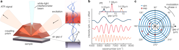
As sketched in Fig. 1 (a), the top of a conventional isosceles triangular prism is grounded off parallel to the probing interface. A fiber coupled white-light beam is fed through the prism top and focused onto the sample with opening angle. Reflections from the prism-air interface and the air-sample interface are fed back to the fiber coupler. The divergence of the white-light is small enough such that the Rayleigh length is much larger than the coupling gap and both contributions can interfere in the far-field. For detection of the interference signal, the back-reflected signal is passed through a beam splitter to separate the forward and backward propagating signals. A significant part of the light is reflected back from the fiber end due to coupling losses. This can be counteracted by placing a pair of crossed polarizers in the beam path, ensuring that only light coming out of the non-polarization-maintaining fiber can reach the spectrometer. Alternatively, a bifurcated fiber bundle has been used to split the in and outgoing white-light (Thorlabs RP21). The white-light signal is analyzed in a UV/VIS spectrometer (Thorlabs CCS200) for the quartz prism setup, and an InGaAs array based spectrometer (Ocean Optics NIRQuest512) for the KRS5 prism, respectively.
The light for polariton excitation, on the other hand, is incident and reflected at the bottom of the prism at angles above total internal reflection. Due to this angular separation, the gap width can be measured simultaneously to the reflectance spectrum featuring the polariton resonances (see Fig. 1(a)).
The detectable range for the distance readout depends on the signal-to-noise ratio and the wavelength resolution of the spectrometer. The former limits the lower end of the range where the modulation period becomes wider than the spectrum. The latter becomes the limiting factor when the modulation period approaches the spectrometer resolution, which happens at the upper end of the range. For the presented VIS setup, detectable gaps span almost 3 orders of magnitude between and , while the NIR setup covers a range from up to . For small gap sizes precise angular adjustment is mandatory. For sample sizes in the millimeter range angular adjustment of a few arcsecond is required to prevent the collision of sample and prism.
The back reflected white-light signal carries a distance dependent spectral modulation. The actual gap width can be calculated from this unambiguous signature. The condition for constructive interference from the two surfaces is
| (1) |
where is the interface spacing, the refractive index in the gap, the tilt angle of the white-light beam with respect to the sample surface normal, and represents the phase retardation due to reflection at the sample surface. Light reflected at the prism surface is in-phase with the incident wave ( as required by ATR spectroscopy). At the sample surface, however, the phase retardation depends on the absorption in the medium and can be between and , as illustrated in Fig. 1 (a). Since metals supporting SPPs are absorptive in the spectral region of the white-light source, knowing is essential, while in non-absorptive dielectrics supporting SPhPs the phase retardation can be neglected. Although the influence of does not alter the periodicity of the signal with distance, it does give an offset which is important for the absolute distance. Disregarding is likely the reason why previous experiments on the Otto ATR geometry have underestimated the critical coupling distanceFalge and Otto (1973); Futamata et al. (1994). Consequently, the reflection phase has to be known or measured by ellipsometry prior to calculating the gap from the reflectance spectrum. In Fig. 1 (b), exemplary spectra are shown after referencing the data to a spectrum taken at a gap width , i.e. far above the resolvable coherence length.
The calculation of the gap width from the spectral data can be performed with a Fourier transformation. For this means, the peak position in the Fourier spectrum is evaluated as follows:
| (2) |
Where the left hand side is the optical path length of the light in the gap and the right hand side is composed of two influences on the spectral modulation pattern: Firstly, the modulation frequency resulting from spacing of the two interfaces, and secondly the dispersion of the reflection phase , being non-zero for absorbing materials where resonances alter the reflection phase. There are two ways to handle this dispersion when computing by means of a Fourier transform. If a material resonance lies outside the spectral window and the phase is relatively flat, it can be approximated with a linear slope, which gives a constant offset to the measurement (). For materials with a nonlinear reflection phase or multiple resonances inside the reflectivity spectrum it is suggested that the phase is precompensated before applying the Fourier transform. This can be achieved by multiplying the modulation signal with .
Additional improvement is gained by evaluating not only the frequency but also the phase of the modulation. Fig. 1 (c) shows a polar plot with the frequency on the radial axes and the corresponding phase in azimuthal direction. In this representation, a changing gap leads to a spiral around the origin. Especially for very narrow gaps with few or even single cycle modulation, evaluation of the phase significantly improves the accuracy.
Besides absolute gap width readout, our method allows for parallel alignment of prism and sample with high accuracy (). This is achieved by firstly optimizing the contrast of the interference signal, and secondly by laterally scanning the white-light measurement spot over the sample. By this means, the obtained constant gap width assures constant polariton excitation conditions across the complete light spot, being crucial for obtaining well-defined polariton resonances in the ATR spectra.
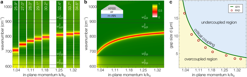
In order to demonstrate our method, we present a measurement of critically coupled SPhPs excited in m-cut hexagonal aluminum nitride (AlN) in the KRS5 prism setup. In Fig. 2 (a), the reflectance data taken at 8 different angles of incidence is plotted, where the dips in the reflectance (red spots) correspond to the excitation of a SPhP. Clearly, this excitation frequency shifts with varying in-plane momentum (), following the characteristic shape of the SPhP dispersion at a single interfaceRaether (1988). Fig. 2 (b) shows the corresponding theoretical reflectance signal that was calculated with an anisotropy-aware transfer matrix methodPassler and Paarmann (2017). The SPhP dispersion branch which is visible between and is in excellent agreement with our experimental results. We note that while the excitation of a SPhP at critical coupling conditions ideally leads to zero reflectance, we here observe dips with non-zero minimum reflectance due to the finite spectral width of our excitation source (see Supplementary Information for details).
The air gap of critical coupling conditions , i.e. where the SPhP is excited most efficiently resulting in minimized reflectancePassler et al. (2017), strongly depends on the in-plane momentum, as shown in Fig. 2 (c) (green solid line). Therefore, the air gap has to be adjusted in the experiment at each incidence angle individually, optimizing for the deepest dip in the reflectance. These experimental critical gaps are plotted as red circles in Fig. 2 (c), following the theoretically calculated curve (green solid line). The origin of the systematic offset is explained in the Supplementary Information. Note that for deviations from the curve of critical coupling, the SPhP excitation looses efficiency either because of large radiative losses into the prism at close gaps (overcoupled region), or because of insufficient overlap with the evanescent wave from the prism at large gaps (undercoupled region).
The critical gap markes the point where the radiative losses equal the intrinsic lossesNeuner et al. (2009) and is hence a function of the propagation lifetime of the SPhP. It can vary strongly for different materials or even for different polaritons in a single systemPassler and Paarmann (2017). Therefore, it is essential to have precise control over the gap in order to excite polaritons under critical coupling conditions and to map out their dispersion curves. Measurements with air gaps down to – as required for surface plasmon polariton excitation – are shown in the Supplementary Information, featuring the quartz prism setup.
In summary, the feasibility of white-light-based interferometry for surface polariton excitations was demonstrated experimentally with an m-cut hexagonal AlN sample. The method has proven to be a useful tool for the precise control over the evanescent coupling strength by providing live feedback of the coupling gap without disturbing the polariton excitation. The gained control over the air gap was employed to achieve critical coupling conditions at any in-plane momentum, hence allowing to experimentally reconstruct the SPhP dispersion of the AlN sample. The results were verified with theoretical calculations showing an excellent agreement.
The resolution limit of our method is determined by external parameters like the spectrometer resolution, the wavelength calibration, and ellipsometry data of the materials involved, and is therefore further extendable. Given that the reflectivity spectrum can be measured with high precision, the dispersion of the reflection phase is left as the largest source of error when determining . Here, the accuracy of the ellipsometry data is important, when single digit nanometer resolution is required. As a guide we have estimated for a Au surface in the visible region by comparing available ellipsometry dataJohnson and Christy (1972); Palik (1998); Gao, Lemarchand, and Lequime (2012); Babar and Weaver (2015). This has led to an uncertainty of . In comparison, Au film samples that were coated in the same batch and measured individually with spectral ellipsometry resulted in an error of less than . Completely disregarding the influence of the reflection phase dispersion would result in an error as large as for Au.
The range of to as obtained in our setup should cover the majority of applications for both SPPs and SPhPs. Another advantage of our method is the spatial and galvanic isolation provided by the fiber connection between the sensing head and the detection system, which enables functionality under a broad range of measurement conditions. Furthermore, applications in nonlinear optics can benefit from the real-time feedback to stabilize the coupling even under strong temperature drifts, as happens when tuning the frequency from off-resonance to on-resonance excitation of the polariton. Finally we emphasize that the presented method is not limited to surface polariton propagation but has various other potential applications where well-defined air-gap based evanescent coupling is required. Among others, this includes ATR-spectroscopy, waveguide coupling or excitation of ring-resonator structures.
In conclusion, we have presented a method to overcome technical challenges in air-coupled Otto geometry setups. Our technique allows angle resolved spectroscopy with constant critical coupling conditions, thus granting the possibility to experimentally determine polariton dispersions of any flat sample. Furthermore, tuning the coupling gap allows critical coupling for a large wavelength range compared with systems that are optimized for a fixed wavelength such as grating couplers or Kretschmann geometries. Quantifying the coupling gap not only assures repeatability and comparability but can also serve to measure propagation losses from previously unknown or uncharacterized samples. By providing the necessary control over polariton coupling with tunable air gap in a reliable and widely applicable manner, we hence envision our method to pave the way for multiple future studies in the field of polaritonic nanophotonics.
I Supplementary Material
Details on the experimental procedure and the free-electron laser (S1), details on the fitting procedure for the ATR data (S2), and details of the quartz prism setup for VIS and NIR excitation (S3).
II Acknowledgement
This work was supported by the German Research Foundation under grant WO 477/35-1. The authors thank J.D. Caldwell (Vanderbilt University) for providing the AlN sample.
References
- Bergh, Kotler, and Shaw (1980) R. A. Bergh, G. Kotler, and H. J. Shaw, Electronics Letters 16, 260 (1980).
- Betzig et al. (1986) E. Betzig, A. Lewis, A. Harootunian, M. Isaacson, and E. Kratschmer, Biophysical Journal 49, 269 (1986).
- Axelrod (1981) D. Axelrod, The Journal of Cell Biology 89, 141 (1981).
- Homola (2003) J. Homola, Analytical and bioanalytical chemistry 377, 528 (2003).
- Beaglehole (1969) D. Beaglehole, Physical Review Letters 22, 708 (1969).
- O’Hara, Averitt, and Taylor (2004) J. F. O’Hara, R. D. Averitt, and A. J. Taylor, Optics Express 12, 6397 (2004).
- Caldwell et al. (2013) J. D. Caldwell, O. J. Glembocki, Y. Francescato, N. Sharac, V. Giannini, F. J. Bezares, J. P. Long, C. Owrutsky, I. Vurgaftman, J. G. Tischler, V. D. Wheeler, N. D. Bassim, L. M. Shirey, R. Kasica, and S. a. Maier, Nano Letters 13, 3690 (2013).
- Wang et al. (2013) T. Wang, P. Li, B. Hauer, D. N. Chigrin, and T. Taubner, Nano Letters 13, 5051 (2013).
- Huber et al. (2005) A. Huber, N. Ocelic, D. Kazantsev, and R. Hillenbrand, Applied Physics Letters 87 (2005).
- Li et al. (2015) P. Li, M. Lewin, A. V. Kretinin, J. D. Caldwell, K. S. Novoselov, T. Taniguchi, K. Watanabe, F. Gaussmann, and T. Taubner, Nature Communications 6, 7507 (2015).
- Fleming (2013) A. J. Fleming, Sensors and Actuators A: Physical 190, 106 (2013).
- Otto (1968) A. Otto, Zeitschrift für Physik 216, 398 (1968).
- Passler et al. (2017) N. C. Passler, I. Razdolski, S. Gewinner, W. Schöllkopf, M. Wolf, and A. Paarmann, ACS Photonics 4, 1048 (2017).
- Grosse et al. (2018) N. B. Grosse, P. Franz, J. Heckmann, K. Pufahl, and U. Woggon, Phys. Rev. A 97, 043844 (2018).
- Passler and Paarmann (2017) N. C. Passler and A. Paarmann, Journal of the Optical Society of America B 34, 1 (2017).
- Falge and Otto (1973) H. J. Falge and A. Otto, Physica Status Solidi (B) 56, 523 (1973).
- Futamata et al. (1994) M. Futamata, P. Borthen, J. Thomassen, D. Schumacher, and A. Otto, Applied Spectroscopy 48, 252 (1994).
- Raether (1988) H. Raether, Springer-Verlag, New York 111, 136 (1988).
- Neuner et al. (2009) B. Neuner, D. Korobkin, C. Fietz, D. Carole, G. Ferro, and G. Shvets, Optics letters 34, 2667 (2009).
- Johnson and Christy (1972) P. B. Johnson and R. W. Christy, Physical Review B (1972), 10.1103/PhysRevB.6.4370, arXiv:arXiv:1011.1669v3 .
- Palik (1998) E. D. Palik, Unknown Journal (1998) arXiv:978-0-12-544415-6 .
- Gao, Lemarchand, and Lequime (2012) L. Gao, F. Lemarchand, and M. Lequime, Optics Express (2012), 10.1364/OE.20.015734.
- Babar and Weaver (2015) S. Babar and J. H. Weaver, Applied Optics (2015), 10.1364/AO.54.000477.