Matter-wave interferometry using a levitated magnetic nanoparticle
Abstract
The superposition principle is one of the bizarre predictions of quantum mechanics. Nevertheless, it has been experimentally verified using electrons, photons, atoms, and molecules. In this article, using a nm levitated ferromagnetic FePt nanoparticle, an exotic all optical spin polarization technique and the matter-wave interferometry, we show that a mesoscopic spatial Schrodinger cat can be created. Additionally, we argue that the maximum spatial separation between the delocalized wavepackets can be and is significantly larger than the object itself.
1 Introduction
Quantum mechanics prescribes [1] that, irrespective of their size or mass, an object can be in multiple states at once and this is certainly true for microscopic systems [2, 3, 4, 1, 5]. Specifically, in the past, the quantum superposition principle has been demonstrated using neutrons [6], electrons [1], ions [2] and molecules [3, 4]. In 1996, Monroe et al. created a spatial Schrodinger cat state in which they put a beryllium ion in two different spatial locations separated by 80 nm at the same time [2]. The size of the beryllium ion was approximately nm in size (kg). In another experiment [5], oligoporphyrins molecules with high kinetic energy were sent through different grating structures and the resulting matter-wave interfered after a free flight due to the wave nature of matter. In this case, the wave packet of oligoporphyrins was delocalized by nm. The current record for the largest spatial superposition is m which was realized using a Bose-Einstein condensate of Rubidium atoms in an atomic fountain [7], while the heaviest object so far put into a superposition state is about kg [5].
Increasing the macroscopicity of a spatial superposition state is an ongoing global effort and many proposals have been put forward using clamped and levitated optomechanical systems [8, 9, 10, 11, 12, 13, 14, 15]. In these schemes the spatial separations between the two arms of the superposed states are less than the size of the respective objects (nm ). Nevertheless, a successful experimental demonstration of such a state using a mesoscopic system can resolve the apparent conflict between quantum mechanics and general relativity [1]. A demonstration of the quantum superposition principle using a mesoscopic object can also shed light on the gravity’s role on the quantum state reduction [16] and test different wavefunction collapse models [17, 18].
In this article, we theoretically show that the spatial separation of a quantum superposed state can be increased significantly by using existing technologies. To achieve this, we exploit recent progress, the optical spin polarization of ferrimagnetic or ferromagnetic materials [19, 20]. In particular, we use all optical helicity dependent switching for flipping spin states of ferrimagnetic or ferromagnetic materials at cryogenic temperature. Exploiting this helicity dependent spin polarization, a pragmatic magnetic field gradient, and a levitated nanosphere, we show that, in principle, a separation of at least between the delocalized superposed states can be achieved.
2 Spatial superposition
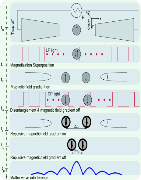
A schematic of the proposed experiment and the sequence of events required to create the spatial superposition are shown in Fig. 1. In the proposed scheme, a single domain ferromagnetic or ferrimagnetic particle is levitated using an ion trap at a cryogenic temperature of mK [21, 22, 23, 24, 25]. Other platforms of levitation include magnetogravitational, optical and magnetic trap [26, 27, 28, 29, 30, 31]. Spins in a single domain ferrimagnetic or ferromagnetic nanoparticle are strongly interacting, highly correlated and perfectly ordered in the ground state due to the strong exchange coupling among the electrons [32, 33]. Consequently, the spins of a small single domain ferrimagnet or ferromagnet can be considered as a single superspin and can be described using magnetization [32, 34, 33, 35], where the Lande factor, is the Bohr magneton and is the total uncompensated spin. After levitation, the centre of mass (CM) temperature of the nanoparticle is reduced down to a suitable temperature for a better visibility in the matter-wave interferometry [24, 21]. Here, the motional ground state of the particle is ideal but not necessary (see below).
Once the required CM temperature is achieved, the ion trap is switched off in such a way that the particle remains unperturbed. Subsequently, using all-optical helicity dependent switching (AOHDS), a superposition of magnetization (spin) is created. Specifically, it has been demonstrated that the magnetization of certain ferrimagnetic (GdFeCo) and ferromagnetic (FePt,CoPt) thin films, composed of many domains, change from a down (up ) polarized state to an up (down ) polarized state when exposed to a femtosecond right (left ) circularly polarized light. In contrast, when the same film is exposed to linearly polarized light () pulses, the magnetization of each domain becomes either up or down polarized at random [20, 36, 37, 38]. In another word, linearly polarized light creates a superposition of all up and all down spin states but the superposition collapses to one of the eigenstates - possibly due to the simultaneous measurements that these experiments undertake to determine the effect of the laser pulse on the magnetic film.
Although the exact mechanism behind AOHDS is not clearly understood yet [39, 40], the combined effect of the laser induced heating and the effective magnetic field associated with the laser pulse, the inverse Faraday effect, and an enhanced spin-orbit coupling are among the mechanisms believed to be responsible for this phenomenon [20, 40, 39]. In a later experiment [19], it has been demonstrated that AOHDS works better at a cryogenic temperature. Indeed, it has been shown that a lower laser fluence than the original room temperature experiment [20] is sufficient to change the spin state. Additionally, in these experiments [20, 36, 37, 38], it has been found that the number of photons required is significantly less than the number of spin flipped [20, 19]. For example, in the first experiment [20], the number of photons used to flip spins in film was . This also negates the possibility of a spin flip due to a single photon absorption.
To create a spatial superposition, once the ion trap has been switched off and a spin superposition has been created, an inhomogeneous dc magnetic field [41] is activated at time and the particle evolves under the influence of gravitational and magnetic fields for a suitable time (see Fig. 1). The spatial separation [13, 15] between the two arms of a superposed states after time is
| (1) |
where is the magnetization of the particle, is the spin projection along the quantization axis (axis), is the Lande factor and is the Bohr magneton. is the magnetic field gradient and is the mass of the levitated particle.
Detection: After the desired separation between the superposed states is achieved, where and are the spatial states at position and , respectively, a disentangling circularly polarized light pulse is activated and the initial magnetic field gradient is switched off. A right (left) circularly polarized light pulse reduces a superposed state into an up (down) spin state. The state of the system at this stage is . Note that once the spin superposition has been reduced to one of the eigenstates via the disentangling operation, the experiment is no longer limited by the finite spin coherence time. Instead, the experiment is restricted by the centre-of-mass coherence time which can be very long in ultra high vacuum [42]. Incidently, a cryogenic experimental condition, as aimed in this proposal, inherently provides this level of vacuum [23] and hence a long motional coherence time is naturally guaranteed. Nevertheless, to reduce the free evolution time, at this stage of the experiment, a new inhomogeneous dc magnetic field is activated which redirects the separated wave packets towards the centre. Once the wavepackets approach each other from opposite directions, the polarity of the magnetic field is changed which decelerates the wavepackets. Note that the pulsed operation of a dc electromagnet with ns pulse has been recently demonstrated [41]. After waiting for an adequate time when the terminal velocities of the wavepackets approach zero, the magnetic field is switched off. Subsequently, at the centre, the two wavepackets interfere to produce an interference pattern. Specifically, let the two arms of the superposed states evolve in free space for an additional time . After this free flight, the two arms of the matter-wave interfere [3, 11, 12] on a substrate just like in Young’s double slit experiment. Overall, the sequence of events described above is repeated many times to reveal the fringe pattern. Eventually, this interference pattern is used as the signature of the spatial superposition created. The period of the interference pattern [11] is given by , where is the mass of the particle and are the positions of the wavepackets when their velocities were zero.
3 Results and discussion
The visibility of the matter-wave fringe pattern depends on, among other factors, the position uncertainty of the levitated nanoparticle before the ion trap is switched off. An uncertainty in the position translates into an uncertainty of . Here, the motional ground state of the particle can be useful. However, it is not necessary as long as , where is the particle’s instantaneous position. This seems readily achievable given the sub-kelvin ambient temperature and the ultra high vacuum that the cryogenic environment provides [23]. Additionally, due to the small particle size (nm radius) considered in this article, the secular frequency of the oscillator [25] can be significantly higher than usual [25] which naturally leads to a lower uncertainty in the position. Here, is the number of elementary charge and is the magnitude of the electronic charge. and are the amplitude and the frequency of the applied ac voltage. is the distance of the trap centre from the electrodes and is the mass of the particle. For example, for , kg, mm, kHz and V, one gets kHz. For mK, we find nm. This is significantly lower than nm (see below). Hence, the visibility of the fringe pattern is robust against the uncertainty in the position. Radiation pressure, originated from the laser pulse used in the creation of spin superposition, can be significant. For an estimate, if we consider photons (actual number can be different) approximately required for about spins in particle then the resultant velocity of the particle due to photon recoil is or equivalently mK. This is not negligible. However, this is a deterministic effect and hence cannot reduce the visibility of the interference fringe but can shift the fringe pattern away from the centre. This can be compensated by using magnetic fields of different amplitude from each side in the last step (see Fig. 1). Polydispersity of nanoparticles, responsible for different de Broglie wavelengths, is another factor which can reduce the visibility of the fringe pattern. Fortunately, nanoparticles used in this proposal (FePt) have been synthesized in monodisperse configuration [43] and consequently, the current scheme is robust.
Spin coherence time: One of the main requirements of this experiment is the coherence of many spins contained in a ferromagnetic nanoparticle. Spin coherence time is characterized by using two time constants i.e. the spin-lattice relaxation time and the transverse relaxation time , and in general [44]. While is determined by the spin-lattice interaction, is primarily fixed by the inhomogeneities and fluctuation in magnetic and crystal fields. For homogeneous isotropic material [44, 45]. In ferromagnetic materials, the usage of and is not prevalent rather Gilbert damping , which characterizes how a spin system loses energy and angular momentum, is widely used [46, 47, 48]. Nevertheless, , and are intricately related with each other [49, 48]. In the absence of inhomogeneities, valid for small nanocrystals, coherence time is given by [49], where is the magnetic field and is the gyromagnetic ratio. In bulk FePt sample, has been measured [50, 51]. Since a single domain nm FePt nanocrystal is considered in this article, a smaller and hence a longer coherence time can be expected. Levitation, a physical contactless low noise environment, may boost the coherence time further. Additionally, performing the experiment at a subkelvin temperature will increase the coherence time significantly. A cryogenic temperature is also beneficial for suppressing magnons [52] which is another mechanism that shortens the coherence time. It is also important to mention that due to the finite size of the magnetic nanoparticles considered in this article, propagating magnons will be heavily damped and only the high energy oscillations can be excited [33].
Example: Although all optical helicity dependent switching has been demonstrated using many different materials, in this proposal we use crystalline ferromagnetic face centred tetragonal (L10) FePt. It has one of the highest magnetocrystalline anisotropy and is readily available in monodisperse single domain nanocrystalline form [43]. All optical helicity dependent switching using a granular film of FePt nanoparticles has also been recently demonstrated [38] using this material. Ferromagnetism, a manifestation of quantum exchange coupling, of FePt guarantees that all the spins contained within a levitated particle are exchange-coupled and hence behave as a single coherent macrospin. FePt is also preferable due to most of the naturally abundant isotopes of iron () and platinum () are nuclear spin free which guarantees enhanced spin coherence time [45, 44].
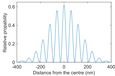
To provide an example, let us consider a FePt particle of radius nm levitated and prepared in spatial superposition as described before. Assuming a saturation magnetization [50] with and is the volume of the particle, [41], kg m-3 and s, one gets . This is a macroscopic distance. Note that the spin coherence time used in this calculation is an estimate only. In fact, a measured value of the spin coherence time of FePt is not available in literature. In retrospect, measuring the spin coherence time of a ferromagnetic nanoparticle will be of great interest for many applications. Figure 2 shows the relevant matter-wave interference pattern [11] after the free evolution of the wavepackets for ms. The period of this fringe pattern is nm and can be changed by controlling . can be made larger by having a longer but this will increase the physical size () of the experiment, where is the gravitational acceleration. The interference pattern can be post processed using an electron microscope to physically reveal the spatial superposition created. This, however, cannot show the maximum spatial separation that the current scheme can produce. For that, in some run of the experiment, one can perform measurements just before the disentangling pulse is applied (see Fig. 1). Off-course this will collapse the wavefunction. But this is essential to reveal the advantage of the current scheme.
Macroscopicity: In the scale of macroscopicity [53], the combination of the particle mass and the spin coherence time used in the previous example amount to , where is the fringe visibility, is the mass of the object, is the spin coherence time and is the electronic mass. In the calculation, we have used . At present the state of the art experiment has [5].
4 Conclusions
We have theoretically shown that using a levitated single domain magnetic nanoparticle and all optical helicity dependent switching, a spatial superposition state can be created. In this scheme, the spatial separation between the two arms of a superposition state is . This is significantly larger than the actual object put into the superposition. However, there are significant experimental challenges to overcome. One such challenge is the creation of the spin superposition using the all optical helicity dependent switching. While many experiments have demonstrated this phenomenon in the classical context, it remains to be seen in the quantum realm. Likewise, the spin coherence time in ferromagnetic systems containing many spins has not been measured yet. Indeed, measuring the spin coherence time in these systems will itself be very interesting. This can potentially open up many new applications in spintronics and other spin based systems.
References
- Arndt and Hornberger [2014] M. Arndt and K. Hornberger. Testing the limits of quantum mechanical superpositions. Nat. Phys., 10(4):271–277, 2014.
- Monroe et al. [1996] C. Monroe, D. M. Meekhof, B. E. King, and D. J. Wineland. A “schrödinger cat” superposition state of an atom. Science, 272(5265):1131–1136, 1996. doi: 10.1126/science.272.5265.1131.
- Arndt et al. [1999] M. Arndt, O. Nairz, J. Vos-Andreae, C., G. Van Der Zouw, and A. Zeilinger. Wave–particle duality of c60 molecules. Nature, 401(6754):680–682, October 1999.
- Eibenberger et al. [2013] S. Eibenberger, S. Gerlich, M. Arndt, M. Mayor, and J. Txen. Matterwave interference of particles selected from a molecular library with masses exceeding 10000 amu. Phys. Chem. Chem. Phys., 15:14696–14700, 2013.
- Fein et al. [2019] Y. Fein, P. Geyer, P. Zwick, F. Kiałka, S. Pedalino, M. Mayor, S. Gerlich, and M. Arndt. Quantum superposition of molecules beyond 25 kda. Nat. Phys., 15(12):1242–1245, 2019.
- Zawisky et al. [2002] M. Zawisky, M. Baron, R. Loidl, and H. Rauch. Testing the world’s largest monolithic perfect crystal neutron interferometer. Nucl. Instrum. Methods Phys. Res., 481(1):406–413, 2002.
- Kovachy et al. [2015] T. Kovachy, P. Asenbaum, C. Overstreet, C. A. Donnelly, S. M. Dickerson, A. Sugarbaker, J. M. Hogan, and M. A. Kasevich. Quantum superposition at the half-metre scale. Nature, 528:530–533, 2015.
- Bose et al. [1999] S. Bose, K. Jacobs, and P. L. Knight. Scheme to probe the decoherence of a macroscopic object. Phys. Rev. A, 59:3204–3210, 1999.
- Marshall et al. [2003] W. Marshall, C. Simon, R. Penrose, and D. Bouwmeester. Towards quantum superpositions of a mirror. Phys. Rev. Lett., 91:130401, Sep 2003.
- Romero-Isart et al. [2011] O. Romero-Isart, A. C. Pflanzer, F. Blaser, R. Kaltenbaek, N. Kiesel, M. Aspelmeyer, and J. I. Cirac. Large quantum superpositions and interference of massive nanometer-sized objects. Phys. Rev. Lett., 107:020405, Jul 2011. doi: 10.1103/PhysRevLett.107.020405.
- Yin et al. [2013] Z. Yin, Tongcang Li, Xiang Zhang, and L. Duan. Large quantum superpositions of a levitated nanodiamond through spin-optomechanical coupling. Phys. Rev. A, 88:033614, Sep 2013.
- Bateman et al. [2014] J. Bateman, S. Nimmrichter, K. Hornberger, and H. Ulbricht. Near-field interferometry of a free-falling nanoparticle from a point-like source. Nat. Commun., 5(1), 2014. ISSN 2041-1723.
- Wan et al. [2016] C. Wan, M. Scala, G. W. Morley, A. T. M. Anishur Rahman, H. Ulbricht, J. Bateman, P. F. Barker, S. Bose, and M. S. Kim. Free nano-object ramsey interferometry for large quantum superpositions. Phys. Rev. Lett., 117:143003, Sep 2016.
- Romero-Isart [2016] O. Romero-Isart. Coherent inflation for large quantum superpositions of microspheres. N. J. Phys., 19(12), 2016.
- Rahman [2019] A T M Anishur Rahman. Large spatial schrodinger cat state using a levitated ferrimagnetic nanoparticle. New J. Phys., 21, oct 2019.
- Penrose [1996] R. Penrose. On gravity’s role in quantum state reduction. Gen. Rel. Gravit., 28(5):581–600, 1996.
- Bassi et al. [2013] A. Bassi, K. Lochan, S. Satin, T. P. Singh, and H. Ulbricht. Models of wave-function collapse, underlying theories, and experimental tests. Rev. Mod. Phys., 85(2):471–527, 2013.
- Carlesso and Donadi [2019] M. Carlesso and S. Donadi. Collapse models: Main properties and the state of art of the experimental tests. In Bassano Vacchini, Heinz-Peter Breuer, and Angelo Bassi, editors, Advances in Open Systems and Fundamental Tests of Quantum Mechanics, pages 1–13, 2019.
- Hohlfeld et al. [2009] J. Hohlfeld, C. D. Stanciu, and A. Rebei. Athermal all-optical femtosecond magnetization reversal in gdfeco. Appl. Phys. Lett., 94(15):152504, 2009.
- Stanciu et al. [2007] C. D. Stanciu, F. Hansteen, A. V. Kimel, A. Kirilyuk, A. Tsukamoto, A. Itoh, and Th. Rasing. All-optical magnetic recording with circularly polarized light. Phys. Rev. Lett., 99:047601, Jul 2007. doi: 10.1103/PhysRevLett.99.047601.
- Alda et al. [2016] I. Alda, J. Berthelot, R. A. Rica, and R. Quidant. Trapping and manipulation of individual nanoparticles in a planar paul trap. Appl. Phys. Lett., 109(16):163105, 2016.
- Huillery et al. [2019] P. Huillery, T. Delord, L. Nicolas, M. Van Den Bossche, M. Perdriat, and G. Hétet. Spin-mechanics with levitating ferromagnetic particles. arXiv:1903.09699, 2019.
- Vinante et al. [2019] A. Vinante, A. Pontin, M. Rashid, M. Toroš, P. F. Barker, and H. Ulbricht. Testing collapse models with levitated nanoparticles: Detection challenge. Phys. Rev. A, 100:012119, Jul 2019.
- Bykov et al. [2019] D. S. Bykov, L. Dania, P. Mestres, and T. E. Northup. Laser cooling of secular motion of a nanoparticle levitated in a Paul trap for ion-assisted optomechanics. In Kishan Dholakia and Gabriel C. Spalding, editors, Optical Trapping and Optical Micromanipulation XVI, volume 11083, pages 78 – 83. International Society for Optics and Photonics, SPIE, 2019. doi: 10.1117/12.2528141. URL https://doi.org/10.1117/12.2528141.
- Bullier et al. [2020] N P Bullier, A Pontin, and P F Barker. Characterisation of a charged particle levitated nano-oscillator. J. Phys. D, 53(17):175302, feb 2020. doi: 10.1088/1361-6463/ab71a7. URL https://doi.org/10.1088%2F1361-6463%2Fab71a7.
- Gieseler et al. [2019] J. Gieseler, A. Kabcenell, E. Rosenfeld, J. D. Schaefer, A. Safira, M. J. A. Schuetz, C. Gonzalez-Ballestero, C. C. Rusconi, O. Romero-Isart, and M. D. Lukin. Single-spin magnetomechanics with levitated micromagnets. arXiv:1912.10397, 2019. doi: 10.1088/1367-2630/aacac1. URL https://doi.org/10.1088%2F1367-2630%2Faacac1.
- Vinante et al. [2020] A Vinante, P Falferi, G Gasbarri, A Setter, C Timberlake, and H Ulbricht. Ultralow mechanical damping with meissner-levitated ferromagnetic microparticles. arXiv:1912.12252, 2020.
- Slezak et al. [2018] B. R Slezak, C. W Lewandowski, J. F. Hsu, and B. D’Urso. Cooling the motion of a silica microsphere in a magneto-gravitational trap in ultra-high vacuum. New J. Phys., 20(6):063028, jun 2018. doi: 10.1088/1367-2630/aacac1. URL https://doi.org/10.1088%2F1367-2630%2Faacac1.
- Rahman and Barker [2017] A. T. M. Anishur Rahman and P. Barker. Laser refrigeration, alignment and rotation of levitated yb:ylf nanocrystals. Nature Photon, 11(10):634–638, October 2017.
- Seberson et al. [2019] T Seberson, Jonghoon Ahn, Jaehoon Bang, Tongcang Li, and F Robicheaux. Optical levitation of a yig nanoparticle and simulation of sympathetic cooling via coupling to a cold atomic gas. arXiv:1910.05371, 2019.
- Rahman and Barker [2020] A. T. M. Anishur Rahman and P. F. Barker. Optical levitation using broadband light. arXiv:2002.04650, 2020.
- Awschalom et al. [1992] D. D. Awschalom, D. P. DiVincenzo, and J. F. Smyth. Macroscopic quantum effects in nanometer-scale magnets. Science, 258(5081):414–421, 1992. doi: 10.1126/science.258.5081.414.
- Tabuchi et al. [2014] Y. Tabuchi, S. Ishino, T. Ishikawa, R. Yamazaki, K. Usami, and Y. Nakamura. Hybridizing ferromagnetic magnons and microwave photons in the quantum limit. Phys. Rev. Lett., 113:083603, Aug 2014.
- Chudnovsky and Friedman [2000] E. M. Chudnovsky and J. R. Friedman. Macroscopic quantum coherence in a magnetic nanoparticle above the surface of a superconductor. Phys. Rev. Lett., 85:5206–5209, Dec 2000.
- Rusconi et al. [2017] C. C. Rusconi, V. Pöchhacker, K. Kustura, J. I. Cirac, and O. Romero-Isart. Quantum spin stabilized magnetic levitation. Phys. Rev. Lett., 119:167202, Oct 2017. doi: 10.1103/PhysRevLett.119.167202.
- Lambert et al. [2014] C-H. Lambert, S. Mangin, B. S. D. Ch. S. Varaprasad, Y. K. Takahashi, M. Hehn, M. Cinchetti, G. Malinowski, K. Hono, Y. Fainman, M. Aeschlimann, and E. E. Fullerton. All-optical control of ferromagnetic thin films and nanostructures. Science, 345(6202):1337–1340, 2014. doi: 10.1126/science.1253493.
- Mangin et al. [2014] S. Mangin, M. Gottwald, C-H. Lambert, D. Steil, V. Uhlíř, L. Pang, M. Hehn, S. Alebrand, M. Cinchetti, G. Malinowski, Y. Fainman, M. Aeschlimann, and E. E. Fullerton. Engineered materials for all-optical helicity-dependent magnetic switching. Nat. Mater., 13(3), February 2014.
- John et al. [2017] R. John, M. Berritta, D. Hinzke, C. Müller, T. Santos, H. Ulrichs, P. Nieves, J. Walowski, R. Mondal, O. Chubykalo-Fesenko, J. McCord, P. Oppeneer, U. Nowak, and M. Münzenberg. Magnetisation switching of fept nanoparticle recording medium by femtosecond laser pulses. Sci. Rep., 7(1):4114–4114, December 2017. ISSN 2045-2322.
- Hadri et al. [2017] M. S. El Hadri, M. Hehn, G. Malinowski, and S. Mangin. Materials and devices for all-optical helicity-dependent switching. J. Phys. D, 50(13):133002, 2017.
- Zhang et al. [2016] G. P. Zhang, T. Latta, Z. Babyak, Y. H. Bai, and T. F. George. All-optical spin switching: A new frontier in femtomagnetism – a short review and a simple theory. Mod. Phy. Lett. B, 30(21), 2016.
- Harrison et al. [2015] J. Harrison, Y. Hwang, O. Paydar, J. Wu, E. Threlkeld, J. Rosenzweig, P. Musumeci, and R. Candler. High-gradient microelectromechanical system quadrupole electromagnets for particle beam focusing and steering. Phys. Rev. Accel. Beams., 18:023501, Feb 2015.
- Chang et al. [2010] D. E. Chang, C. A. Regal, S. B. Papp, D. J. Wilson, J. Ye, O. Painter, H. J. Kimble, and P. Zoller. Cavity opto-mechanics using an optically levitated nanosphere. PNAS, 107(3):1005–1010, 2010. doi: 10.1073/pnas.0912969107.
- Sun et al. [2000] S. Sun, C. B. Murray, D. Weller, L. Folks, and A. Moser. Monodisperse fept nanoparticles and ferromagnetic fept nanocrystal superlattices. Science, 287(5460):1989–1992, 2000. doi: 10.1126/science.287.5460.1989.
- Žutić et al. [2004] I. Žutić, J. Fabian, and S. Das Sarma. Spintronics: Fundamentals and applications. Rev. Mod. Phys., 76:323–410, Apr 2004. doi: 10.1103/RevModPhys.76.323.
- Bloch [1946] F. Bloch. Nuclear induction. Phys. Rev., 70:460–474, Oct 1946.
- Beaujour et al. [2009] J. M. Beaujour, D. Ravelosona, I. Tudosa, E. E. Fullerton, and A. D. Kent. Ferromagnetic resonance linewidth in ultrathin films with perpendicular magnetic anisotropy. Phys. Rev. B, 80:180415, Nov 2009. doi: 10.1103/PhysRevB.80.180415.
- Schoen et al. [2016] M. Schoen, D Thonig, M. Schneider, T. Silva, H. Nembach, O Eriksson, O Karis, and J. Shaw. Ultra-low magnetic damping of a metallic ferromagnet. Nat. Phys., 12(9):839–842, 2016.
- Capua et al. [2017] A. Capua, C. Rettner, S. Yang, T. Phung, and S. S Parkin. Ensemble-averaged rabi oscillations in a ferromagnetic cofeb film. Nat. Commun., 8, 2017.
- Capua et al. [2015] A. Capua, S. Yang, T. Phung, and S. S. P. Parkin. Determination of intrinsic damping of perpendicularly magnetized ultrathin films from time-resolved precessional magnetization measurements. Phys. Rev. B, 92:224402, Dec 2015.
- Iihama et al. [2013] S. Iihama, S. Mizukami, N. Inami, T. Hiratsuka, G. Kim, H. Naganuma, M. Oogane, T. Miyazaki, and Y. Ando. Observation of precessional magnetization dynamics in l1 0 -fept thin films with different l1 0 order parameter values. Jpn. J. Appl. Phys, 52(7R):073002, 2013.
- Fuller et al. [2009] R O Fuller, G A Koutsantonis, and R L Stamps. An experimental investigation of dynamic behavior in fept systems. Journal of Physics: Condensed Matter, 21(12):124203, 2009.
- Coey [2009] J. M. D. Coey. Magnetism and magnetic materials. Cambridge University Press, Cambridge ; New York, 2009. ISBN 9780511685156.
- Nimmrichter and Hornberger [2013] S. Nimmrichter and K. Hornberger. Macroscopicity of mechanical quantum superposition states. Phys. Rev. Lett., 110:160403, Apr 2013. doi: 10.1103/PhysRevLett.110.160403.