Creep of Chiral Domain Walls
Abstract
Recent experimental studies of magnetic domain expansion under easy-axis drive fields in materials with a perpendicular magnetic anisotropy have shown that the domain wall velocity is asymmetric as a function of an external in plane magnetic field. This is understood as a consequence of the inversion asymmetry of the system, yielding a finite chiral Dzyaloshinskii-Moriya interaction. Numerous attempts have been made to explain these observations using creep theory, but, in doing so, these have not included all contributions to the domain wall energy or have introduced additional free parameters. In this article we present a theory for creep motion of chiral domain walls in the creep regime that includes the most important contributions to the domain-wall energy and does not introduce new free parameters beyond the usual parameters that are included in the micromagnetic energy. Furthermore, we present experimental measurements of domain wall velocities as a function of in-plane field that are well decribed by our model, and from which material properties such as the strength of the Dzyaloshinskii-Moriya interaction and the demagnetization field are extracted.
pacs:
75.60.Ch,75.70.Ak,75.70.Kw,75.78.FgIntroduction. — The interest in nanomagnetic materials has grown steadily since magnetic storage devices, such as the racetrack memory, were proposed as a new tool to meet the ever increasing demand for computer storage capacity Parkin et al. (2008); Moon et al. (2015); Allwood et al. (2005); Hayashi et al. (2008). For such applications the domain wall (DW) chirality is an important parameter as it affects the speed and direction of DW motion. The interfacial Dzyaloshinskii-Moriya-interaction (DMI) Dzyaloshinskii (1958); Moriya (1960) arises from perpendicular inversion asymmetry in the system and affects the DW chirality. Hence it is of paramount importance to be able to measure the magnitude of the DMI using a simple experimental method. The interfacial DMI is modeled as an effective field that lies in-plane (IP) and is always perpendicular to the domain wall (DW) normal, hence preferring a Néel wall Fert and Levy (1980). Superpositioning the DMI field with an externally applied IP magnetic field could provide means of measuring it. This has lead to a boom of experimental studies on DW dynamics under the influence of an IP magnetic field Je et al. (2013); Boulle et al. (2013); Lavrijsen et al. (2015); Jué et al. (2016); Vaňatka et al. (2015); Lau et al. (2016); Pellegren et al. (2017); Kim et al. (2017); Lau et al. (2018); Kim et al. (2018).
There are several regimes of DW dynamics, determined by the strength of the DW driving force compared to the pinning force. In the flow regime the driving force is significantly higher than the pinning force and in this regime IP magnetic fields and DMI is succesfully modeled by means of the Landau-Lifschitz-Gilbert equation Landau and Lifshitz (1955); Li and Zhang (2004); Thiaville et al. (2012). In the creep-regime however, the DW is considered to be mostly pinned and in local equilibrium and has a net displacement because the bias is assisted by thermal fluctuations.
The creep model was successfully implemented to interpret magnetic domain growth driven by an external magnetic field in the direction of the magnetization of one of the domains, resulting in the famous universal creep law for the DW velocity : Lemerle et al. (1998). When introducing a magnetic field perpendicular to the magnetization direction of the domains, a modification to this creep law was proposed: , where is the elasticity of the DW Je et al. (2013). This modification turned out to described the experimental finding well for small IP magnetic fields, but is not able to describe the high-field region Lavrijsen et al. (2015). Recent attempts to improve the theoretical model exposed the dispersive nature of the elasticity but compromised on universality as extra free parameters were introduced that do not occur in the micromagnetic energy functional. One example of such a parameter is the length scale of the DW segments over which the creep motion occurs. In previous theories for DW motion in the creep regime this length scale does not enter the prediction for the velocity. It is, however, treated as a free fit parameter in Ref. [Pellegren et al., 2017], which makes a direct comparison with experiment hard. Furthermore, chiral damping was proposed to explain the asymmetric component of the velocity profiles Jué et al. (2016); Kim and Lee (2016); Kim et al. (2017); Lau et al. (2018). We contend however that in the quasi-static creep regime dynamic effects such as chiral damping should not play a significant role.
In this paper we construct a theory for motion of chiral domain walls in the creep regime which does not involve the free parameters introduced in Ref. [Pellegren et al., 2017]. We use it to interpret our experimental data on the DW velocity as a function of the IP magnetic field. We show that our model allows for quantitative determination of the strength of the interfacial DMI from field-driven DW creep measurements.
Model. — In the regime where some elastic manifold is pinned stronger than the applied driving force, one can still obtain a net motion from the combined effects of driving forces, thermal fluctuations and elasticity. Such motion is called creep. The creep model has been used to successfully describe vortex dynamics in superconductors (for a review see Ref. [Blatter et al., 1994]). Based on this work Lemerle et al. have shown that a DW in a thin magnetic film with PMA can be modelled successfully within this creep framework Lemerle et al. (1998).
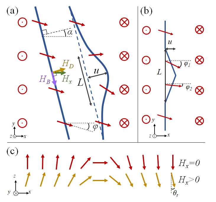
In Fig. 1 (a) the deformation of a DW due to a thermal fluctuation in the presence of an easy axis driving field is illustrated. If the size of the deformation is relatively small, the gained Zeeman energy from the driving field will be small relative to the elastic energy cost and the deformation cannot grow. But for increasing the Zeeman energy starts to dominate and deformations can grow. The deformations can be seen as nucleations whose chance of survival is determined by their size. For such a nucleation process, Arrhenius’ law tells us that the rate at which these surviving deformations will occur is determined by the height of the energy barrier (i.e. the free energy at the tipping point): Arrhenius (1889a, b).
Thus, to model the DW dynamics we need to determine the free energy of the DW segment as a function of and optimize it to find . The free energy is composed of the elastic energy cost and the Zeeman energy gain, which depend not only on , but also on the DW displacement : . To express in terms of we use Lemerle et al. (1998); Kardar and Nelson (1985); Fisher and Huse (1991), where is the Larkin length scale determined by minimizing the sum of the elastic and pinning energy density for , and is a proportionality constant. Hence, the next step is to determine the elastic energy to be able to compute and express , and thereby , in terms of .
The elastic energy is defined as the difference in internal, i.e. excluding pinning and driving, energy between the domain wall before and after the deformation. Naively this would just be given by the DW energy density times the added length due to the deformation, but due to the application of the external IP magnetic field the DW energy density itself depends on the orientation of the DW with respect to this applied field. Furthermore, the IP magnetization of the sample at the DW is affected by the exchange interaction. This induces an extra energy cost of bending the DW.
With these considerations in mind, only the elongation of the DW due to the deformation does not provide enough information; we need to know the shape of the deformation. Following Blatter et al. we model the deformation as an angular shape for simplicity, see Fig. 1 (b) Blatter et al. (1994). Note that Pellegren et al. chose an arc shape Pellegren et al. (2017), but did not implement the exchange energy cost due to the kink in the connection with the straight DW segments, resulting in unphysical divergences (as demonstrated in the Supplemental Material SM ) that do not occur in our theory.
As a first approximation we have chosen the IP magnetization of each separate segment to be constant and implement the bending energy cost as a nearest neighbor exchange interaction at the bending points. The energy of the system is then minimized (numerically) over the IP magnetization angle of the two segments.
We compute the energy density of the domain wall by inserting the domain-wall solution into the micromagnetic energy functional. For more details see the Supplemental Material SM . This yields for the energy per unit length and layer thickness of a straight domain wall:
| (1) |
The first term is the exchange interaction over , the DW thickness. The second term is the demagnetization energy, expressed in terms of the effective Bloch field (this energy favors a Bloch DW, hence the nomenclature), the angle between the DW normal and the -axis and the angle the IP magnetization at the DW with the direction of the IP magnetic field, see Fig. 1 (a). The third term is the Zeeman energy due to the applied IP magnetic field and the fourth is the DMI expressed in terms of an effective field favoring a Néel type DW. The prefactors involving incorporate the tilting in the -direction of the magnetic domains due to the external IP magnetic field (see Fig. 1 (c)). The functions and are given in the Supplemental Material SM .
Similarly, we obtain the Zeeman energy from the driving field
| (2) |
Again, the factor comes from the tilted domains as illustrated in Fig. 1 (c). By dividing out in Eqs. 1 and 2, the relevant dimensionless parameters become , , and .
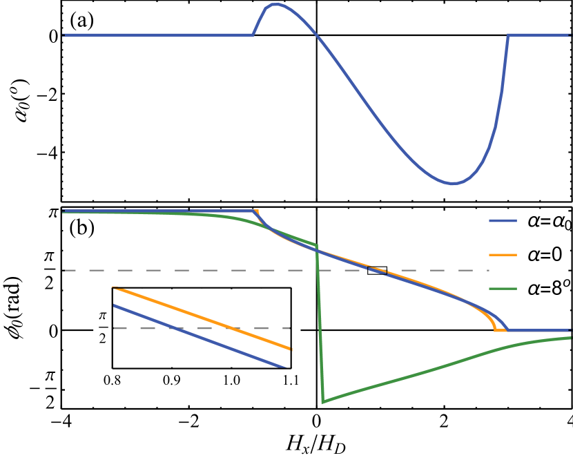
Using Eq. 1, we compute the optimal orientation angle of the undeformed DW and the corresponding internal magnetization IP angle by minimizing . The factor arises because we allow the DW to orient itself with respect to the IP magnetic field at the cost of elongating. For example, a mixed Bloch-Néel DW tilts its normal to better align with the external IP magnetic field. This tilting however would induce a stretching factor of , increasing the energy cost. This effect is illustrated in Fig. 1 (a) and the optimal angle and corresponding minimized angle are shown as a function of in Fig. 2. The energy of the unperturbed DW is then given by .
The profile of shown in Fig. 2 (b) exhibits sharp kinks for both and . This feature arises because in the energy density of Eq. 1 we neglected higher order anisotropy terms proportional to for which are allowed by symmetry. As a consequence, this simplified energy density yields a sharp transition in DW type from mixed Bloch-Néel to pure Néel at as demonstrated in Fig. 2 where saturates to or . To effectively include for the higher order terms in the energy density, we adjust the value of to some fixed value, e.g. as done by Pellegren et al.Pellegren et al. (2017). With this modification, is smooth around or as demonstrated by the green curve in Fig. 2 (b).
To compute the energy of the deformed DW we need to account for a bending energy cost due to exchange interaction. A kink between two DW segments, as illustrated in Fig. 1 (b), gives an energy cost
| (3) |
with and the IP angles of the internal magnetization of the segments. Here, is the distance between neighboring atoms in the magnetic layer. Due to variations in the lattice structure and to account for non-nearest neighbor interactions, an effective value of nm is used. The effect of on the DW dynamics is investigated in the Supplemental Material SM .
The elastic energy is computed by minimizing over and :
| (4) |
The first term is the length of each of the two segments of the deformed DW multiplied by their respective energy densities. The second term is the bending energy for the three corners, see Fig. 1 (b). The third term is the energy of the unperturbed DW.
With this expression we compute , express in terms of and thereby obtain from which the DW velocity is found as . For more detail, see the Supplemental Material SM . In summary, the derivation of the DW velocity involves multiple optimization steps to determine , , , , and finally . Due to the complexity of the elastic energy, these cannot be made analytically. Approximating the elasticity to be proportional to does allow for analytic solutions, but these are not able to fully explain recent experimental observations. For example, Je et al. approximated Eq. 4 by setting , and neglecting the in the first two terms Je et al. (2013). Because Pellegren et al. have chosen a different DW profile, we cannot directly compare the expression in Eq. 1 with their results Pellegren et al. (2017). They do, however, treat as a free parameter and do not find it by optimization. Moreover, they do not account for the bending costs that we model by the terms involving and in Eq. 1. The results discussed in the next section are obtained numerically without making further approximations.
Results. — In Fig. 3(a) the modeled DW velocity as a function of the applied IP magnetic field is shown for different values of (a). Fig. 3(b) shows the asymmetric component for . The kinks in the solid lines at mark the saturation of internal DW magnetization angle into a Néel wall perpendicular to the IP magnetic field. These are expected from the form of Eq. 1 where we neglected terms . The dashed curves are the result of setting fixed to compensate for the simplified energy density.
In the high IP magnetic field regime, i.e. , the profile straightens out. In this regime the azimuthal angle of the internal magnetization is saturated to align with the IP magnetic field, yielding a Néel DW. Due to this saturation, the orientation dependence of the elasticity no longer varies with further increasing . As a result, the elasticity becomes isotropic and the logarithmic increase in velocity is linear with solely due to the gained Zeeman energy.
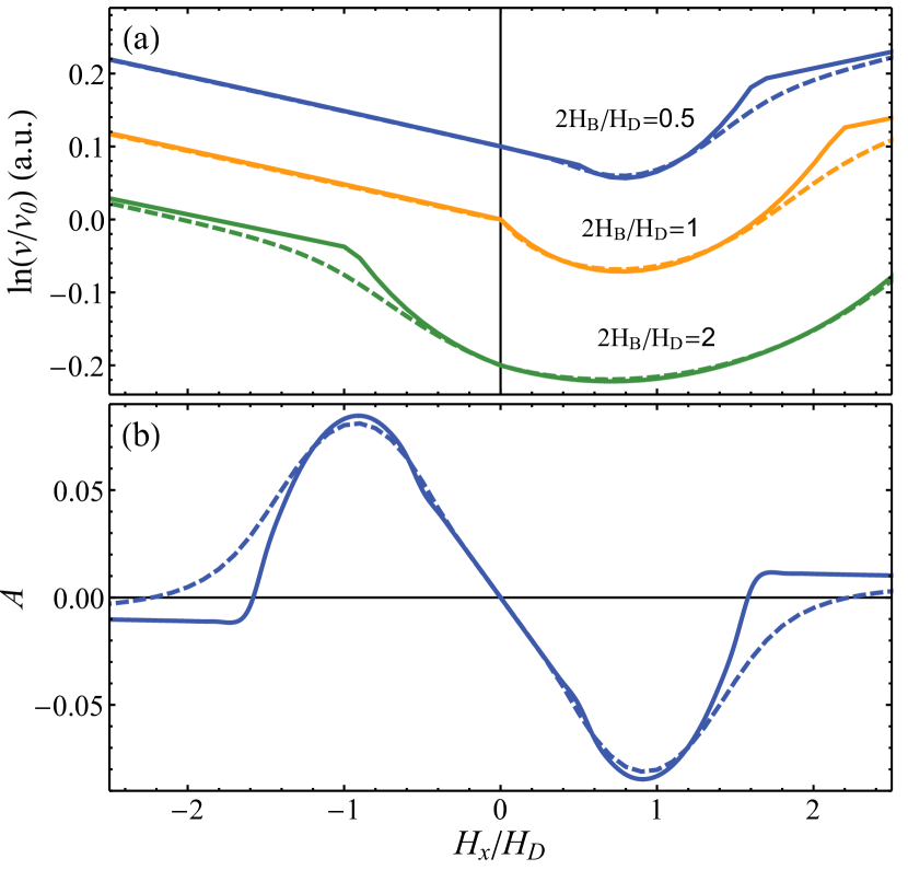
For the DW is mixed Bloch-Néel and the DW velocity provides a distinguishing feature regarding where the steepest slope of the velocity profile with respect to and is found: When the steepest slope is attained at , then (that is, at the DW is purely Néel). Otherwise, there is a steep slope around (where the DW now is mixed Bloch-Néel). This distinction thus indicates the strength of demagnetization relative to DMI.
Note that the demonstrated asymmetry of the profile compares well with experiments Lavrijsen et al. (2015); Hrabec et al. (2014); Jué et al. (2016); Kim et al. (2017, 2018); Pellegren et al. (2017); Lau et al. (2018). Furthermore, the minimal velocity is not attained at as in the model of Je et al. Je et al. (2013).
Note moreover that the asymmetric velocity component switches sign as increases. This feature has been observed experimentally and explained by chiral damping Jué et al. (2016); Kim et al. (2017); Lau et al. (2016). In our model there are no chiral damping effects, showing that this feature need not be an indication for chiral damping.
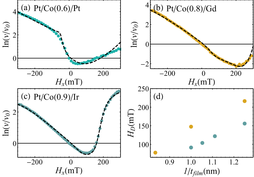
Finally, we compared and fitted our model to experimental data. The results are shown in Fig. 4 showing good quantitative agreement in a broad variety of samples. We performed measurements on two different samples stacks, see Fig. 4 (b) and (c) (see the Supplemental Material for details on these samples, the method of measurement and more fit results SM ). Furthermore, we also interpret data from previous research of Ref. [Lavrijsen et al., 2015] in Fig. 4 (a). In Fig. 4 (d) the obtained values for are plotted as a function of the film thickness and confirm our expectation that should decrease as a function of Metaxas et al. (2007); Thiaville et al. (2012); SM .
| Sample | (a) | (b) | (c) |
|---|---|---|---|
| (T) | |||
| (nm) |
Conclusion. — The DMI and IP magnetic field complexify DW dynamics significantly due to the orientation dependence of elasticity. To grasp and expose this complexity, we defined a model following creep theory and solving the dynamics semi-analytically. The model has a profound sensitivity to DMI and demagnetization. As a result, the model provides a quantitative interpretation of experimental data of DWs that demonstrate asymmetric velocity profiles as a function of .
Experimental studies that do not exhibit a (distinctive) kink at are often fitted with the constant elasticity model proposed by Je et al.Je et al. (2013) In these studies the measurement range of might not be large enough to expose these kinks. Fig. 4(b) demonstrates that our model resembles results from the constant elasticity model of Je et al. Je et al. (2013), but yields a different value of the DMI
The parameter has been set to a fixed value to account for the omission of higher order anisotropy terms in the energy density. As a result the angle will not saturate for large . Previous research used as a fitting parameter as to account for roughness Pellegren et al. (2017). If roughness forces the DW to tilt, the tilting angle is not fixed to one value. Hence a fixed value of should not be interpreted as a physical tilting of the DW.
We remark that assuming to be constant along an axis normal to the DW is only a first approximation. For a Mixed Bloch-Néel DW, will adjust so that the magnetization aligns with the IP magnetic field well inside the domains, but does not at the DW. As plays a key role in the DW dynamics, future research could focus on the exact behavior of .
In recent publications the asymmetric shape of the DW velocity profile as a function of is used as an argument for significant effect of chiral damping on the DW dynamics Jué et al. (2016); Kim et al. (2017); Lau et al. (2018). However, our model demonstrates a similar asymmetry without chiral damping. Furthermore, in the quasi-static creep regime dynamic effects such as chiral damping should not affect creep motion.
The comparison experimental data demonstrates the broad applicability of our model. Future research could apply our model to an extensive sample study to investigate the effects of parameters such as layer thickness or growth.
Acknowledgements.
R.D. is member of the D-ITP consortium, a program of the Dutch Organisation for Scientific Research (NWO) that is funded by the Dutch Ministry of Education, Culture and Science (OCW). This work is funded by the European Research Council (ERC). This work is part of the research programme of the Foundation for Fundamental Research on Matter (FOM), which is part of the Netherlands Organisation for Scientific Research (NWO).References
- Parkin et al. (2008) S. S. Parkin, M. Hayashi, and L. Thomas, Science 320, 190 (2008).
- Moon et al. (2015) K.-W. Moon, D.-H. Kim, S.-C. Yoo, S.-G. Je, B. S. Chun, W. Kim, B.-C. Min, C. Hwang, and S.-B. Choe, Scientific reports 5, 9166 (2015).
- Allwood et al. (2005) D. A. Allwood, G. Xiong, C. Faulkner, D. Atkinson, D. Petit, and R. Cowburn, Science 309, 1688 (2005).
- Hayashi et al. (2008) M. Hayashi, L. Thomas, R. Moriya, C. Rettner, and S. S. Parkin, Science 320, 209 (2008).
- Dzyaloshinskii (1958) I. Dzyaloshinskii, Sov. Phys.—JETP 6, 1130 (1958).
- Moriya (1960) T. Moriya, Phys. Rev. 120, 91 (1960).
- Fert and Levy (1980) A. Fert and P. M. Levy, Phys. Rev. Lett. 44, 1538 (1980).
- Je et al. (2013) S.-G. Je, D.-H. Kim, S.-C. Yoo, B.-C. Min, K.-J. Lee, and S.-B. Choe, Phys. Rev. B 88, 214401 (2013), URL https://link.aps.org/doi/10.1103/PhysRevB.88.214401.
- Boulle et al. (2013) O. Boulle, S. Rohart, L. Buda-Prejbeanu, E. Jué, I. Miron, S. Pizzini, J. Vogel, G. Gaudin, and A. Thiaville, Phys. Rev. Lett. 111, 217203 (2013).
- Lavrijsen et al. (2015) R. Lavrijsen, D. Hartmann, A. Van Den Brink, Y. Yin, B. Barcones, R. Duine, M. Verheijen, H. Swagten, and B. Koopmans, Phys. Rev. B 91, 104414 (2015).
- Jué et al. (2016) E. Jué, C. Safeer, M. Drouard, A. Lopez, P. Balint, L. Buda-Prejbeanu, O. Boulle, S. Auffret, A. Schuhl, A. Manchon, et al., Nature materials 15, 272 (2016).
- Vaňatka et al. (2015) M. Vaňatka, J.-C. Rojas-Sánchez, J. Vogel, M. Bonfim, M. Belmeguenai, Y. Roussigné, A. Stashkevich, A. Thiaville, and S. Pizzini, Journal of Physics: Condensed Matter 27, 326002 (2015).
- Lau et al. (2016) D. Lau, V. Sundar, J.-G. Zhu, and V. Sokalski, Phys. Rev. B 94, 060401 (2016), URL https://link.aps.org/doi/10.1103/PhysRevB.94.060401.
- Pellegren et al. (2017) J. Pellegren, D. Lau, and V. Sokalski, Phys. Rev. Lett. 119, 027203 (2017).
- Kim et al. (2017) D.-Y. Kim, M.-H. Park, Y.-K. Park, J.-S. Kim, Y.-S. Nam, D.-H. Kim, S.-G. Je, B.-C. Min, and S.-B. Choe, Chirality-induced antisymmetry in magnetic domain-wall speed (2017), eprint arXiv:1704.08751.
- Lau et al. (2018) D. Lau, J. P. Pellegren, H. Nembach, J. Shaw, and V. Sokalski, Disentangling factors governing dzyaloshinskii domain wall creep in co/ni thin films using ptxir1-x seedlayers (2018), eprint arXiv:1808.05520.
- Kim et al. (2018) D.-Y. Kim, M.-H. Park, Y.-K. Park, J.-S. Kim, Y.-S. Nam, H.-S. Hwang, D.-H. Kim, S.-G. Je, B.-C. Min, and S.-B. Choe, Phys. Rev. B 97, 134407 (2018).
- Landau and Lifshitz (1955) L. Landau and E. Lifshitz, Phys. Rev. 100, 1243 (1955).
- Li and Zhang (2004) Z. Li and S. Zhang, Phys. Rev. Lett. 92, 207203 (2004).
- Thiaville et al. (2012) A. Thiaville, S. Rohart, Émilie Jué, V. Cros, and A. Fert, EPL (Europhysics Letters) 100, 57002 (2012), URL http://stacks.iop.org/0295-5075/100/i=5/a=57002.
- Lemerle et al. (1998) S. Lemerle, J. Ferré, C. Chappert, V. Mathet, T. Giamarchi, and P. Le Doussal, Phys. Rev. Lett. 80, 849 (1998).
- Kim and Lee (2016) K.-W. Kim and H.-W. Lee, Nature materials 15, 253 (2016).
- Blatter et al. (1994) G. Blatter, M. V. Feigel’man, V. B. Geshkenbein, A. I. Larkin, and V. M. Vinokur, Rev. Mod. Phys. 66, 1125 (1994), URL https://link.aps.org/doi/10.1103/RevModPhys.66.1125.
- Arrhenius (1889a) S. Arrhenius, Zeitschrift für physikalische Chemie 4, 226 (1889a).
- Arrhenius (1889b) S. Arrhenius, Zeitschrift für physikalische Chemie 4, 96 (1889b).
- Kardar and Nelson (1985) M. Kardar and D. R. Nelson, Phys. Rev. Lett. 55, 1157 (1985).
- Fisher and Huse (1991) D. S. Fisher and D. A. Huse, Phys. Rev. B 43, 10728 (1991).
- (28) See Supplemental Material at [URL will be inserted by publisher] for detailed derivations, used standard parameter values and an elaboration on creep theory and the experimental method.
- Hrabec et al. (2014) A. Hrabec, N. Porter, A. Wells, M. Benitez, G. Burnell, S. McVitie, D. McGrouther, T. Moore, and C. Marrows, Phys. Rev. B 90, 020402 (2014).
- Metaxas et al. (2007) P. Metaxas, J. Jamet, A. Mougin, M. Cormier, J. Ferré, V. Baltz, B. Rodmacq, B. Dieny, and R. Stamps, Phys. Rev. Lett. 99, 217208 (2007).