Optimization of neutron diffraction from phase-gratings
Abstract
The recent development of phase-grating moiré neutron interferometry promises a wide range of impactful experiments from dark-field imaging of material microstructure to precise measurements of fundamental constants. However, the contrast of 3 % obtained using this moiré interferometer was well below the theoretical prediction of 30 % using ideal gratings. It is suspected that non-ideal aspects of the phase-gratings was a leading contributor to this deficiency and that phase-gratings needed to be quantitatively assessed and optimized. Here we characterize neutron diffraction from phase-gratings using Bragg diffraction crystals to determine the optimal phase-grating orientations. We show well-defined diffraction peaks and explore perturbations to the diffraction peaks and the effects on interferometer contrast as a function of grating alignment. This technique promises to improve the contrast of the grating interferometers by providing in-situ aides to grating alignment.
I Introduction
Neutrons have played an important role in contemporary physics due to their relatively large mass, electric neutrality, and sub-nanometer-sized wavelengths. Numerous neutron techniques have been developed for the precise measurements of material properties and fundamental constants Sears (1989). In particular, the perfect-crystal neutron interferometer (NI) Rauch and Werner (2015) has made numerous impacts in exploring the properties of the neutron and its interactions Clark et al. (2015); Li et al. (2016); Pushin et al. (2009); Sarenac et al. (2016); Klepp et al. (2014); Denkmayr et al. (2014). Nonetheless, the wide spread adoption of this technique was hindered by its narrow wavelength acceptance and the stringent requirements for environmental isolation, beam collimation, and setup alignment Bauspiess et al. (1978); Arif et al. (1993); Zawisky et al. (2010); Saggu et al. (2016).
A less demanding setup is a grating-based, Mach-Zehnder interferometer which relies on the coherent control and mixing of the various grating diffraction orders Ioffe et al. (1985); Gruber et al. (1989); van der Zouw et al. (2000); Schellhorn et al. (1997); Klepp et al. (2011). However, these interferometers require using cold () or very cold neutrons () with a high degree of collimation; greatly limiting their wide spread use. Some of these limitations are overcome by Talbot-Lau grating interferometers which work in the full-field of a cold neutron beam, with relaxed requirements for wavelength acceptance Clauser and Li (1994); Pfeiffer et al. (2006); Lee et al. (2009). Talbot-Lau grating interferometers have a peak visibility for the design wavelength and have the negative aspect of needing high aspect ratio neutron transmission gratings, which are a fabrication challenge.
The recent advances in far-field phase-grating moiré interferometry extends phase-grating neutron interferometry to high intensity sources of thermal neutrons, showing promise for impactful long-path-length experiments and providing new methods of characterizing materials by scanning the autocorrelation length over many orders of magnitude Pushin et al. (2017); Hussey et al. (2016); Sarenac et al. (2018); Brooks et al. (2017, 2018). This novel technique has proven to be advantageous over other neutron interferometry setups in terms of broader wavelength acceptance and less stringent alignment requirements. However, the observed contrast of 3 % Sarenac et al. (2018) needs to be substantially improved.
A major contributor to the observed poor contrast is suspected to be the sub-optimal quality of the high aspect ratio phase-gratings, and a follow up tomography study confirmed that the shape of the phase-gratings that were used was not ideal Heacock et al. (2018). Here we explore direct methods of optimizing the performance of the individual phase-gratings given the non-ideal shapes. Our method measures the diffracted neutron transverse momentum distributions caused by passing through the phase-gratings and determines the optimal orientation for the phase-gratings. The analogous method for optimizing the orientation of phase-gratings for X-rays is deemed crucial for obtaining high interferometer contrast Miao et al. (2016). We therefore expect that our technique will find fruitful applications in optimizing neutron grating interferometers.
II Phase-Grating Diffraction
Neutron optics rely on refraction and diffraction phenomena for beam control and manipulation Klein and Werner (1983). Various shapes of materials with unique neutron indices of refraction can be constructed to induce phase shifts, diffraction, beam displacements, and spin-dependent interactions. The action of such components may intuitively be understood from the fact that inducing a spatially-dependent phase over the neutron wavefunction modifies its momentum distribution.
Consider an incoming neutron wavepacket which is propagating along the -direction and transversing through a material which has a thickness variation along the -direction. The material induces onto the neutron wavefunction a spatially-dependent phase of , where is the mean neutron wavelength, is the scattering length density, and is the material thickness.
The momentum distribution after the material is given by:
| (1) |
where is the Fourier transform, and is the neutron’s spatial wavefunction before the material.
If a neutron wavepacket passes through a phase-grating of period , then will exhibit diffraction peaks with angular separations of
| (2) |
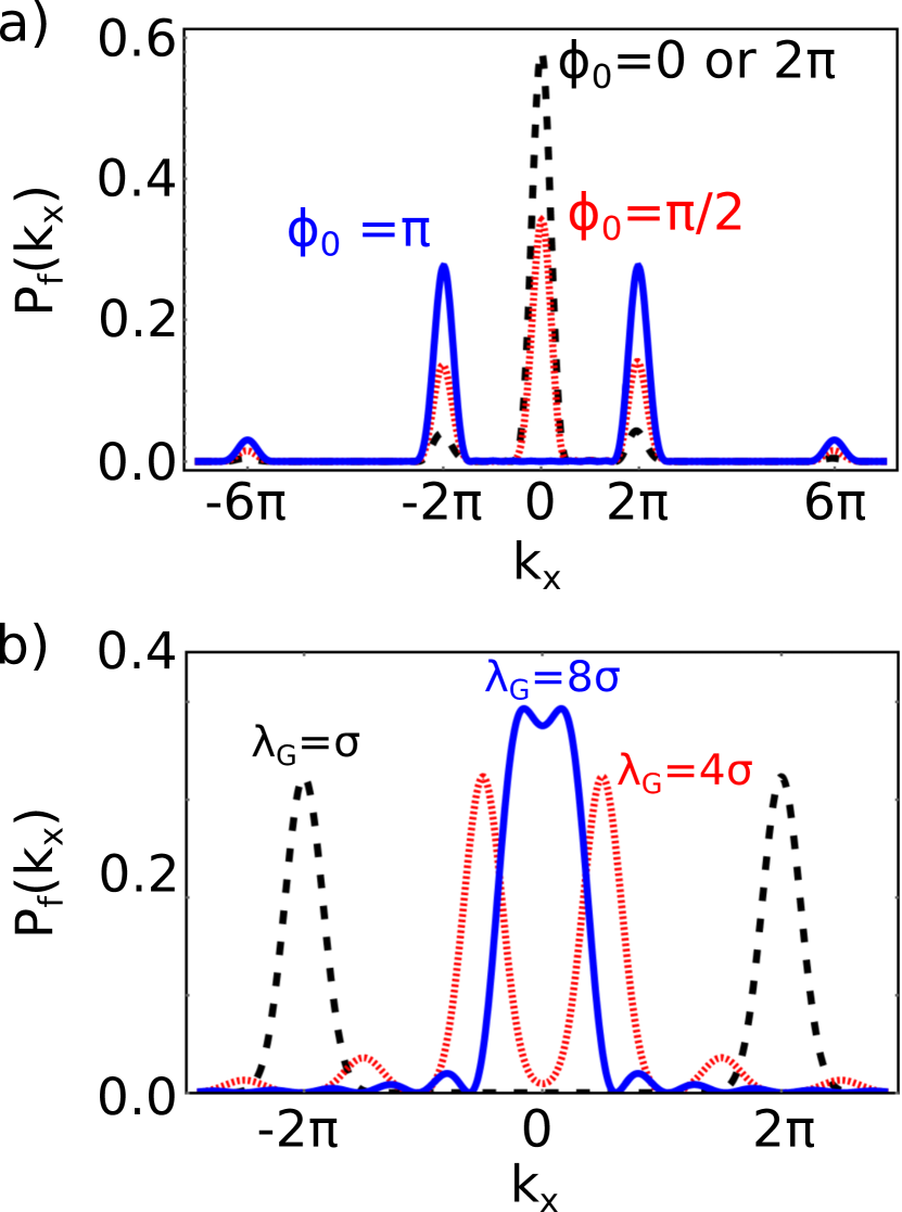
where is an integer that represents the diffraction order. The quality of the diffraction peaks depends on the spatial phase profile induced by the phase-grating. For example, the phase profile of a comb-fraction square wave phase-grating is given by
| (3) |
The corresponding diffracted momentum distribution is shown in Fig. 1a for various amplitudes . Note that for a phase-grating the zeroth diffraction order is suppressed.
To resolve the individual diffraction peaks, the wavepacket’s transverse coherence length must be suitably long compared to the grating period. Fig. 1b shows for a square wave phase-gratings with various periods. It can be seen that as the coherence length of the neutron wavepacket becomes shorter than the period of the grating the diffraction peaks will no longer be well-defined.
III Experimental Methods
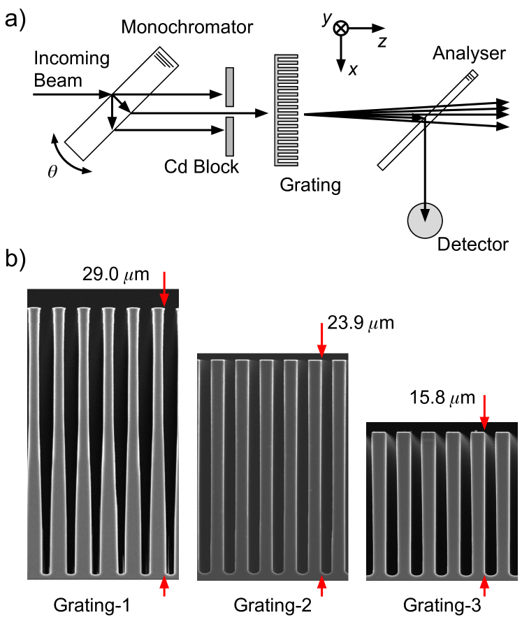
The experiment was performed at the NIOFa beamline at the National Institute of Standards and Technology (NIST) Center for Neutron Research (NCNR) in Gaithersburg, MD Shahi et al. (2016); Pushin et al. (2015). Fig. 2a shows a schematic of the experiment where the neutron momentum distribution is mapped by changing the rotational alignment of the monochromator and analyzer crystal in a double crystal diffractometer (DCD). The apparatus was first introduced in Heacock et al. (2018), where we demonstrated a phase-recovered tomography algorithm. An alternative method of characterizing neutron diffraction from phase-gratings consists of measuring diffraction peaks in the far field using an array of slits, as was done for cold neutrons Eder et al. (1991). In our setup, the smaller slit widths and larger distances between slits that would be required for thermal neutrons are avoided by using a DCD.
The transverse coherence length prepared by the Bragg-diffracted beam in this setup is around Heacock et al. (2018). This is much larger than the grating period of , which is a requirement to be able to resolve the grating-diffracted peaks.
Three Si gratings, all with period m, were analyzed. The depth of Grating-1 was m, Grating-2: m, and Grating-3: m. These thicknesses of Si correspond to a phase shift of 2.6 rad, 2.2 rad, and 1.4 rad, respectively, for neutrons. In Fig. 2b are the profiles of the phase-gratings as shown by the Scanning Electron Microscope (SEM) micrographs.
The gratings were first all analyzed separately. Momentum distributions were measured as a function of rotation about three axes (defined in Fig. 2a): (1) the axis perpendicular to the neutron propagation and grating diffraction directions (axis), (2) the axis defined by the grating diffraction direction (axis), and (3) the propagation beam axis (axis). In addition, momentum distributions were measured with two gratings separated by cm as a function of rotation about the -axis.
IV Rotational Effects on the Resulting Momentum Distribution
-axis rotations
Rotations about the -axis cause the effective grating period to decrease. However, the high aspect ratio of these gratings causes a change in the phase path integral to be the dominant effect. Integrating over the neutron’s trajectory through a phase-grating as a function of rotation about the -axis modifies the effective phase profile from a nominal square wave. We were able to show that this data can be used to reconstruct real-space images of the grating using a phase-recovered tomography algorithm Heacock et al. (2018). In this work we focus on predicting the momentum distribution from the SEM micrographs and analyzing the impact of the grating shape on interferometer performance. Note that this effect is not as pronounced for very cold neutrons Eder et al. (1991), because the phase-gratings used for cold neutrons have aspect ratios close to unity.
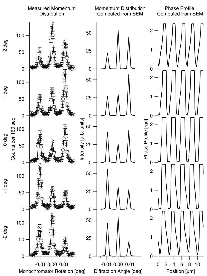
To quantify this effect, the effective phase profiles were computed from the SEM micrographs as a function of rotation about the -axis using silicon’s neutron scattering length density of Å-2 NCN . The momentum distributions were computed by transforming the phase profiles taken from the SEM micrographs according to Eq. 1 using a fast Fourier transform (FFT). The power spectra of the FFT compared to experimental momentum space distributions for Grating-1, along with the effective phase profiles, are shown in Fig. 3.
The diffraction peaks were characterized by fitting the measured intensity versus monochromator rotation to multiple Lorentzians. Fig. 4 compares the areas of the fitted Lorentzians to the areas of the peaks in the FFT power spectra computed from the SEM micrographs. The computed diffraction peak areas from the SEM micrographs were scaled to match the absolute peak areas of the measured distributions, with the relative areas between diffraction orders and grating rotations preserved. The asymmetry in the area under the two first-order diffraction peak areas was unique to Grating-1. This effect can be understood by inspecting the spatial phase profiles computed from the SEM micrographs (see Fig 3). As the grating is rotated, the phase profile has an asymmetrical slope. The sign of the slope changes as the grating rotation crosses zero. This unique phase profile is only seen in Grating-1 because of the trapezoidal grating walls which are visible in the SEM micrograph of Fig. 2b.
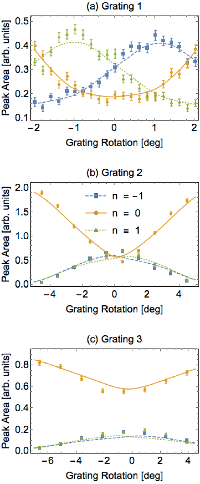
Due to the high aspect ratio of the phase-gratings, the spatially varying phase profile vanishes as the rotation about the -axis approaches degrees. The quality of the grating further diminishes the angular range over which the grating is effective. This can be seen by inspecting the relative peak areas in Fig. 4. Because of the distorted walls of Grating-1, the first order peak areas have a large slope as a function of -axis rotation when the grating is aligned to the beam. This adds a transverse momentum dependence to the diffracted wave amplitudes if the grating is used in a phase-grating NI, which diminishes interferometer contrast. Even for the typical beam divergence of degrees, the angular edges of the beam probe drastically different grating profiles. This effect is absent in Grating-2 and Grating-3, where the diffracted peak areas form a maximum when the grating is aligned to the beam.
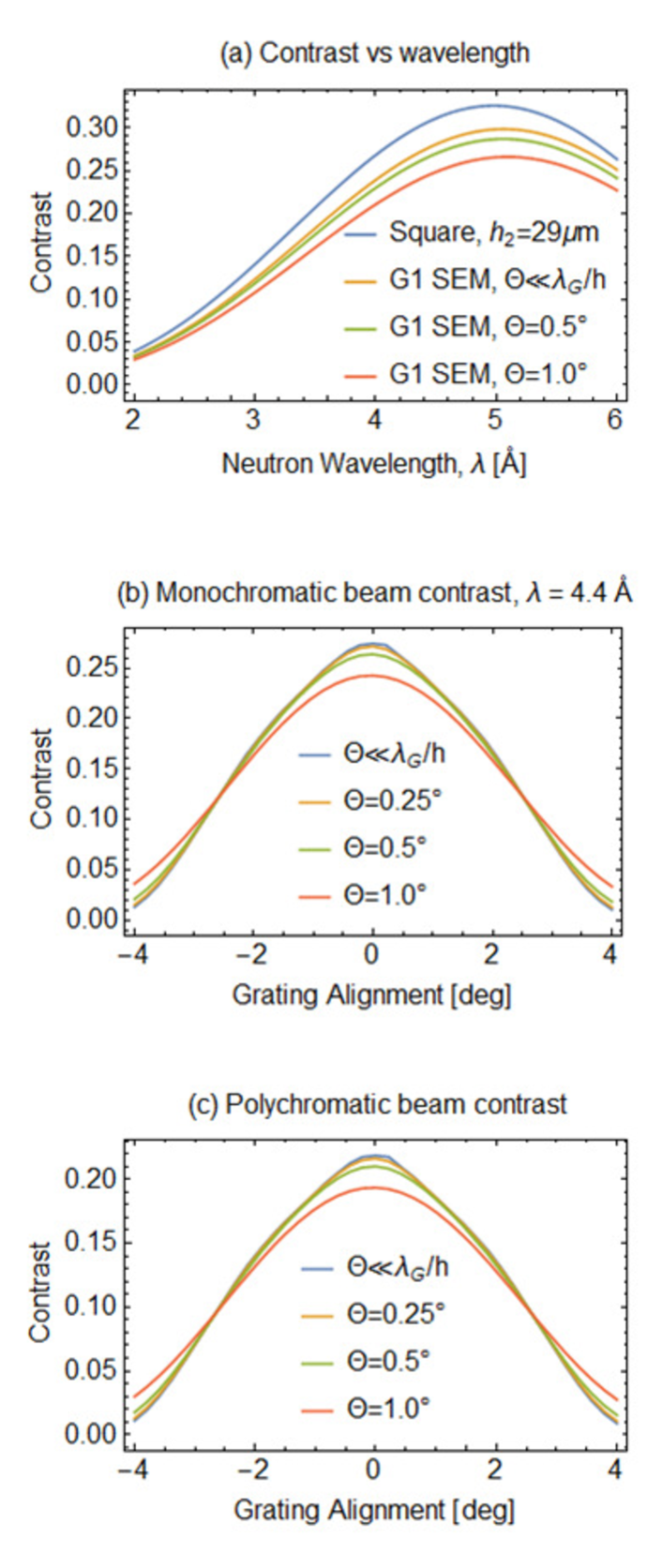
The impact of a non-ideal grating profile on the contrast of a three phase-grating moiré interferometer is is illustrated in Fig. 5. Maximum achievable contrast was calculated by computing the diffracted wave amplitudes from the Grating-1 SEM as previously described. This was combined with the closed-form solution for the diffracted wave amplitudes for square gratings with heights of and 16 m. The three phase-grating moiré pattern maximum contrast was then computed according to the equations set out in Miao et al. (2016), with Grating-1 used as the central grating. Contrast is computed as a function of wavelength and the angular alignment of the central grating about the -axis. The resulting function can then be integrated over a wavelength and/or angular distribution. In our case, we take the angular distribution to be Gaussian with width and assume either a monochromatic or Maxwell-Boltzmann distributed source. A reduction in contrast from the non-square profile of Grating-1 is clearly visible for all wavelengths (Fig. 5a), and beam divergence at the level of most neutron experiments () also reduces contrast. Note that the effect of beam divergence is only considered for the central grating, which would dominate the effect, as it is twice the height of the other two gratings. Finally, computing contrast versus the angular alignment of the central grating for a neutron beam with a wavelength distribution given by a Maxwell-Boltzmann distribution with Å, as was the case in the first demonstration of a neutron three phase-grating moiré interferometer Sarenac et al. (2018), we show that the lower-than-expected contrast could have occurred from a 3.5 degree misalignment of the central grating about the -axis.
-axis Rotations
Rotations about the -axis only change the effective thickness of the grating, and therefore the phase profile of the grating changes as
| (4) |
A comb-fraction grating with a phase amplitude theoretically has the zeroth-order peak suppressed as shown in Fig. 1a. As the amplitude of the zeroth order peak is proportional to , the peak reappears slowly as a function of grating thickness. Demonstration of the zeroth-order peak suppression is shown in Fig. 6 by rotating Grating-2 about the -axis.
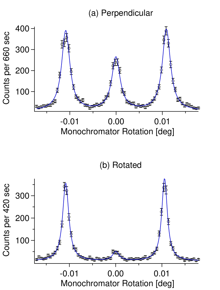
However, the disappearance of the zeroth-order peak does not hold true for a phase-grating with sloped walls. Thus, if a phase-grating is known to be aligned to the -axis, as in the previous section, the lack of a zeroth order peak is a measure of the squareness of the grating. The almost complete suppression of the zeroth order peak seen in Fig. 6b matches the SEM micrograph in Fig. 2 in that Grating-2 is of very high uniformity and its shape closely estimates a square wave.
-axis rotations
Grating rotations about the -axis rotate the diffraction plane of the grating out of the diffraction plane of the monochromator-analyzer pair (the - plane in Fig. 2a). This can be interpreted as effectively lengthening the grating’s period by
| (5) |
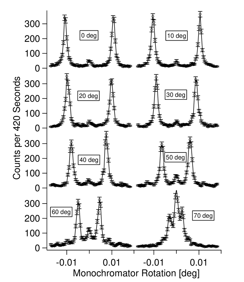
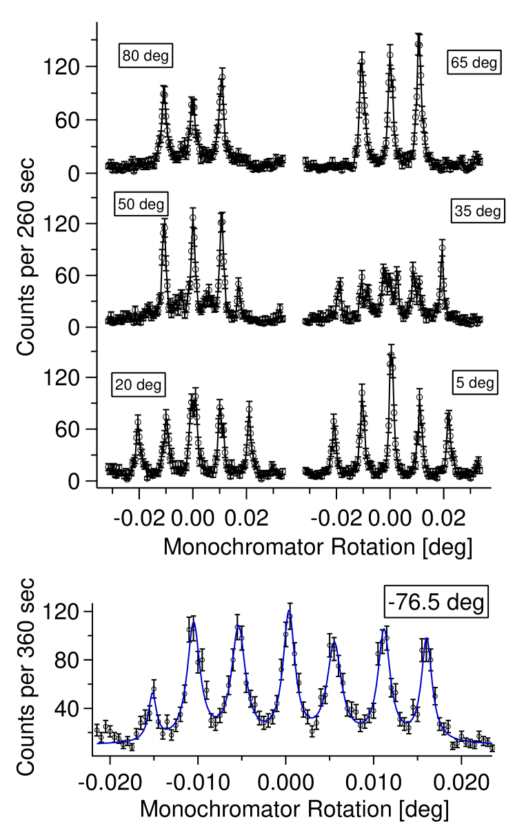
where is the angle of elevation between the crystal and grating diffraction planes about the -axis. Because the momentum distribution is only narrow in the crystal diffraction direction, rotating the grating about the -axis reduces the ratio (see Fig. 1b). This causes the measured diffraction peaks to overlap as the grating is rotated as shown in Fig. 7.
z-axis rotations with two gratings
When two gratings with the same period are used in series, the -order diffraction peaks from the first grating are diffracted into order peaks, where is the diffraction order of the second grating. The measured momentum distribution of Grating-1 and Grating-2 operated in series is shown in Fig. 8. Second order diffraction peaks now have amplitudes similar to the first and zeroth order peaks.
If one or both of the gratings are rotated about the -axis, Eqn. 2 is modified and the crystal monochromator / analyzer pair will measure peak locations of
| (6) |
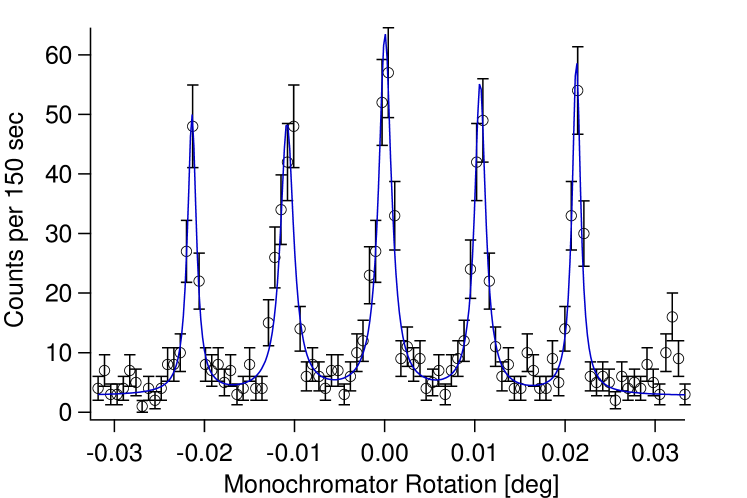
for two gratings of the same period , with and the -axis rotation of Grating-1 and Grating-2, respectively. The effect of rotating one grating about the -axis while leaving the other aligned is shown in Fig. 9. The number of observable peaks increases because need not add to an integer between and for and restricted to . As shown in Fig. 9b seven diffraction peaks were resolvable; though up to nine peaks are possible.
V Conclusion
We have demonstrated a method to determine the grating orientation which produces the optimal grating interferometer contrast. By characterizing the diffraction peaks of a neutron phase-grating with a crystal monochromator-analyzer pair, we show how the grating’s alignment with the beam impacts the resulting momentum distribution. Rotations about each of the three axes for the coordinate system defined by the diffraction plane of the grating resulted in different effects.
Rotations about the axis change the effective phase profile of the grating. This alters the relative diffracted wave amplitudes in a way that can be predicted from the SEM micrographs of the grating. We find that a grating with distorted walls exhibits a gradient in the measured first order diffraction peak areas as a function of rotation about the -axis, which degrades contrast in a phase-grating NI. The overall phase of the grating is set by its depth and the neutron wavelength; rotating the grating about the -axis changes the effective depth of the grating. We used this degree of freedom to tune a grating to have a phase of and almost completely suppress the zeroth order diffraction peak. Rotations about the -axis tilts the diffraction plane of the grating relative to the monochromator-analyzer pair. This allowed us to measure the outgoing momentum distribution as the grating period approached and became larger than the coherence length of the neutron wavepacket.
Measuring the momentum distribution of a neutron beam diffracted by a phase-grating provides a useful grating characterization tool. A crystal monochromator-analyzer pair could be used in-situ for the pre-alignment of grating NIs, where each grating could be aligned to the incoming beam separately. For high contrast in a three phase-grating moiré interferometer, the middle grating needs to act as a good phase-grating Miao et al. (2016). Here we can conclude that the demonstration of the neutron three phase-grating moiré interferometer achieved a low contrast of 3% most likely because it used the trapezoidal-shaped Grating-1, without any rotational optimization, as the middle grating.
VI Acknowledgments
This work was supported by the U.S. Department of Commerce, the NIST Radiation and Physics Division, the Director’s office of NIST, the NIST Center for Neutron Research, the National Institute of Standards and Technology (NIST) Quantum Information Program, the US Department of Energy under Grant No. DE-FG02-97ER41042, and National Science Foundation Grant No. PHY-1307426. This work was also supported by the Canadian Excellence Research Chairs (CERC) program, the Canada First Research Excellence Fund (CFREF), the Natural Sciences and Engineering Research Council of Canada (NSERC) Discovery program, and the Collaborative Research and Training Experience (CREATE) program.
References
- Sears (1989) Varley F Sears, Neutron optics: an introduction to the theory of neutron optical phenomena and their applications, Vol. 3 (Oxford University Press, USA, 1989).
- Rauch and Werner (2015) Helmut Rauch and Samuel A Werner, Neutron Interferometry: Lessons in Experimental Quantum Mechanics, Wave-Particle Duality, and Entanglement, Vol. 12 (Oxford University Press; 2 edition, 2015).
- Clark et al. (2015) Charles W Clark, Roman Barankov, Michael G Huber, Muhammad Arif, David G Cory, and Dmitry A Pushin, “Controlling neutron orbital angular momentum,” Nature 525, 504–506 (2015).
- Li et al. (2016) K Li, M Arif, DG Cory, R Haun, B Heacock, MG Huber, J Nsofini, DA Pushin, P Saggu, D Sarenac, et al., “Neutron limit on the strongly-coupled chameleon field,” Physical Review D 93, 062001 (2016).
- Pushin et al. (2009) Dmitry A Pushin, M Arif, and D. G. Cory, “Decoherence-free neutron interferometry,” Physical Review A 79, 053635 (2009).
- Sarenac et al. (2016) Dusan Sarenac, Michael G Huber, Benjamin Heacock, Muhammad Arif, Charles W Clark, David G Cory, Chandra B Shahi, and Dmitry A Pushin, “Holography with a neutron interferometer,” Optics Express 24, 22528–22535 (2016).
- Klepp et al. (2014) J. Klepp, S. Sponar, and Y. Hasegawa, “Fundamental phenomena of quantum mechanics explored with neutron interferometers,” Progress of Theoretical and Experimental Physics 2014, 82A01–0 (2014).
- Denkmayr et al. (2014) Tobias Denkmayr, Hermann Geppert, Stephan Sponar, Hartmut Lemmel, Alexandre Matzkin, Jeff Tollaksen, and Yuji Hasegawa, “Observation of a quantum Cheshire Cat in a matter-wave interferometer experiment,” Nat. Commun. 5, 1–7 (2014), arXiv:1312.3775 .
- Bauspiess et al. (1978) Wolfgang Bauspiess, Ulrich Bonse, and Helmut Rauch, “The prototype neutron interferometer at the grenoble high flux reactor,” Nuclear Instruments and Methods 157, 495–506 (1978).
- Arif et al. (1993) M Arif, MS Dewey, GL Greene, and WM Snow, “Facilities for fundamental neutron physics research at the nist cold neutron research facility,” Journal of research of the National Institute of Standards and Technology 98, 135 (1993).
- Zawisky et al. (2010) M Zawisky, J Springer, R Farthofer, and U Kuetgens, “A large-area perfect crystal neutron interferometer optimized for coherent beam-deflection experiments: Preparation and performance,” Nuclear Instruments and Methods in Physics Research Section A: Accelerators, Spectrometers, Detectors and Associated Equipment 612, 338–344 (2010).
- Saggu et al. (2016) Parminder Saggu, Taisiya Mineeva, Muhammad Arif, DG Cory, Robert Haun, Ben Heacock, MG Huber, Ke Li, Joachim Nsofini, Dusan Sarenac, et al., “Decoupling of a neutron interferometer from temperature gradients,” Review of Scientific Instruments 87, 123507 (2016).
- Ioffe et al. (1985) A I Ioffe, V S Zabiyakin, and G M Drabkin, “Test of a diffraction grating neutron interferometer,” Phys. Lett. 111, 373–375 (1985).
- Gruber et al. (1989) Manfred Gruber, Kurt Eder, Anton Zeilinger, Roland G’́ahler, and Walter Mampe, “A phase-grating interferometer for very cold neutrons,” Physics Letters A 140, 363 – 367 (1989).
- van der Zouw et al. (2000) G van der Zouw, M. Weber, J. Felber, R. Gähler, P. Geltenbort, and A. Zeilinger, “Aharonov–Bohm and gravity experiments with the very-cold-neutron interferometer,” Nucl. Instruments Methods Phys. Res. Sect. A Accel. Spectrometers, Detect. Assoc. Equip. 440, 568–574 (2000).
- Schellhorn et al. (1997) Uwe Schellhorn, Romano A. Rupp, Stefan Breer, and Roland P. May, “The first neutron interferometer built of holographic gratings,” Phys. B Condens. Matter 234-236, 1068–1070 (1997).
- Klepp et al. (2011) J Klepp, C Pruner, Y Tomita, C Plonka-Spehr, P Geltenbort, S Ivanov, G Manzin, K H Andersen, J Kohlbrecher, M A Ellabban, and M Fally, “Diffraction of slow neutrons by holographic SiO_{2} nanoparticle-polymer composite gratings,” Phys. Rev. A 84, 013621 (2011).
- Clauser and Li (1994) John F. Clauser and Shifang Li, “Talbot-vonLau atom interferometry with cold slow potassium,” Phys. Rev. A 49, R2213–R2216 (1994).
- Pfeiffer et al. (2006) F Pfeiffer, C Grünzweig, O Bunk, G Frei, E Lehmann, and C David, “Neutron Phase Imaging and Tomography,” Physical Review Letters 96, 215505 (2006).
- Lee et al. (2009) Seung Wook Lee, Daniel S Hussey, David L Jacobson, Cheul Muu Sim, and Muhammad Arif, “Development of the grating phase neutron interferometer at a monochromatic beam line,” Nuclear Instruments and Methods in Physics Research Section A: Accelerators, Spectrometers, Detectors and Associated Equipment 605, 16–20 (2009).
- Pushin et al. (2017) DA Pushin, D Sarenac, DS Hussey, H Miao, M Arif, DG Cory, MG Huber, DL Jacobson, JM LaManna, JD Parker, et al., “Far-field interference of a neutron white beam and the applications to noninvasive phase-contrast imaging,” Physical Review A 95, 043637 (2017).
- Hussey et al. (2016) Daniel S Hussey, Houxun Miao, Guangcui Yuan, Dmitry Pushin, Dusan Sarenac, Michael G Huber, David L Jacobson, Jacob M LaManna, and Han Wen, “Demonstration of a white beam far-field neutron interferometer for spatially resolved small angle neutron scattering,” arXiv preprint arXiv:1606.03054 (2016).
- Sarenac et al. (2018) D Sarenac, DA Pushin, MG Huber, DS Hussey, H Miao, M Arif, DG Cory, AD Cronin, B Heacock, DL Jacobson, et al., “Three phase-grating moiré neutron interferometer for large interferometer area applications,” Physical review letters 120, 113201 (2018).
- Brooks et al. (2017) Adam J Brooks, Gerald L Knapp, Jumao Yuan, Caroline G Lowery, Max Pan, Bridget E Cadigan, Shengmin Guo, Daniel S Hussey, and Leslie G Butler, “Neutron imaging of laser melted ss316 test objects with spatially resolved small angle neutron scattering,” Journal of Imaging 3, 58 (2017).
- Brooks et al. (2018) Adam J Brooks, Daniel S Hussey, Hong Yao, Ali Haghshenas, Jumao Yuan, Jacob M LaManna, David L Jacobson, Caroline G Lowery, Nikolay Kardjilov, Shengmin Guo, et al., “Neutron interferometry detection of early crack formation caused by bending fatigue in additively manufactured ss316 dogbones,” Materials & Design 140, 420–430 (2018).
- Heacock et al. (2018) B Heacock, D Sarenac, DG Cory, MG Huber, JPW MacLean, H Miao, H Wen, and DA Pushin, “Sub-micrometer resolution neutron tomography,” arXiv preprint arXiv:1808.07476 (2018).
- Miao et al. (2016) Houxun Miao, Alireza Panna, Andrew A Gomella, Eric E Bennett, Sami Znati, Lei Chen, and Han Wen, “A universal moire effect and application in x-ray phase-contrast imaging,” Nature physics 12, 830 (2016).
- Klein and Werner (1983) AG Klein and SA Werner, “Neutron optics,” Reports on Progress in Physics 46, 259 (1983).
- Shahi et al. (2016) CB Shahi, M Arif, DG Cory, T Mineeva, J Nsofini, D Sarenac, CJ Williams, MG Huber, and DA Pushin, “A new polarized neutron interferometry facility at the ncnr,” Nuclear Instruments and Methods in Physics Research Section A: Accelerators, Spectrometers, Detectors and Associated Equipment 813, 111–122 (2016).
- Pushin et al. (2015) DA Pushin, MG Huber, M Arif, CB Shahi, J Nsofini, CJ Wood, D Sarenac, and DG Cory, “Neutron interferometry at the national institute of standards and technology,” Advances in High Energy Physics 2015 (2015).
- Eder et al. (1991) Kurt Eder, Manfred Gruber, Anton Zeilinger, Roland Gähler, and Walter Mampe, “Diffraction of very cold neutrons at phase gratings,” Physica B: Condensed Matter 172, 329–338 (1991).
- (32) https://www.ncnr.nist.gov/resources/n-lengths/elements/si.html.