Super-resolution imaging within reach
Although several optical techniques have been recently developed in order to overcome the resolution limit in microscopy, the imaging of sub-wavelength features is still a real challenge. In practise, super-resolution techniques remain difficult to build or are photo-toxic for the biological samples. However, microsphere-assisted microscopy has recently made super-resolution imaging accessible to scientists (e.g. optical metrologists, engineers and biologists). This paper presents an easy-to-implement optical setup to perform full-field and contactless super-resolution measurements of nanostructured media or biological elements. For this purpose, a classical microscope was enhanced by introducing a transparent microsphere. We show that this rather simple approach makes it possible to achieve a lateral resolution of 200 nm in air, i.e. the visualization of feature sizes of 100 nm.
Key-words: Super-resolution imaging; Microsphere; Laboratory techniques
Introduction Considerable progress has been made in optical microscopy in order to overcome the resolution limit imposed by the diffraction of light [1]. Several imaging techniques have been proposed in order to visualize beyond the ultimate physical barrier of [2]. Among them, we can list confocal microscopy [3] as well as its enhancements (e.g., 4Pi microscopy [4], stimulated-emission-depletion fluorescence microscopy (STED) [5], and photonic-jet-based scanning microscopy [6]), scanning near-field optical microscopy (SNOM) [7, 8], metamaterial-based superlenses [9, 10], and structured illumination microscopy (SIM) [11, 12]. In addition, the Nobel Prize for Chemistry rewarded advances in optical nanoscopy in 2014 [13]. However, these super-resolution techniques appear to be complex to set up, need the use of fluorescent labels, are photo-toxic for the sample, or require long-acquisition times.
In 2011, a new imaging technique, microsphere-assisted microscopy, was reported [14], experimentally demonstrating the visualization of object features having 50 nm of size in air (in reality, the lateral resolution is 100 nm according to the Abbe criterion [15]). Immersion microsphere-assisted microscopy was suggested shortly after [16]. The physical explanation behind the super-resolution phenomenon is still currently not fully explained. Moreover, the performance of microsphere-assisted microscopy depends on geometrical (e.g., microbead diameter) as well as optical (e.g., wavelength of light or refractive index) parameters. However, the scientific community highlights the probable conversion of the near-field information to propagating waves [17], allowing the lateral resolution to be superior to that attainable by confocal microscopy and by the solid immersion lens [18], and to be similar to that achieved from SIM and superlenses. In addition, the influence of the coherence of light on the imaging performance has been studied [19], as has been the image formation process, by considering the photonic jet as the focal point of the microsphere [20]. Furthermore, microsphere-assisted microscopy has been combined with dark-field imaging for the observation of quasi-transparent samples [21] and with interference microscopy for high-resolution topography reconstruction [22, 23].
This paper features the simple integration of an optical nanoscope using the principle of microsphere-assisted microscopy, i.e. by requiring only a light source, a microscope objective with a microlens, and a camera. The design and the optical assembly for achieving a lateral resolution of 200 nm in air are presented. We show that this simple approach can be used to visualize nanostructured surfaces and intra-cellular elements.
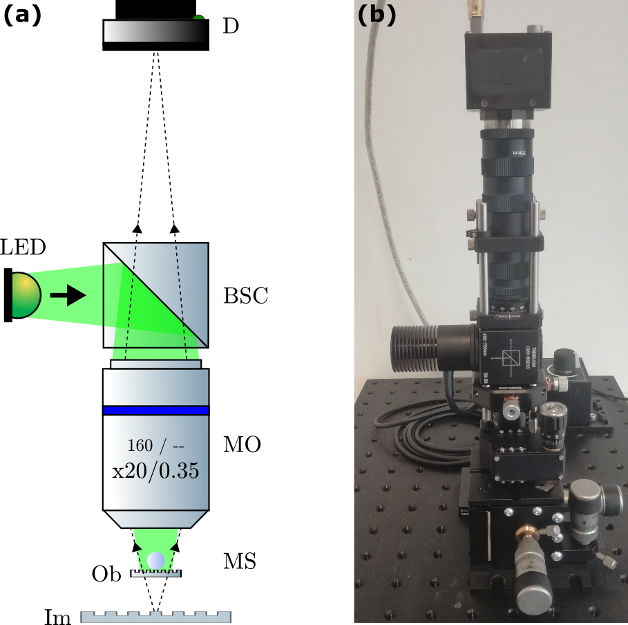
Experimental method The design of the super-resolution optical system slightly differs from an optical microscope only by the introduction of a transparent microsphere. Microsphere-assisted microscopy can thus be seen as an enhancement of white-light microscopy. In this work, the compact nanoscope consists of an illumination part with a light-emitting diode (M530L3, Thorlabs). The wide-field beam is directed by a 50-50 beam-splitter cube onto a microscope objective (20, NA = 0.35, S&H) and then passes through a soda-lime-glass microsphere (SLGMS, Cospheric) in order to illuminate the object. The microsphere is held by a glass plate having a thickness of 150 m and axially positioned using a translation mount (SM1Z, Thorlabs) in order to perform contactless measurements. The microsphere must be at a distance of less than one wavelength from the object. The microsphere can also be placed against the object to perform super-resolution imaging. Finally, the microscope objective collects the virtual image generated by the microsphere and propagates the super-resolution information onto a camera (ec1380, Prosilica). The camera is placed at a distance of 160 mm from the microscope objective (the objective lens is not infinity-corrected, and thus does not require a tube lens to form the image on the camera). A graphical program (LabVIEW, National Instruments) has been developed to record the frames as well as to retrieve the intensity profiles.
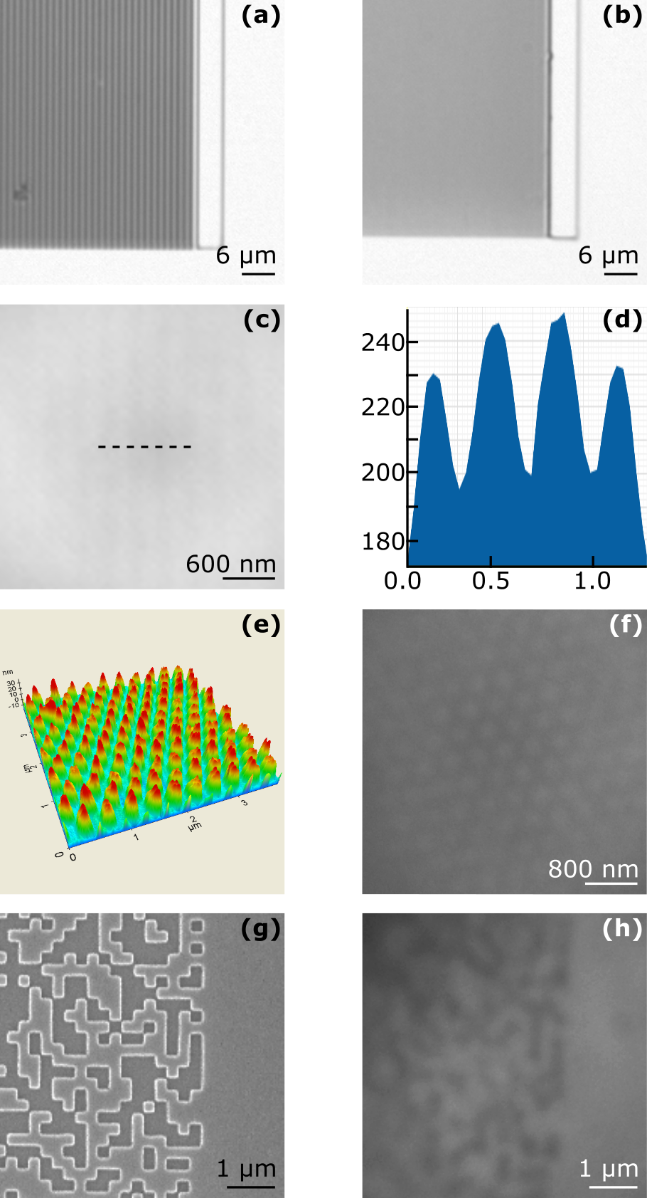
Results Without a microsphere, i.e. using the microscope objective alone, the resolving power of the imaging system equals is 1 m. Figures 2(a) and 2(b) show the ability of the objective lens to record direct images of a standard silicon grating having a period of 1.2 m (features are resolved) and 0.3 m (features are not resolved), respectively. Introducing a 25-m-diameter microsphere between the microscope objective and the standard, at a few hundred nanometers from the surface of the standard, makes it possible to perform super-resolution and thus, to retrieve the 300-nm-period features (Fig. 2(c)) with an imaging contrast of around 10% (Fig. 2(d)), despite the low contrast of the object. Afterwards, the standard grating was replaced by oval-shaped nanodots of Ag covered by a SiON layer (Fig. 2(e)). The periodical nanostructures having a size of 200 nm separated by 200 nm, are resolved by the nanoscope (Fig. 2(f)). A second type of sample was measured, i.e. a matrix of random squares with a side of 250 nm (Fig. 2(g)), in order to validate the super-resolution imaging (Fig. 2(h)).
The use of microsphere-assisted microscopy appears to be very promising not only for contactless nanometrology, but also for cellular (or even intracellular) imaging. Figure 3(a) and 3(b) show the direct images of myelinated brain fibres through the optical microscope alone and through the optical nanoscope, respectively.
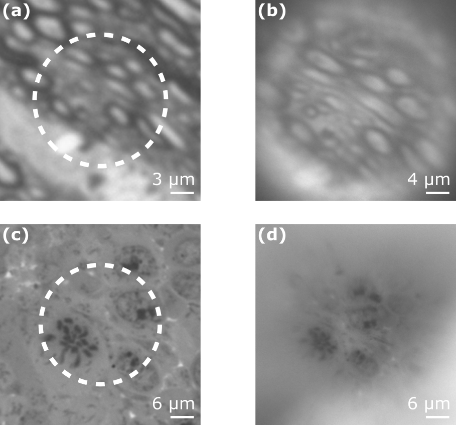
The increase in lateral resolution is remarkable and allows the visualization of cells features with a high accuracy. Figure 3(c) is the direct image of mouse embryo cells through an objective having a higher magnification power (100, NA = 0.9, Leica). This was performed in order to compare the results with those in Fig. 3(d) which represents the image recorded through the 20 objective and a 130-m-diameter microsphere. These two measurements show that a “large” microsphere (e.g., larger than 60 m) provides a similar resolving power as when a high-magnification objective. Nevertheless, the lateral field of view appears to be reduced. A contrast agent (here, uranyl acetate and lead citrate) was required in order to visualize the features of the biological samples (Fig. 3) with a high imaging contrast.
Conclusion This paper aims to help scientists in developing an easy-to-implement optical nanoscope based on microsphere-assisted microscopy. The capacity of this super-resolution imaging technique is demonstrated through the visualization of nanostructures and biological elements. A lateral resolution of 200 nm in air is reached. Furthermore, microsphere-assisted microscopy allows the acquisitions to be full-field, i.e. no lateral scanning is required, and contactless, i.e. not destructive for the samples. Obviously, the resolving power can be improved by performing immersion measurements [A. Darafsheh et al., Appl. Phys. Lett. 101 141128 (2012)] or nanoplasmonic structures [A. Brettin et al., Proc. IEEE NAECON (2017)]. Moreover, a matrix of microspheres can further increase the lateral field of view of the super-resolution system.
Table 1 summarizes the components which were used to build the optical nanoscope (on the date of publication .)
| Items | Reference | Price |
|---|---|---|
| Light source | M530L3, | EUR 255 |
| Thorlabs | ||
| Cube | CCM1-BS013, | EUR 255 |
| Thorlabs | ||
| Objective | S&H, Carl Zeiss | PNA |
| Microsphere | S-SLGMS-2.5, | USD 170 |
| Cospheric | ||
| Camera | ec1380, Prosilica | PNA |
Acknowledgments The authors thank Giorgio Quaranta (CSEM - EPFL, Switzerland) for providing the QR-code-like structures, Thomas Fix (ICube, France) for the Ag nanodots, and the members from the Imaging and Microscopy Platform (IGBMC, France) for the biological samples. Help from the C3-Fab Platform (ICube, France) is also acknowledged. This work has been funded by SATT Conectus Alsace and supported by University of Strasbourg.
References
- [1] S. Perrin and P. Montgomery, ”Fourier optics: basic concepts,” arXiv 1802.07161 [physics.gen-ph] (2018)
- [2] Editorial, ”Beyond the diffraction limit,” Nat. Photonics 3, 361 (2009)
- [3] H. Goldmann, ”Spaltlampenphotographie und - photometrie,” Ophthalmologica 98, 257 (1940)
- [4] S.W. Hell, E.H.K. Stelzer, S. Lindek, and C. Cremer, ”Confocal microscopy with an increased detection aperture: type-B 4Pi confocal microscopy,” Opt. Lett. 19, 222 (1994)
- [5] S.W. Hell and J. Wichmann, ”Breaking the diffraction resolution limit by stimulated emission: stimulated-emission-depletion fluorescence microscopy,” Opt. Lett. 19, 780 (1994)
- [6] Z. Chen, A. Taflove, and V. Backman, ”Photonic nanojet enhancement of backscattering of light by nanoparticles: a potential novel visible-light ultramicroscopy technique,” Opt. Express 12, 1214 (2004)
- [7] E.H. Synge, ”A suggested method for extending microscopic resolution into the ultra-microscopic region,” Phil. Mag. Ser. 7. 6, 356 (1928)
- [8] E.A. Ash and G. Nicholls, ”Super-resolution aperture scanning microscope,” Nature 237, 510 (1972)
- [9] V.G. Veselago, ”The electrodynamics of substances with simultaneously negative values of and ,” Sov. Phys. Usp. 10, 509 (1968)
- [10] J.B. Pendry, ”Negative refraction makes a perfect lens,” Phys. Rev. Lett. 85, 3966 (2000)
- [11] W. Lukosz and M. Marchand, ”Optischen Abbildung Unter Uberschreitung der Beugungsbedingten Auflosungsgrenze,” Opt. Acta 10, 241 (1963)
- [12] B. Bailey, D.L. Farkas, D.L.Taylor, and F. Lanni, ”Enhancement of axial resolution in fluorescence microscopy by standing-wave excitation,” Nature 366, 44 (1993)
- [13] Press release, ”Surpassing the limitations of the light microscope,” NobelPrize.org, 2014 (accessed: October 2018)
- [14] Z. Wang et al., ”Optical virtual imaging at 50 nm lateral resolution with a white-light nanoscope,” Nat. Commun. 2, 218 (2011)
- [15] M. Duocastella et al., ”Combination of scanning probe technology with photonic nanojets,” Sci. Rep. 7, 3474 (2017)
- [16] A. Darafsheh et al., ”Optical super-resolution by high-index liquid-immersed microspheres,” Appl. Phys. Lett. 101, 141128 (2012)
- [17] Y. Ben-Aryeh, ”Increase of resolution by use of microspheres related to complex Snell’s law,” J. Opt. Soc. Am. A 33, 2284 (2016)
- [18] A. Darafsheh et al., ”Advantages of microsphere-assisted super-resolution imaging technique over solid immersion lens and confocal microscopies,” Appl. Phys. Lett. 104, 061117 (2014)
- [19] A.V. Maslov and V.N. Astratov, ”Optical nanoscopy with contact Mie-particles: Resolution analysis,” Appl. Phys. Lett. 110, 261107 (2017)
- [20] S. Lecler, S. Perrin, A. Leong-Hoi, and P. Montgomery, ”Photonic jet lens,” Sci. Rep. (2018)
- [21] S. Perrin et al., ”Transmission microsphere-assisted dark-field microscopy,” Phys. Status Solidi RRL. 1800445 (2018)
- [22] S. Perrin et al., ”Microsphere-assisted phase-shifting profilometry,” Appl. Opt. 56, 7249 (2017)
- [23] F. Wang et al., ”Three-Dimensional Super-Resolution Morphology by Near-Field Assisted White-Light Interferometry,” Sci. Rep. 6, 24703 (2016).