Daniel Sánchez, Weiwei Wan, Kensuke Harada 11institutetext: Osaka University, Japan. 11email: wan@hlab.sys.es.osaka-u.ac.jp
Arm Manipulation Planning of Tethered Tools with the Help of a Tool Balancer
Abstract
Robotic manipulation of tethered tools is widely seen in robotic work cells. They may cause excess strain on the tool’s cable or undesired entanglements with the robot’s arms. This paper presents a manipulation planner with cable orientation constraints for tethered tools suspended by tool balancers. The planner uses orientation constraints to limit the bending of the balancer’s cable while the robot manipulates a tool and places it in a desired pose. The constraints reduce entanglements and decrease the torque induced by the cable on the robot joints. Simulation and real-world experiments show that the constrained planner can successfully plan robot motions for the manipulation of suspended tethered tools preventing the robot from damaging the cable or getting its arms entangled, potentially avoiding accidents. The planner is expected to play promising roles in manufacturing cells.
keywords:
Manipulation planning, Constraints, Wired tools1 Introduction
Manipulation planning involves the computation of robot motions to pick up objects and place them in desired poses and requires important considerations to be successful: The initial and goal poses of the manipulated object must be determined, the different grasping poses available to the robot in order to handle the object must be considered, and the intermediate poses of the robot for achieving the object’s goal pose must be computed and executed. Furthermore, planning constraints are often implemented to guarantee that the manipulation task can be performed correctly by preventing unwanted events or following certain end-effector poses [21, 3]. In industry-based scenarios, a robot usually has to handle tools to execute different tasks. In those cases, the tool’s inherent characteristics such as its weight, its shape and (in the case of wired tools) its cable represent hindrances for tool manipulation. A tool’s cable, in particular, represents a difficult problem for robotic manipulation: the robot might get entangled with the cable, causing damage to the tool or itself or it might bend the cable in excess causing wear and tear or its breakage. Also, the properties of the cable itself, such as its fixed points and its flexibility play a major role in the manipulation process. These burdens make the handling of wired or tethered tools a challenge for most manipulation planners, therefore the inclusion of special constraints to prevent or diminish entanglements and excessive cable bending is of great importance for tethered tool manipulation.
In this paper, we present a solution for manipulation planning of tethered tools suspended by tool balancers. Tool balancers are suspended mechanisms placed in a workstation to help to fix tools. A tool balancer is equipped with a retractable cable that forces the tool’s cable to form a straight line by constantly applying a pulling force. The straight line simplifies the problem of cable deformation. This work presents a set of constraints implemented with tool balancers to keep the robot from twisting the cable more than a given maximum angle threshold. The planning algorithms under the constraints help to eliminate robot motions that cause tethered tools’ cables to bend excessively as well as avoid colliding with the cables before grasping, reducing entanglements and large strain.
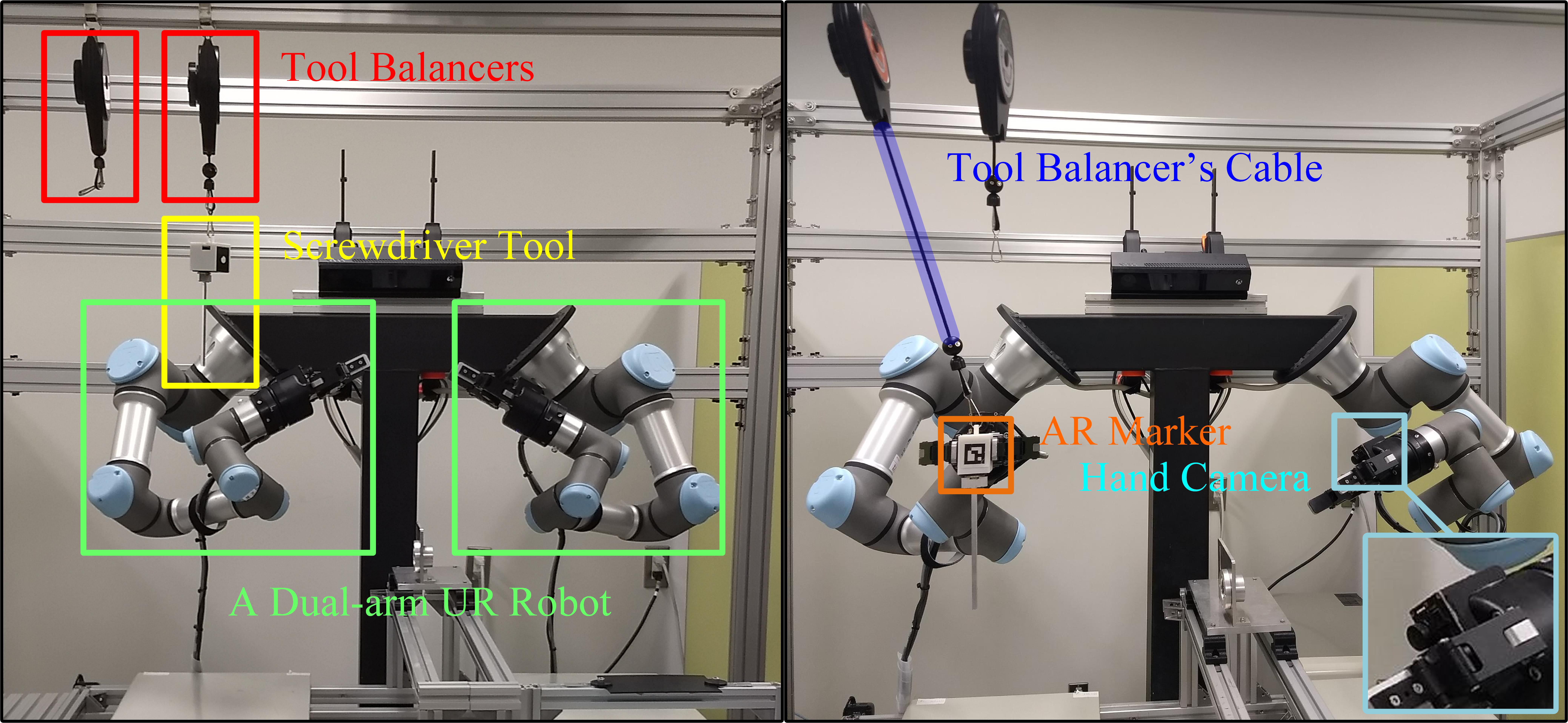
To validate the proposed methods, we performed both simulations and real-world experiments using the setting shown in Fig.1 and a controller developed in our previous work [21, 20]. The results show a significant increase in manipulation success rate and a reduction of the tool’s cable bending as well as the torque borne by the robot arms.
2 Related Work
For decades, manipulation planning has captured the interest of several research projects. Manipulation consists in finding a series of intermediate object poses in order to reach a goal pose. Early work in manipulation solutions for robotic arms [19, 18, 10] explored regrasp planning in fixed single-armed robots. These work presented some guidelines for future research in manipulation planning. Recently, multiple work on manipulation planning has been presented. These work includes the comparison of single-arm and dual-arm algorithms for regrasping [21, 2, 20], a regrasp control policy that uses tactile sensors to plan adjustments for local grasp [6], a planner that computes robot configurations to grasp assembly parts for sequences of collaborative assembly operations [4] and 3D object reorientation using pivoting [7].
In the case of manipulation planning, the consideration of constraints is often used to ensure the correct execution of a manipulation task in restrictive scenarios: In [12], a method of learning multi-step manipulation was presented, it uses demonstration to teach the task as a sequence of key frames and a set of geometric constraints. In [11] a tool used to describe the various motion constraints relative to a manipulation planning problem is proposed. A method for developing locally optimal trajectories for aerial manipulation in constrained environments is presented in [17]. A solution for regrasp planning considering stability constraints in humanoid robots was shown in [16]. These approaches help to illustrate the usefulness of considering environmental or inner constraints in different manipulation scenarios.
On the other hand, robot motion planning involving cable-like objects has presented many challenges, these objects are difficult to manipulate, with often unpredictable deformations and, in the case of cables, they can get entangled around the robot or its surroundings. Several work centered around manipulation planning have tackled different problems associated with deformable objects like cables, chains and hoses [8, 5, 13, 1, 14]. In particular, deformable object manipulation has been explored in different work: In [22] a framework for cable shapes manipulation using a deformation model was shown. A motion planner for manipulating deformable linear objects and tying knots is described in [15] and [9] shows a review on dexterous robotic manipulation of deformable objects by using sensor feedback.
The aforementioned work on manipulation of deformable objects and constraints implementations suggested general solutions for object reorientation under different problematics, but the electric wires of tools are overlooked. It remains difficult to include cable shape prediction, collision, and entanglement avoidance, and motion planning in the same loop. This paper uses a tool balancer to convert the cable constraints into a straight line constraint and implements a planner that addresses the problems caused by wired cables using the constraints. It helps to limit excessive bending of the cable, reduces stress on the robot joints, and help robots to avoid getting entangled with the cable and hitting the tool’s cable before performing a grasp.
3 The Orientation Constraints
The essence of our constraints is the estimation of the angular difference of a cable’s current orientation vector and a tool balancer vector. The cable’s current orientation vector is represented as a vector that points to the tool’s connection point with the cable. The tool balancer vector is represented as a vector that points to a desired cable orientation. The Cartesian angular difference between the two vectors is measured for each robot pose that the planner considers to build the motion path. If the measured angle is above a given threshold, the cable is considered to be excessively bent and the pose/node is discarded, the planner then continues exploring different robot poses until a set of nodes connecting the initial and goal poses of the object is found. The planner also generates a list of obstacles to represent the tool balancer’s cable, and prevents the robot from colliding with the cable before grasping the tool.
Specifically, the planner uses two unitary vectors defined in the world coordinate frame , say and , to calculate the changes in angle between the cable orientation and the tool’s current orientation.
First, our planner evaluates the orientation of a vector in the tool’s reference frame. This vector points to the connection point of the tool to the balancer’s cable disregarding the tool orientation. Second, we use a vector in the world frame to describe the vector that points to the same connection point when the tool is in its initial suspended pose. To transform them to the world frame, we use where is the object’s rotational matrix. In the case of the tool balancer, we made since the balancer is directly above of the tool. Initially the vector that points to the connection point only has a component in the world reference frame.
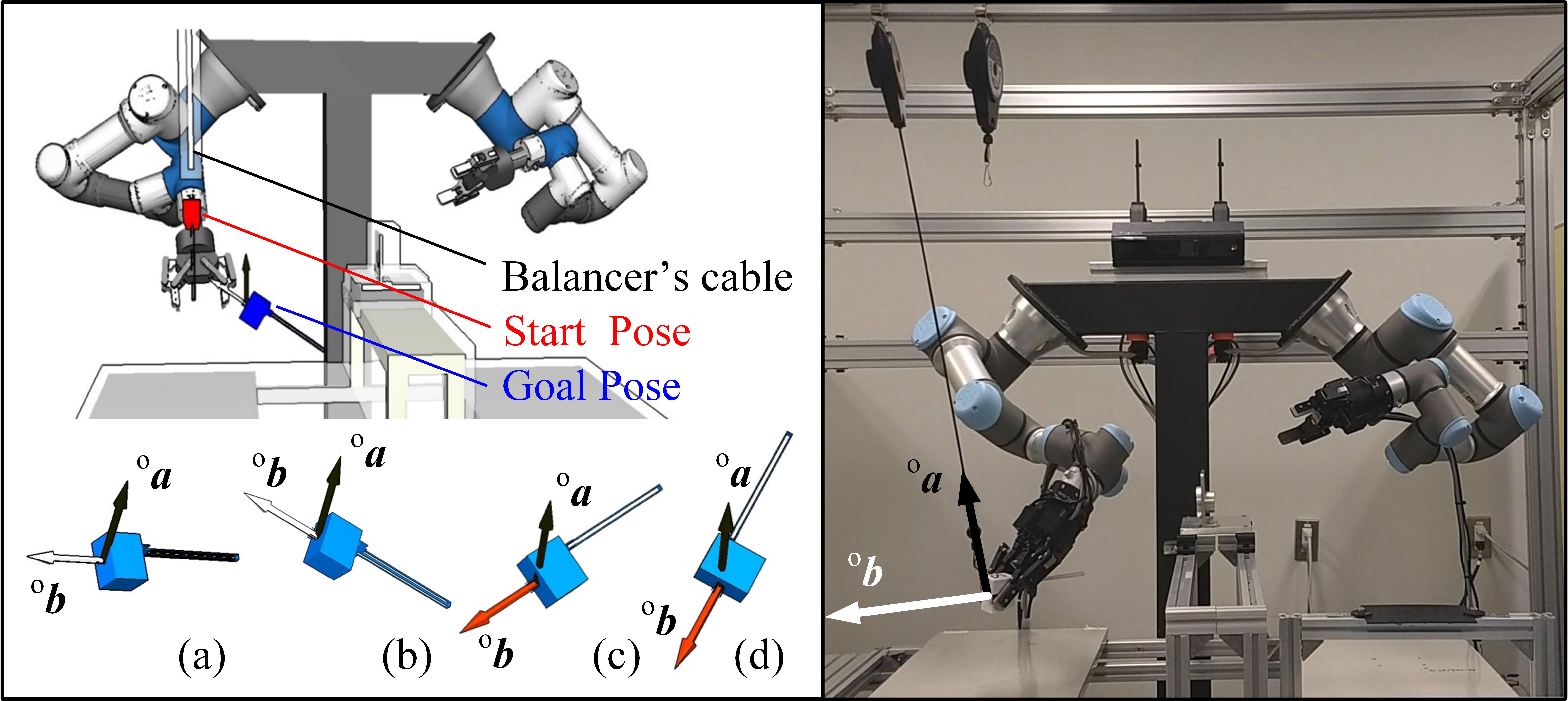
The angular difference between and is computed using = . If is higher than a given threshold the planner considers the cable to be excessively bent, discards the robot pose and continues searching the regrasp graph for other grasps until a path is found. In Fig.2 a demonstration of our simulation environment with different tool orientations is shown to better illustrate vectors and and their angular difference.
We integrated the constraints into a planner published in [21]. First, the planner determines the manipulated tool’s position and orientation by using the robot’s hand camera and the tool’s AR marker, this pose corresponds to the objects starting pose, Second, the object’s goal pose is given to the planner to start the planning process. Third, the cable is represented as an obstacle in the planner: The cable’s shape can be approximated to a straight line, represented by a white cylinder in our simulator as seen in Fig.1. By defining this cylinder as an obstacle, we use collision detection to make the robot avoid the cable before the it grasps the object. Finally, after finding robot poses to grasp the object, the planner continues to build a motion sequence by sampling and connecting a series of compatible grasp poses, the poses must be IK-feasible, collision-free and must assure that the object orientation satisfies the orientation constraints. If the aforementioned is higher than a given threshold, the robot pose violates the constraints and is discarded. In this way, the planner builds a motion sequence for the robot to grasp the object and place it in a desired goal pose while preventing excessive bending of the cable, avoiding possible entanglements and reducing the strain applied on the robot by the retractable cable of the tool balancer.
4 Experiments
To validate the implementation of the aforementioned constraints, we performed both simulation and real-world experiments. For simulations, the tests involved the manipulation of a 3D mesh model of our screwdriver tool. The robot was tasked to pick the tool from a hanging position and place it in a desired goal pose, the experiment was conducted several times with slight variations in the roll and pitch of the starting and goal poses of the tool to test different scenarios. Comparisons were performed with the constrained and unconstrained planner. In the real-world experiments, we used two UR3 arms with mounted cameras in each robot gripper, the cameras were used to capture the original position and rotation of the screwdriver tool with the aid of AR markers. The robot is asked to perform several tasks with distinct goal poses. The robot’s torque sensors and current sensors were used to measure the strain produced by the tool balancer’s cable on the robot.
4.1 Simulations
We performed a series of tests in our simulation environment, shown in Fig.2, to measure and compare the planner’s success rate with different manipulation tasks. We labeled the execution of the tasks using the following criterion: If the tool’s angle difference is higher than a given threshold angle at any point of the task, the execution is labeled as failed by excessive bending of the cable; If the robot hits the balancer’s cable before grasping the object, the execution is identified as a failed case due to collision (In real-world experiments this would modify the tool’s starting pose, making the planned motion ineffective); If the planner is not able to find a path to complete the task, the execution is also labeled as a failure; If the robot is able to perform the task without violating any of the constraints, the execution is labeled as success. Both constrained and unconstrained planners are simulated and labeled following the criterion.
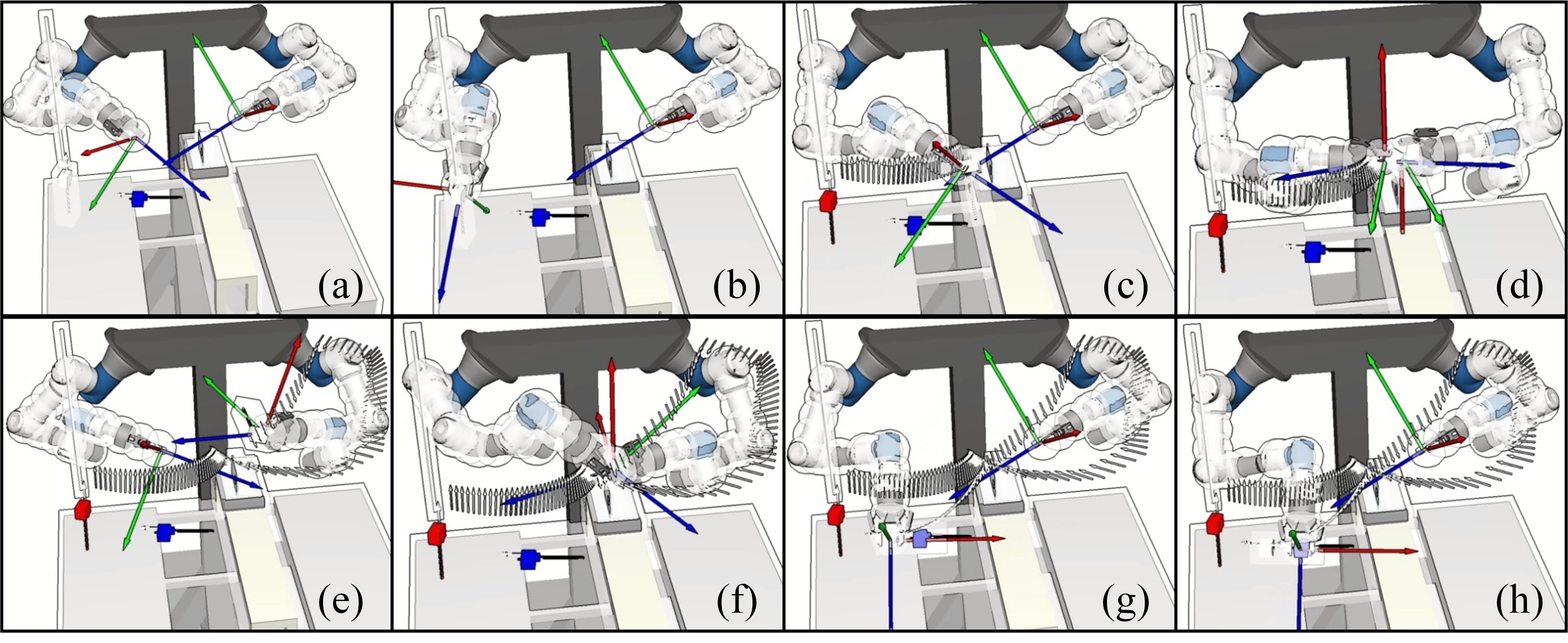
We tasked both constrained and unconstrained planners to find a motion for the robot to grasp the object from a starting pose and move it to a goal pose. We varied the combinations of starting and goal poses by introducing roll and pitch angular rotations (in the tool’s frame of reference ). The results are shown in Table 1. The columns and rows in Table 1 are the varied starting and goal poses combinations. In total, we introduced 5 different goal poses (the columns of Table 1). For each one of these goals, we find the motion for 8 different starting poses (the rows of Table 1). We performed a total of = tests. For the constrained planner, the angle is required to be smaller than 95°at any point in the motion, otherwise the execution will be labeled as a failure. An example of a successful execution considering the constraints is shown in Fig.3.
| Constrained | Unconstrained | ||||||||||||
| -20° | -10° | 0° | 10° | 20° | -20° | -10° | 0° | 10° | 20° | ||||
| 0° | |||||||||||||
| 10° | |||||||||||||
| 15° | |||||||||||||
| 30° | |||||||||||||
| 45° | |||||||||||||
| 60° | |||||||||||||
| 75° | |||||||||||||
| 90° | |||||||||||||
-
Meanings of abbreviations
Results of the constrained and unconstrained planner. The angles in columns and rows show the roll and pitch rotations (in the tool’s frame of reference ) of the starting and goal poses. Symbols: indicates successful planning; indicates that the cable was bent above the threshold angle of 95°; indicates collisions with the balancer’s cable before grasping the object. indicates failure cases where the planner could not find a motion.
The simulation results yielded a 77.5% success rate for the constrained planner. The planner was not able to compute viable solutions for the cases were the roll rotation was of 90°, most likely because the unconstrained solution space for that particular configuration is very limited, making the bending of the cable a requirement to reach the goal pose. In the case of the unconstrained planner, the success rate derived from Table 1 (counting cable collisions, and cable bending as failures) was of 57.5%. In some cases the robot would hit the cable in the simulation (this does not modify the tool’s starting pose in the simulation unlike the real-world) and also bend the cable in order to complete its task, in said cases the results were labeled as failures by bending of the cable.
4.2 Real-world experiments
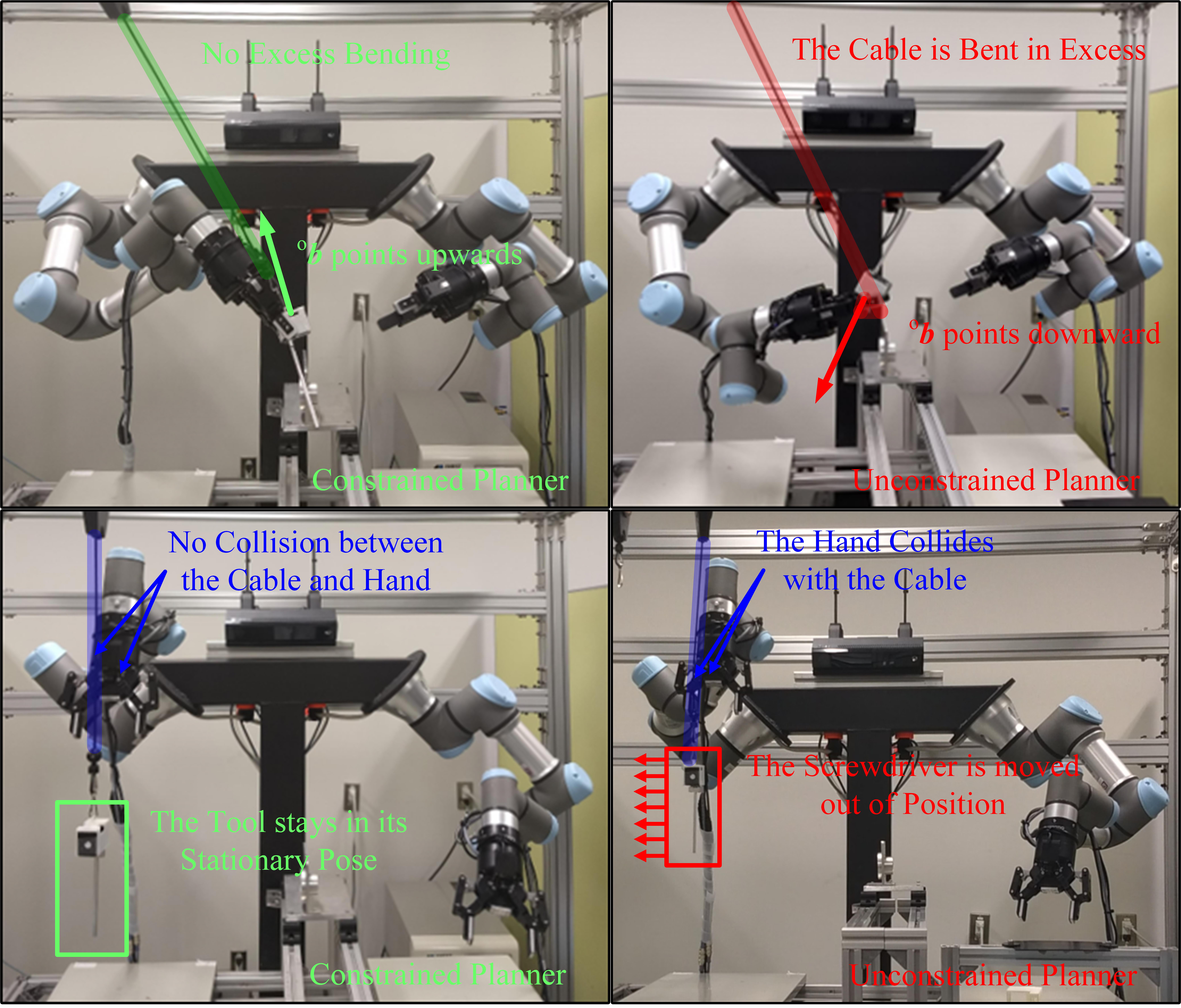
For real-world experiments, we used the dual-arm UR3 robot and a tool balancer to suspend a small screwdriver tool, the robot uses hand-mounted cameras an AR markers to identify the starting pose of the object, as seen in Fig.1. The experiments were performed with and without the constraints presented in this work in order to compare their performances. We tasked the robot to place the tool in several goal poses. After performing several experiments we found that the constrained planner successfully avoids the two undesired cases: When the robot bends the cable in excess or when it collides with it. Fig.4 better illustrates both cases and the solutions presented by the unconstrained planner to avoid them. Statistically, real-world experiments with the constraints yielded a 80% success rate for 15 different executions. In the 3 failed cases, the planner was not able to find a solution. On the other hand, the success rate of the unconstrained planner for the same 15 executions was 46.6%. 5 of the failure cases were caused by collisions with the cable before grasping the tool. The other 4 failure cases were caused by excessive cable bending. A video comparing the constrained and unconstrained executions is available at: http://y2u.be/uTIeeQMYwJ4.
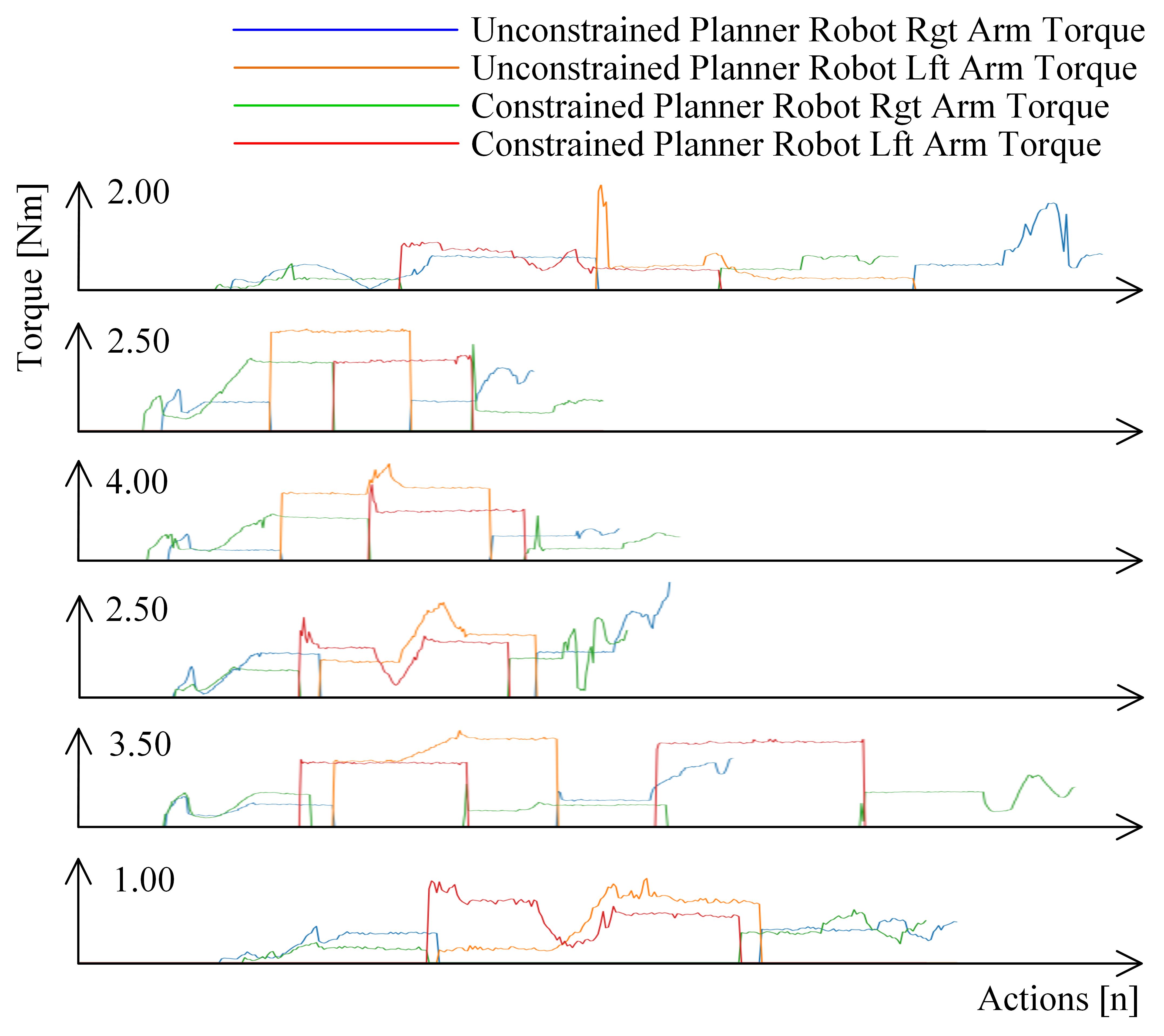
On the other hand, we used torque sensors to measure the changes of strain on the robot’s joints. Fig. 5 shows the magnitude values. The torque magnitudes were recorded every time one of the arms grasps the object, the strong spikes in the measurement occurred when the robot performed handover operations between its grippers. The results show that our constraints reduce the magnitude of the torque suffered by the robot. On average the constrained planner reduced the maximum torque of the two arms by 26.1 % and 20.5 % respectively, diminishing the strain on the robot and the balancer’s cable.
5 Conclusions
A constrained planner for suspended tethered tool manipulation was presented. The planner is examined by both simulation and real-world experiments. Results confirmed that the planner can successfully compute motion sequences for robots to handle balancer-suspended tools, preventing collisions with s tool’s cable and its excess bending, reducing the strain suffered by the robot by diminishing the torque applied by the balancer’s retractable cable on its joints. The planner is expected to play promising roles in manufacturing cells.
References
- [1] Bretl, T., McCarthy, Z.: Quasi-static manipulation of a kirchhoff elastic rod based on a geometric analysis of equilibrium configurations. The International Journal of Robotics Research 33(1), 48–68 (2014)
- [2] Calandra, R., Owens, A., Jayaraman, D., Lin, J., Yuan, W., Malik, J., Adelson, E.H., Levine, S.: More than a feeling: Learning to grasp and regrasp using vision and touch. arXiv preprint arXiv:1805.11085 (2018)
- [3] Cheng, X.: On-line collision-free path planning for service and assembly tasks by a two-arm robot. In: Robotics and Automation, 1995. Proceedings., 1995 IEEE International Conference on, vol. 2, pp. 1523–1528. IEEE (1995)
- [4] Dogar, M., Spielberg, A., Baker, S., Rus, D.: Multi-robot grasp planning for sequential assembly operations. In: Robotics and Automation (ICRA), 2015 IEEE International Conference on, pp. 193–200. IEEE (2015)
- [5] Hert, S., Lumelsky, V.: The ties that bind: Motion planning for multiple tethered robots. Robotics and autonomous systems 17(3), 187–215 (1996)
- [6] Hogan, F.R., Bauza, M., Canal, O., Donlon, E., Rodriguez, A.: Tactile regrasp: Grasp adjustments via simulated tactile transformations. arXiv preprint arXiv:1803.01940 (2018)
- [7] Hou, Y., Jia, Z., Mason, M.T.: Fast planning for 3d any-pose-reorienting using pivoting. In: 2018 IEEE International Conference on Robotics and Automation (ICRA), pp. 1631–1638. IEEE (2018)
- [8] Igarashi, T., Stilman, M.: Homotopic path planning on manifolds for cabled mobile robots. In: Algorithmic Foundations of Robotics IX, pp. 1–18. Springer (2010)
- [9] Khalil, F.F., Payeur, P.: Dexterous robotic manipulation of deformable objects with multi-sensory feedback-a review. In: Robot Manipulators Trends and Development. InTech (2010)
- [10] Lozano-Pérez, T., Jones, J.L., O’Donnell, P.A., Mazer, E.: Handey: a robot task planner (1992)
- [11] Mirabel, J., Lamiraux, F.: Manipulation planning: addressing the crossed foliation issue. In: Robotics and Automation (ICRA), 2017 IEEE International Conference on, pp. 4032–4037. IEEE (2017)
- [12] Pérez-D’Arpino, C., Shah, J.A.: C-learn: Learning geometric constraints from demonstrations for multi-step manipulation in shared autonomy. In: Robotics and Automation (ICRA), 2017 IEEE International Conference on, pp. 4058–4065. IEEE (2017)
- [13] Pham, H., Pham, Q.C.: Robotic manipulation of a rotating chain. IEEE Transactions on Robotics 34(1), 139–150 (2018)
- [14] Ramirez-Alpizar, I.G., Naveau, M., Benazeth, C., Stasse, O., Laumond, J.P., Harada, K., Yoshida, E.: Motion generation for pulling a fire hose by a humanoid robot. In: Humanoid Robots (Humanoids), 2016 IEEE-RAS 16th International Conference on, pp. 1016–1021. IEEE (2016)
- [15] Saha, M., Isto, P.: Motion planning for robotic manipulation of deformable linear objects. In: Robotics and Automation, 2006. ICRA 2006. Proceedings 2006 IEEE International Conference on, pp. 2478–2484. IEEE (2006)
- [16] Sanchez, D., Wan, W., Harada, K., Kanehiro, F.: Regrasp planning considering bipedal stability constraints. arXiv preprint arXiv:1810.06128 (2018)
- [17] Seo, H., Kim, S., Kim, H.J.: Locally optimal trajectory planning for aerial manipulation in constrained environments. In: Intelligent Robots and Systems (IROS), 2017 IEEE/RSJ International Conference on, pp. 1719–1724. IEEE (2017)
- [18] Stoeter, S.A., Voss, S., Papanikolopoulos, N.P., Mosemann, H.: Planning of regrasp operations. In: Robotics and Automation, 1999. Proceedings. 1999 IEEE International Conference on, vol. 1, pp. 245–250. IEEE (1999)
- [19] Tournassoud, P., Lozano-Pérez, T., Mazer, E.: Regrasping. In: Robotics and Automation. Proceedings. 1987 IEEE International Conference on, vol. 4, pp. 1924–1928. IEEE (1987)
- [20] Wan, W., Harada, K.: Reorientating objects with a gripping hand and a table surface. In: Humanoid Robots (Humanoids), 2015 IEEE-RAS 15th International Conference on, pp. 101–106. IEEE (2015)
- [21] Wan, W., Harada, K.: Developing and comparing single-arm and dual-arm regrasp. IEEE Robotics and Automation Letters 1(1), 243–250 (2016)
- [22] Zhu, J., Navarro, B., Fraisse, P., Crosnier, A., Cherubini, A.: Dual-arm robotic manipulation of flexible cables. In: IROS: International Conference on Intelligent Robots and Systems (2018)