A DFT study on the electronic and magnetic properties of triangular graphene antidot lattices
Abstract
We explore the effect of antidot size on electronic and magnetic properties of graphene antidot lattices from first-principles calculations. The spin-polarized density of states, band gap, formation energy and the total magnetization of two different equilateral triangular and right triangular antidots with zigzag and mixed zigzag-armchair edges are studied. We find that although the values of band gap, formation energy and the total magnetization of both structures are different, these values may increase when the number of zigzag edges is increased. The armchair edges have no contribution in the total magnetization of right triangular antidots. The induced magnetic moments are mainly localized on the edge atoms with a maximum value at the center of each side of the triangles. We show that a spin-dependent band gap opens up in bilayer graphene as a result of antidot pattern in only one layer of the structure. Such periodic arrays of triangular antidots that cause a spin-dependent band gap around the Fermi energy can be utilized for turning graphene from a diamagnetic semimetal into a magnetic semiconductor.
I Introduction
Graphene, a single-layer hexagonal lattice of carbon atoms, has been intensively studied in the past decade due to its remarkable electronic, optical, mechanical and thermal properties Novoselov1 ; Geim1 ; Lee1 ; Neto1 . Despite the intrinsically positive features of graphene, its gapless band structure and the lack of intrinsic magnetic property are still a crucial obstacle in the use of this material as an alternative to silicon in nanoelectronics. This suggests that turning the semimetallic graphene into a gapped semiconductor promotes graphene as a key material in many electronic devices. For instance, band gap opening in graphene can be used to fabricate transistors with sufficient on-off ratio Liao ; Wu1 .
To introduce a band gap in graphene, several techniques have been proposed, including adsorption of suitable elements Yavari ; Balog , strain Guinea , substrate-induced symmetry breaking Zhou , synthesis of graphene nanoribbons Han ; Li , and biased bilayer graphene Zhang ; Castro . Moreover, recent studies have shown that a periodic array of holes (antidots) in graphene is another way to open a band gap or to demonstrate wave guiding effects in single-layer graphene Furst ; Vanevic ; Peder ; Ouyang ; Peter ; Pedersen1 ; Power . The electronic and magnetic properties of such graphene antidot lattices (GALs) are strongly dependent on the geometry and edge orientation. Magnetic edge states induced by creating periodic arrays of specific antidots in graphene make these magnetic antidot lattices ideal for spintronic applications. In this context, a recent experiment Schneider has shown that antidot lattices and their potential for programmability can be used in magnonic devices.
Furst et al. Furst studied the electronic band structure of a hexagonal lattice with circular holes by means of Dirac equation, tight-binding calculations and density functional theory (DFT). It was shown that hydrogen passivation along the edges of the holes in DFT calculations has a significant influence on the band structure. Using tight-binding calculations for triangular antidot arrays, it was reported that edge carbon atoms with dangling bonds, have higher on-site potentials, even in the case of hydrogen passivation Vanevic . This feature influences the band structure by shifting and splitting the flat bands around the Fermi energy Vanevic . Pedersen et al. Peder have investigated the hexagonal antidot arrays within the Hubbard model and found that the energy gap is a factor of where is the number of removed atoms for creating an antidot, and is the total number of atoms in the corresponding supercell before antidot formation. The antidot lattices with hexagonal arrays and zigzag edges have also been studied in tight-binding methods and DFT calculations by focusing on bandgap opening/closing OuyangPCCP and considering the effects of inter-antidot distance and the size of antidots on electronic band structure Ouyang .
The previous theoretical works on GALs have mainly focused on hexagonal and circular holes with particular sizes. Although theoretical studies on GALs with triangular holes have also been reported Vanevic ; Liu2009 , these studies which are limited to equilateral triangular antidots have only been investigated by single-band tight-binding approximation without considering the antidot size effects on their electronic properties. Moreover, the formation energy and the total magnetic moment of these triangular holes have not yet been reported.
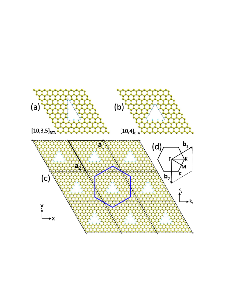
In this paper, we present a study of electronic and magnetic properties of triangular-shape graphene antidots, as periodic hexagonal arrays by means of first-principles calculations. In order to consider the effects of both the armchair and zigzag edges of graphene holes on the band gap opening, two different triangular antidots are examined: Right triangular antidot (RTA) (see Fig. 1(a)) and equilateral triangular antidot (ETA) (see Fig. 1(b)). We find that the values of band gaps, formation energies, and local magnetic moments are strongly dependent on the shape and size of antidots. In addition, we study the influence of antidots on graphene bilayer structures Gregersen2015 ; Kvashnin2015 composed of a single-layer GAL and a pristine graphene layer acting as a substrate for the top GAL. Since the edge states are highly sensitive to the spatial arrangement of the atoms Power ; Farghadan1 and induce magnetic moments on the zigzag-shaped edges in graphene nanoribbons and nanorings Farghadan2 ; Fujita ; Grujic , introducing the ETAs with their pure zigzag edges and also the RTAs with their mixed armchair and zigzag edges in graphene lattices that we consider here, opens up spin-dependent band gaps which may provide a guideline for future magneto-optical experiments in graphene-based nanodevices.
The paper is organized as follows. The methodology and computational details are given in Sec. II. In Sec. III, we present the numerical results of electronic and magnetic properties of graphene RTA and ETA lattices using DFT calculations. Band-gap opening in bilayer graphene with antidot pattern in one of the layers is also discussed. A brief conclusion is given in Sec. IV.
II Computational methods
To investigate the electronic and magnetic properties of triangular GALs, we use two notations, for ETA and for RTA arrays. Here denotes the number of carbon atoms along the supercell edges, represents the number of passivated carbon atoms along the ETA sides, and and are the numbers of passivated carbon atoms along the two perpendicular RTA sides with zigzag and armchair edges, respectively.
The DFT calculations were performed using the SIESTA code sole ; orde , in which the exchange-correlation potential was approximated by the generalized gradient approximation (GGA) pedr . The Perdew-Burke-Ernzerhof (PBE) exchange-correlation functional, norm-conserving Troullier-Martins pseudopotentials, and a double- polarized basis(DZP) are used for this calculation Artacho . All structures are subjected to periodic boundary conditions using a () supercell geometry with basis vectors and in which Å, and vacuum in the direction for pristine graphene structure. Figs. 1(a) and (b) show two supercells with and , respectively. The cut off energy is set to 300 eV and the Brillouin zone sampling is performed by the Monkhorst-pack mesh of k-points. A mesh of (10101) has been adopted for discretization of k-points and a broadening factor of 0.04eV is assumed for the total density of states (TDOS). Moreover, spin-polarized calculations were performed to obtain the total magnetic moment. Also, Mulliken population analysis was used in calculation of local magnetic moment on each carbon atom.
To compare the stability between RTA and ETA lattices with different antidot sizes, the formation energy, , is defined as Zhang1991 ; Reich2005
| (1) |
where is the total energy of the GAL supercell, is the chemical potential of C atom which is taken as the energy of one carbon atom in the perfect graphene, and is the total energy of an isolated molecule. and are the number of carbon and hydrogen atoms in the GAL supercell, respectively.
It is worth mentioning that the formation energy, given in Eq. (1) for GALs, is slightly different with that in the structures with charged defects Zhang1991 . In fact, in the defective structures, depends on the atomic chemical potentials as well as the electron chemical potential Zhang1991 . However, in the GALs consisting of a periodic array of holes (antidots) with the same shapes and sizes, the holes differ from charged defects in graphene. Therefore, although defects can also be deliberately or accidentally introduced into GALs and affect their energy, in this research we focus only on defect-free antidot structures passivated by hydrogen atoms Vanevic ; Furst .
III results and discussion
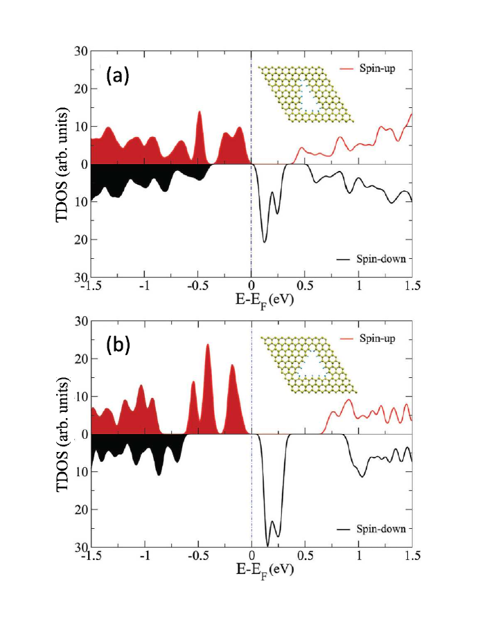
We first investigate how different types of triangular antidots affect the electronic states. Figures 2(a) and (b) show the spin-polarized TDOS in and structures, respectively. Comparing the TDOS in the presence of triangular antidots with that known in pristine graphene clearly shows the band gap opening and the induced midgap states as a result of periodic array of antidots. Due to the zigzag-shaped edges in both structures, localized magnetic moments are induced on the carbon atoms, which make the antidot lattices appropriate for device applications. We see that the density of states is strongly spin dependent with a remarkable difference in their spin density of states around the Fermi energy. The peaks of TDOS in the ETA structure are higher in the midgap region due to more zigzag edges in its supercell. Moreover, the ETA structure shows a larger band gap compared to the RTA structure, indicating that the shape of triangular holes has a strong influence on the size of band gap and the peak of density of states. Interestingly, the Fermi level is located slightly above the occupied states for spin-up electrons, while it is slightly below the midgap-states for spin-down electrons, suggesting a -type (-type) semiconducting behavior for spin-up (spin-down) electrons in both triangular antidot structures. This feature demonstrates that the triangular antidots which exhibit both magnetic and semiconducting properties, can be utilized for spintronic applications.
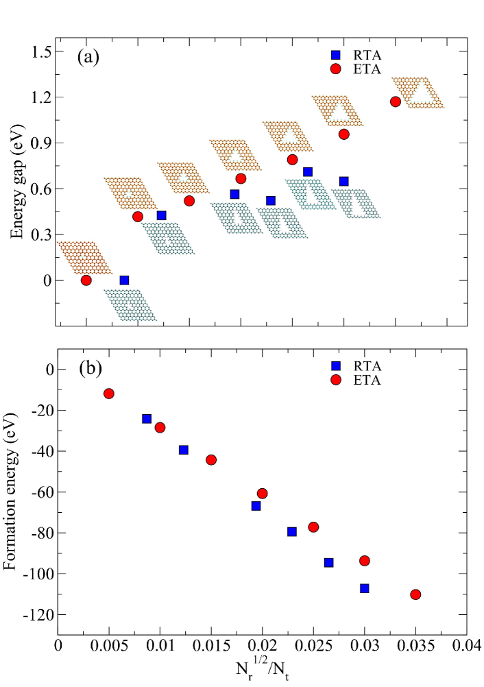
We have also studied the band gap and formation energy of GALs containing triangular antidots with different sizes versus quantity (see Fig. 3). The total number of atoms in each supercell before creating an antidot is =200. As shown in Fig. 3(a), for the first ETA lattice, i.e., [10,1]ETA and also the first RTA lattice, i.e., [10,1,2]RTA the band gaps are zero. For the other structures, however, a gap opens up which roughly increases linearly as both types of structures are increased in size. This increase is more obvious in the case of ETA lattices in which the energy gap can reach 1.17 eV, while it is less than 0.65 eV for the case of RTA lattices which show small deviations from gap increase as a result of single dangling bonds in the triangle side with armchair edges. We see that the value of band gap depends on the size and the shape of antidots. In other words, antidot-antidot interaction which has a profound impact on the band gap is directly related to the antidot density, i.e., the antidot separation. Since this interaction and the overlap between antidots are included in our ab initio calculations, the obtained results can present an accurate description of energy gap values compared to the reported results using tight-binding methods Gunst or Dirac Hamiltonian Peder . The dependence of band gap opening on the size and the shape of antidots suggests the GALs as semiconducting materials with tunable energy gaps.
The total formation energies for different sizes of ETA and RTA antidots are depicted in Fig. 3(b). We see that the formation energy decreases linearly as the number of removed carbon atoms and the added hydrogen atoms is increased. This feature is independent of the antidot shape, indicating that the spatial arrangement of atoms at the edges has a negligible effect on . As the size of antidots is increased, creating a RTA lattice becomes slightly more energetically favorable than creating an ETA lattice, while the energy gaps in ETA structures are slightly larger than those in RTA structures. Interestingly, the linear reduction of formation energy by increasing the size of similar ETA lattices but passivated by oxygen atoms has also been reported in single-layer MoS2 antidots using DFT calculations combined with experiments Gan2016 . Moreover, it is suggested that since the formation energy of all antidot sizes and shapes is negative, it is probably feasible to create them by heating the samples in air Gan2016 . Note that the value and the sign of formation energy of unpassivated defective graphene Thrower ; Haldar , which cause lattice distortion around defects, can significantly change when the edges are terminated by hydrogen atoms. In other words, structural stability of GALs can be achieved by passivating carbon dangling bonds at the edges.
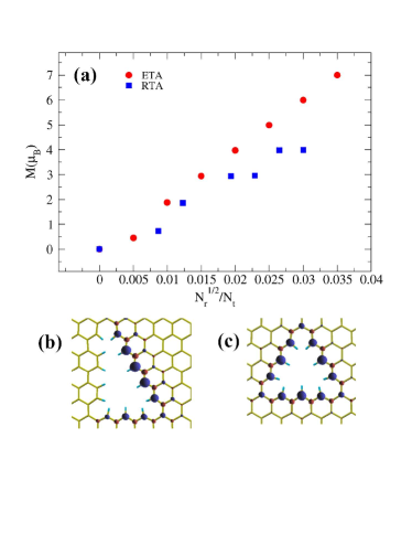
As we mentioned above, the triangular antidots induce magnetic moments at the edges and their neighboring carbon atoms, and hence, the density of states becomes spin dependent. The induced magnetic moments can change with varying the shape and also the size of antidots. In Fig. 4(a), the total magnetic moments, M, are depicted versus ratio for ETA and RTA lattices. Here, represents the magnetic moment of spin-up (spin-down) electrons, localized at site in the supercell. In both structures the total magnetic moment increases with increasing the antidot size. Interestingly, the increase in M is linear in the ETA structures due to the perfect zigzag edges in each side of the triangle, while the RTA structures, which consist of mixed armchair and zigzag edges, exhibit smaller values of magnetic moment compared to those in ETA supercells. Moreover, in most cases the total magnetic moment between two successive values of increases by , due to the saturation of dangling bonds by hydrogen passivation.
We note that in the tight-binding description for a bipartite lattice structure, such as graphene with two sublattices A and B, and only nearest-neighbor coupling, the total magnetic moment per supercell can be determined from Lieb’s theorem Lieb ; Palacios using the relation M=, where is the number of atoms in sublattice A(B) in the supercell. Indeed, the theorem permits to predict the magnetic moment of the ground state by simple counting of the sublattice imbalance. Nevertheless, this theorem does not provide information about the actual local magnetic order or spin texture. For instance, the local magnetic moments may couple antiferromagnetically, while M=0. In contrast, our DFT calculations go beyond the first-neighbor hopping and intersite Coulomb repulsion (Hubbard model) on which the theorem is based.
To compare the distribution of magnetic moments in the two structures, we have shown in Figs. 4(b) and (c) the localized magnetic moments on carbon atoms in [10,3,5]RTA and [10,3]ETA structures, respectively. The blue and red regions represent opposite directions for the moments. Also, the size of each region indicates the magnitude of each moment. As expected, no magnetic moments are formed on the armchair edges, whereas remarkable moments in both structures can be clearly seen on all zigzag edges Saffar-Fargh . The magnetic moments in the same sublattices couple ferromagnetically, while the magnetic moments in different sublattices couple antiferromagnetically. Nevertheless, the total magnetization in such antidots is not zero due to the difference in the total magnetization of A and B sublattices Farghadan3 ; Fern . Moreover, the difference between the distributions of magnetic moments in RTA and ETA is remarkable. We find that the total magnetic moment of RTA lattices does not change, unless the number of armchair edges is increased with increasing the antidot size. On the other hand, the total magnetic moment of ETA lattices always increases as the zigzag edges are increased (see Fig. 4(a)).
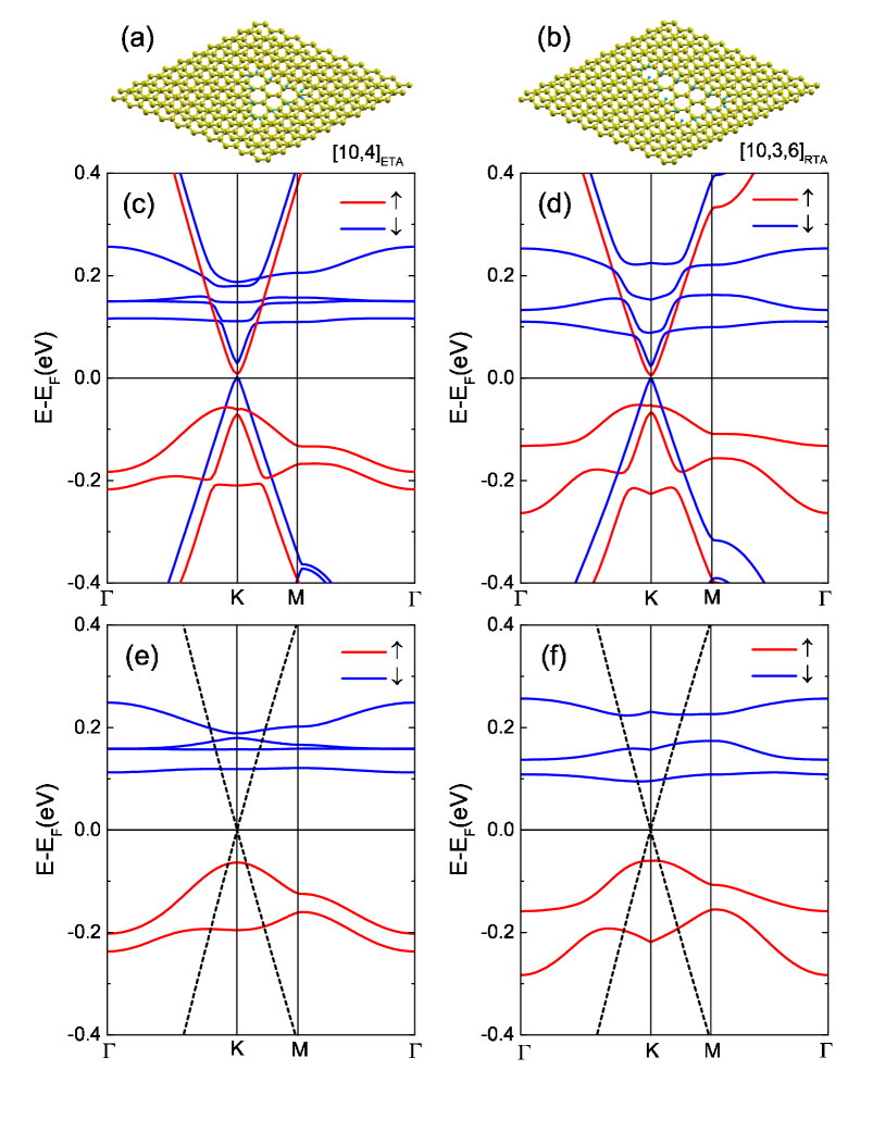
Finally, we consider a bilayer structure consisting of a layer of GAL on top of a pristine graphene layer, arranged in AB stacking. Here, the pristine graphene can act as a substrate for the GAL. Such structures can be realized experimentally, by either standard lithography Oberhuber ; Bai or vdW stacking techniques Geim . The optimized geometries and the band structures of [10,4]ETA and [10,3,6]RTA bilayer GALs are depicted in Figs. 5(a,c), and 5(b,d), respectively . The optimized distance between the top and bottom layers in both ETA and RTA lattices was found to be 3.298 Å, which is very close to the interlayer spacing 3.321 Å in pristine bilayer graphene, computed by our DFT calculations. From Figs. 5(c) and (d), it is evident that the introduction of triangular antidots in the bilayer graphene opens up spin-dependent band gaps, , which are much smaller than those of the single-layer GALs. The band gaps for both spin-up and spin-down electrons are the same in single-layer GALs, while in the bilayer GALs, they are meV and meV in [10,4]ETA lattice and meV and meV in [10,3,6]RTA lattice. The main reason for such smallness in band gaps is due to the creation of antidot pattern in only the top layer of bilayer graphene. Nevertheless, as we have shown in Fig. 3(a) for single-layer GALs, the energy gaps of bilayer GALs are also tunable by changing the antidot size.
To understand the influence of coupling between the top layer with antidots and the bottom layer without antidots on the spin-resolved energy bands of bilayer GALs, we have shown in Figs. 5(e) and 5(f) the distinct energy bands of single-layer GALs and the pristine graphene. We see that in the case of single-layer GALs and within the energy window around the Fermi level, the spin-up (spin-down) energy bands are induced only in the lower (upper) half of the energy window, whereas in the case of bilayer GALs the spin-up and spin-down bands are formed in both sides of the Fermi level as a result of the coupling between single-layer GAL and the pristine graphene in the supercell. By comparing the energy bands of Figs. 5(c,d) with those of Figs. 5(e,f), we find that the interaction between the two layers and also between the magnetic edge states in the top layer can strongly modify the spin subbands and the energy gaps in the bilayer GALs.
Our calculations for the total magnetic moment of bilayer graphene result for the ETA structure, while we obtain for the RTA structure. These values are almost the same as the corresponding values in single-layer GALs (see Fig. 4(a)), suggesting that the interlayer couplings between the two layers in bilayer GALs mostly affect the energy gaps. Furthermore, we see that the Fermi level lies at the minimum of the spin-up conduction band, while it is located at the maximum of the spin-down valence band. In analogy with the single-layer GALs, this behavior reveals that the bilayer GALs can act as -type (-type) semiconductors for spin-up (spin-down) carriers. Moreover, the bilayer GALs can exhibit the band gap values which cannot be produced by single-layer GALs. Therefore, one can selectively tune the energy gap and control the spin of charge carriers either by single-layer GALs or by bilayer GALs.
It is well-known that single-layer graphene has large mobility due to the massless Dirac electrons with linear dispersion Schwierz . On the other hand, it has been demonstrated that the low-energy properties of AB bilayer graphene has two parabolic bands touching each other at the Fermi energy Rozhkov . This feature implies an effective mass for charge carriers and hence a lower mobility which may reduce the device performance of bilayer graphene Schwierz . Therefore, since the gap opening in the single-layer GALs is accompanied by a reduction of charge mobility, the introduction of periodic holes in only one single layer of bilayer graphene can create linear dispersion and enhance the mobility of charge carriers, while the system is still gapped. We note that the result of DFT calculations of a quantum system depends on the type of exchange-correlation functional used. For example, a hybrid functional may overestimate band gaps for semiconductors but underestimate them for insulators Kummel . In contrast, many-body methods based on the use of Green’s functions and perturbation theory as the GW approximation can give more accurate predictions and may change quantitatively the energy gap of GALs. Therefore, a separate numerical investigation of electronic properties of GALs using exchange-correlation potential within the GW approximation is also of practical importance.
IV conclusions
Based on the first-principles simulations we have explored the electronic and magnetic properties of equilateral triangular and right triangular arrays of antidots with different sizes in graphene lattices. We have shown that a spin-dependent band gap is induced in these structures, so that the size of the band gap can be tuned by varying the antidot size and also the inter-antidot separation. The shift of Fermi energy towards valence (conduction) band predicts a -type (-type) semiconducting behavior for spin-polarized electrons in graphene ETA and RTA lattices. The local magnetic moments at armchair edges are zero indicating that these edges do not contribute in the total magnetization of the system. The variation of antidot size in both RTA and ETA lattices shows that the energy gap, formation energy, and the total magnetization increase as the size of antidots is increased.
Moreover, the introduction of an antidot pattern in only one single layer of bilayer graphene opens up a band gap while the energy dispersion remains almost linear around the Fermi energy. Our findings show that the triangular graphene antidot lattices can be utilized as a platform for creating magnetic semiconducting materials with tunable band gaps by varying the size of antidots.
Acknowledgement
We would like to acknowledge supercomputer time provided by the WestGrid and Compute Canada.
References
- (1) K.S. Novoselov, A.K. Geim, S.V. Morozov, D. Jiang, Y. Zhang, S.V. Dubonos, I.V. Grigorieva, and A. A. Firsov, Science 306, 666 (2004).
- (2) A. K. Geim and K. S. Novoselov, Nat. Mater. 6, 183 (2007).
- (3) C. Lee, X. Wei, J. W. Kysar, and J. Hone, Science321, 385 (2008).
- (4) A.H. Castro Neto, F. Guinea, N.M.R. Peres, K.S. Novoselov, and A. K. Geim, Rev. Mod. Phys. 81, 109 (2009).
- (5) L. Liao, Y.-C. Lin, M. Bao, R. Cheng, J. Bai, Y. Liu, Y. Qu, K.L. Wang, Y. Huang, and X. Duan, Nat. 467, 305 (2010).
- (6) Y. Wu, Y.-m. Lin, A.A. Bol, K.A. Jenkins, F. Xia, D.B. Farmer, Y. Zhu, and P. Avouris, Nat. 472, 74 (2011).
- (7) F. Yavari, C. Kritzinger, C. Gaire, L. Song, H. Gulapalli, T. Borca-Tasciuc, P.M. Ajayan, N. Koratkar, Small 6, 2535 (2010).
- (8) R. Balog, B. J¯rgense, L. Nilsson, M. Andersen, E. Rienks, M. Bianchi, M. Fanetti, E. LÊgsgaard, A. Baraldi, S. Lizzit, Z. Sljivancanin, F. Besenbacher, B Hammer, T.G. Pedersen, P. Hofmann and Liv HornekÊr, Nat. Mater. 9, 315 (2010).
- (9) F. Guinea, M.I. Katsnelson, A.K. Geim, Nat. Phys. 6, 30 (2010).
- (10) S.Y. Zhou, G.-H. Gweon, A.V. Federov, P.N. First, W.A. De Heer, D.-H. Lee, F. Guinea, A.H. Catro Neto, A. Lanzara, Nat. Mater. 6, 770 (2007).
- (11) M.Y. Han, B. Özyilmaz, Y. Zhang, and P. Kim, Phys. Rev. Lett. 98, 206805 (2007).
- (12) X. Li, X. Wang, L. Zhang, S. Lee and H. Dai, Science 319, 1229 (2008).
- (13) Y. Zhang, T.-T. Tang, C. Girit, Z. Hao, M.C. Martin, A. Zettl, M. F. Crommie, Y.R. Shen and F. Wang, Nature 459, 820 (2009).
- (14) E.V. Castro, K. Novoselov, S. Morozov, N. Peres, J.L. Dos Santos, J. Nilsson, F. Guinea, A. Geim and A.C. Neto, Phys. Rev. Lett. 99, 216802 (2007).
- (15) J. A. Furst, J. G. Pedersen, C. Flindt, N. A. Mortenden, M. Brandbyge, T. G. Pedesen and A-P. Juaho, New J. Phys. 11, 095020 (2009).
- (16) M. Vanevic, V.M. Stojanovic, M. Kindermann Phys. Rev. B 80, 045410 (2009).
- (17) T.G. Pedersen, C. Flindt, J. Pedersen, N.A. Mortensen, A.-P. Jauho, K. Pedersen, Phys. Rev. Lett. 100, 136804 (2008).
- (18) F. Ouyang, S. Peng, Z. Liu, and Z. Liu, ACS Nano 5, 4023 (2011).
- (19) S.R. Power and A.-P. Jauho, Phys. Rev. B 90, 115408 (2014).
- (20) J.G. Pedersen, T. Gunst, T. Markussen, and T. G. Pedersen, Phys. Rev. B 86, 245410 (2012).
- (21) R. Petersen, T. G. Pedersen, and A-P. Jauho, ACS Nano 5 , 523 (2011).
- (22) T. Schneider, M. Langer, J. Alekhina, E. Kowalska, A. Oelschlägel, A. Semisalova, A. Neudert, K. Lenz, K. Potzger, M.P. Kostylev, J. Fassbender, A.O. Adeyeye, J. Lindner, and R. Bali, Sci. Rep. 7, 41157 (2017).
- (23) F. Ouyang, S. Peng, Z. Yang, Y. Chen, H. Zou, and X. Xiong, Phys. Chem. Chem. Phys. 16, 20524 (2014).
- (24) W. Liu, Z. F. Wang, Q. W. Shi, J. Yang, and F. Liu, Phys. Rev. B 80, 233405 (2009).
- (25) S.S. Gregersen, J.G. Pedersen, S.R. Power, and A.-P. Jauho, Phys. Rev. B 91, 115424 (2015).
- (26) D.G. Kvashnin, P. Vancso, L. Yu. Antipina, G.I. Mark, L.P. Biro, P.B. Sorokin, and L.A. Chernozatonskii, Nano Res. 8, 1250 (2015).
- (27) R. Farghadan, A. Saffarzadeh, J. Appl. Phys. 115, 174310 (2014).
- (28) R. Farghadan, A. Saffarzadeh, and E. H. Semiromi, J. Appl. Phys. 114, 214314 (2013).
- (29) M. Fujita, K. Wakabayashi, K. Nakada, and K. Kusakabe, J. Phys. Soc. Jpn. 65, 1920 (1996).
- (30) M. Grujic, M. Tadic, and F. M. Peeters, Phys. Rev. B 87, 085434 (2013).
- (31) J. M. Soler, E. Artacho, J.D. Gale, A. Garcia, J. Junquera, P. Ordejon, and D. Sanchez-Portal, J. Phys.: Condens. Matter 14, 2745 (2002).
- (32) P. Ordejon, E. Artacho and J.M. Soler, Phys. Rev. B 53, R10441 (1996).
- (33) J. P. Perdew, K. Burke, M. Ernzerhof, Phys. Rev. Lett. 77, 3865 (1996).
- (34) E. Artacho, E. Anglada, O. Dieguez, J. D. Gale, A. Garcia, J. Junquera, R. M. Martin, P. Ordejón, J. M. Pruneda, D. Sánchez-Portal and J. M. Soler, J. Phys.: Condens. Matter 20, 064208 (2008).
- (35) L. L. S. Reich and J. Robertson, Phys. Rev. B 72, 184109 (2005).
- (36) S. B. Zhang and J. E. Northrup, Phys. Rev. Lett. 67, 2339 (1991).
- (37) T. Gunst, T. Markussen, A.-P. Jauho, and M. Brandbyge, Phys. Rev. B 84, 155449 (2011).
- (38) L.-Y. Gan, Y. Cheng, U. Schwingenschlögl, Y. Yao, Y. Zhao, X.-x. Zhang, and W. Huang, Appl. Phys. Lett. 109, 091603 (2016).
- (39) P. A. Thrower and R. M. Mayer, Phys. Stat. Sol. (a) 47, 11 (1978).
- (40) S. Haldar, R. G. Amorium, B. Sanyal, R. H. Scheicher, and A. R. Rocha, RSC Adv. 6, 6702 (2016).
- (41) E.H. Lieb, Phys. Rev. Lett. 62, 1201 (1989).
- (42) J.J. Palacios, J. Fernández-Rossier, and L. Brey, Phys. Rev. B 77, 195428 (2008).
- (43) A. Saffarzadeh and R. Farghadan, Appl. Phys. Lett. 98, 023106 (2011).
- (44) R. Farghadan and A. Saffarzadeh, J. Phys.: Condensed Matter 22, 255301 (2010).
- (45) J. Fernández-Rossier and J.J. Palacios, Phys. Rev. Lett. 99, 177204 (2007).
- (46) J. Bai, X. Zhong, S. Jiang, Y. Huang, and X. Duan, Nat. Nanotechnol. 5, 190 (2010).
- (47) F. Oberhuber, S. Blien, S. Heydrich, F. Yaghobian, T. Korn, C. Schuller, C. Strunk, D. Weiss, and J. Eroms, Appl. Phys. Lett. 103, 143111 (2013).
- (48) A. K. Geim and I. V. Grigorieva, Nature (London) 499, 419 (2013).
- (49) F. Schwierz, Nat. Nanotechnol. 5, 487 (2010).
- (50) A.V. Rozhkov, A.O. Sboychakov, A.L. Rakhmanov, F. Nori, Phys. Rep. 648, 1 (2016).
- (51) S. Kummel and L. Kronik, Rev. Mod. Phys. 80, 3 (2008).