A doubly-magic storage ring EDM measurement method
Abstract
This paper discusses “doubly-magic trap” operation of storage rings with superimposed electric and magnetic bending, allowing spins in two beams to be frozen (at the same time, if necessary), and their application to electric dipole moment (EDM) measurement. Especially novel is the possibility of simultaneous storage in the same ring of frozen spin beams of two different particle types. A few doubly-magic cases have been found: One has an 86.62990502 MeV frozen spin proton beam and a 30.09255159 MeV frozen spin positron beam (with accuracies matching their known magnetic moments) counter-circulating in the same storage ring. (Assuming the positron EDM to be negligibly small) the positron beam can be used to null the worst source of systematic EDM error—namely, the existence of unintentional and unknown average radial magnetic field which, acting on the MDM, causes spurious background spin precession indistinguishable from foreground EDM-induced precession. The resulting measured proton minus positron EDM difference is then independent of . This amounts to being a measurement of the proton EDM.
Most doubly-magic features can be tested in one or more “small” EDM prototype rings. One promising example is a doubly-magic proton-helion combination, which would measure the difference between helion (i.e. helium-3) and proton EDM’s. This combination can be used in the near future for EDM measurement, for example in a 10 m bending radius ring, using only already well-understood and proven technology. In the standard model both EDM’s are negligibly small. Any measureably large difference between these EDM values would represent “physics beyond the standard model”.
16 Doubly-magic EDM measurement method
16.1 Introduction
Major previous EDM advances.
Comparably important EDM advances that have been made in the recent past can be listed: The storage ring “frozen spin concept” according to which, for a given particle type, there can be a kinetic energy for which the beam spins are “frozen” in a storage ring—for example always pointing along the line of flight, Farley et al.[1]; The recognition of all-electric rings with “magic” frozen spin kinetic energies (14.5 MeV for electrons, 233 MeV for protons) as especially appropriate for EDM measurement, Semertzidis et al.[2]; The “Koop spin wheel” mechanism, in which a small radial magnetic field applied to an otherwise frozen spin beam causes the beam polarization to “roll” around a locally-radial axis[3] (systematic precession around any axis other than this would cancel any accumulating EDM effect); Spin coherence times long enough for EDM-induced precession to be measureably large, Eversmann et al.[4]; “Phase-locking” the beam polarization, which allows the beam polarization to be precisely manipulated externally, Hempelmann et al.[5].
Koop spin wheel.
By design, the only field components in the proposed ring would be the radial electric component , and ideally-superimposed magnetic bending would be provided by a vertical magnetic field component . There also needs to be a tuneable radial magnetic field , both to compensate any uninentional and unknown radial magnetic field and to control the roll-rate of the Koop spin wheel.
For a “Koop spin wheel” rolling around the radial -axis, notes by I. Koop[6] provide formulas for the roll frequencies (expressed here in SI units, with in T.m),
| (1) |
is the anomalous magnetic moment, , are relativistic factors. is the foreground, EDM-induced roll frequency. is a roll frequency around the same radial axis, caused by a radially magnetic field acting on the MDM. is the standard accelerator physics specification of storage ring momentum. The factor expresses the electric dipole moment in terms of the magnetic moment of the beam particles.
Proposed EDM measurement technique.
The proposed EDM measurement technique starts by measuring and nulling
| (2) |
for the spin wheel of a secondary beam. (Not yet attempting simultaneously-circulating beams) the secondary beam is then dumped and, with no change of ring conditions whatsoever, the matching frozen spin primary beam is stored. Since the primary beam is subject to the same radial magnetic fields as the secondary beam, its roll rate will then provide a direct measurement of the primary beam EDM .
Previously one will, of course, also have followed Koop in minimizing , by measuring the differential vertical separation of the two beams, which is similarly proportional to .
Though technically more challenging, in some cases, for better control of systematic errrors, by running on different RF harmonics, the two beams can circulate concurrently, running on appropriately-different RF harmonic numbers to compensate for their different revolution periods, with circumferences matched to parts per million.
Polarimetry assumptions.
Ultimate EDM precision may depend on resonant polarimetry, probably based on the Stern-Gerlach interaction[14][15][16]. Meanwhile, impressive beam polarization control has been achieved using polarimetry based on left-right scattering asymmetry of protons or deuterons from carbon[5], and much more progress will undoubtedly be made with this method. Any prototype EDM ring to be built in the near future will need to rely initially on this form of scattering asymmetry polarimetry.
16.2 Orbit and spin tune calculation
Terminology.
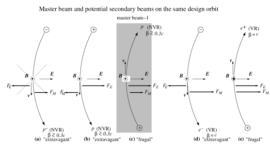
Fields are “cylindrical” electric and, superimposed, uniform magnetic . The bend radius is . Terminology is needed to specify the relation between electric and magnetic bending: Cases in which both forces cause bending in the same sense will be called “constructive” or “frugal”; Cases in which the electric and magnetic forces subtract will be referred to as “destructive” or “extravagant”. There is a reason for the “frugal/extravagant” terminology to be favored. Electric bending is notoriously weak (compared to magnetic bending) and iron-free (required to eliminate hysteresis) magnetic bending is also notoriously weak. As a result an otherwise-satisfactory configuration can be too “extravagant” to be experimentally feasible.
A design particle has mass and charge , with electron charge and (or some other integer). These values produce circular motion with radius , and velocity , where the motion is CW (clockwise) for or CCW for . With being the cylindrical particle position coordinate, the angular velocity is .
To limit cases we consider only electrons (including positrons) protons, deuterons, tritons, and helions; that is e-, e+, p, d, t, and h. The circulation direction of the so-called “master beam” (of whatever charge ) is assumed to be CW or, equivalently, . The secondary beam charge is allowed to have either sign, and either CW or CCW circulation direction.
Fractional bending coefficients and .
(In MKS units) and are commensurate forces, with the magnetic force relatively weakened by a factor because the magnetic Lorentz force is . Newton’s formula for radius circular motion can be expressed using the total force per unit charge in the form
| (3) |
Coming from the cross-product Lorentz magnetic force, the term is negative for backward-traveling orbits because the factor is negative. The “master” beam travels in the “forward”, CW direction. For the secondary beam, the factor can have either sign. For and , formula (3) reduces to the standard accelerator physics “cB-rho=pc/e”. For the formula incorporates the relative “effectiveness” of and .
Fractional bending coefficients and are then defined by
| (4) |
neither of which is necessarily positive. They satisfy .
Spin tune expressed in terms of and .
With being the angle between the in-plane component of beam polarization and the beam direction, the “spin tune” is defined to be the variation rate per turn of , expressed as a fraction of . Spin tunes in purely electric or purely magnetic rings are given by
| (5) |
With superimposed fields, the spin tune can be expressed in terms of the fractional bending coefficients,
| (6) |
The “magic energy” condition.
Superimposed electric and magnetic bending permits beam spins to be frozen “frugally”; i.e. with a ring smaller than would be required for all-electric bending. The magic requiremment is for spin tune to vanish;
Solving for ,
| (7) |
For example, with proton anomalous moment , trying , we obtain which agrees with the known proton 233 Mev kinetic energy value in an all-electric ring. For protons in the non-relativistic limit, and . The magic electric/magnetic field ratio is
| (8) |
Wien filter spin-tune adjustment.
Superimposed electric and magnetic bending fields allow small correlated changes of and to alter the spin tune without affecting the orbit. Being uniformly-distributed, appropriately matched electric and magnetic field components added to pre-existing bend fields can act as a (mono-directional) “global Wien filter” that adjusts the spin tune without changing the closed orbit. Replacing the requirement that and sum to 1, we require , and obtain, using the same fractional bend formalism, for a Wien filter of length the spin tune shift caused by a Wien filter of length-strength product is given by
| (9) |
For “global” Wien filter action by the bends of the entire ring, is to be replaced by .
16.3 “MDM comparator trap” operation
Dual beams in a single ring.
This section digresses temporarily to describe the functioning of dual beams in the same ring as a “spin tune comparator trap”. A “trap” is usually visualized as a “table-top apparatus”. For this paper “table-top radii” of , , or , meters (or rather curved sectors of these radii, expanded by straight sections of comparable length) are considered.
Gabrielse[8] has (with excellent justification) boasted about the measurement of the electron magnetic moment (with 13 decimal point accuracy) as “the standard model’s greatest triumph”, based on the combination of its measurement to such high accuracy and on its agreement with theory to almost the same accuracy. Though other magnetic moments are also known to high accuracy, compared to the electron their accuracies are inferior by three orders of magnitude or more. One purpose for a spin-tune-comparator trap would be to “transfer” some of the electron’s precision to the measurement of other magnetic dipole moments (MDM’s). For example, the proton’s MDM could perhaps be determined to almost the current accuracy of the electron’s.
Different (but not necessarily disjoint) co- or counter-circulating beam categories include different particle type, opposite sign, dual speed, and nearly pure-electric or pure-magnetic bending. Cases in which the bending is nearly pure-electric are easily visualized. The magnetic bending ingredient can be treated perturbatively. This is especially practical for the 14.5 MeV electron-electron and the 233 Mev proton-proton counter-circulating combinations.
Storage of different beam types in the same ring is illustrated in Figure 1. As explained in the caption, the bending can be either frugal or extravagant (i.e. constrictive or destructive). For a given particle type, if the clockwise (CW) bending is frugal, the counter-clockwise (CCW) bending is extravagant. For stable orbits the net radial force has to be centripetal. For the three cases described in this paper, the electric force magnitude exceeds the magnetic force magnitude. This means that only positive particle beams can be stable.
Eversmann et al.[4] have demonstrated the capability of measuring spin tunes with high accuracy. By measuring the spin tunes of beams cirulating in the same ring (not necessarily simultaneously) the MDM’s of the two beams can be accurately compared.
Sensitivity to imperfections.
So far only perfect apparatus has been considered. Here we comment on imperfections. The main attribute to be claimed for the spin tune comparator will be its relative insensivity to imperfections. Whatever validity is claimed will come from a combination of (1) basing parameter determinations only on frequency measurement, (2) accurate knowledge of the MDM’s, and (3) on the degree to which the spatial orbits of co- or counter-circulating beams are constrained to be identical to high accuracy. Also important will be the degree to which the ratio of electric to magnetic field is constant around the ring.
(To be shown shortly) radial positioning errors are not a serious concern but requiring the design orbits to be accurately planar (i.e. lying in a single horizontal plane) markedly improves the MDM (and later the EDM) measurement accuracy.
The reason for controlling vertical orbit excursions to better accuracy than horizontal has to do with spin precession control. Let us assume that element positions are established initially to m accuracy horizontally, and m accuracy vertically. Corresponding angular precision tolerances of about one-tenth milliradian horizontally and one-hundredth milliradian vertically will also be assumed.
Quoting G. Decker from 2005[9] “Submicron beam stability is being achieved routinely at many of these light sources in terms of both AC (rms 0.1 - 200 Hz) and DC (one week drift) motion.” For fairly-smooth orbits, if the orbits are that close at all BPM locations, they will be almost that close everywhere. With both spin tunes accurately measured, and their MDM’s known, the average circumference uncertainty will be dominated by spin tune measurement inaccuracy, which could correspond to 11 decimal point circumference accuracy.
In any case it is the circumference differences rather than the individual circumferences that will govern the accuracy of the spin tune comparator. After nulling all BPM differences, the CW and CCW circumferences will then be equal to about 13 decimal places.
With revolution period known “perfectly” from RF frequency measurement, and average velocity known “perfectly” from frozen spin and accurately known MDM, even the absolute circumference value will be known to high accuracy.
Spin tune invariance and spin tune comparator trap precision
By Eqs. (5) spin tunes and depend only on and but not on bend radius . This implies, for planar orbits, that spin tunes are conserved constants of the motion, independent of horizontal steering errors—assuming, of course, that all ring components stay rigidly fixed in place, and with unchanged strengths.
But (because of commutativity failure for rotations around non-parallel axes) vertical steering errors prevent the spin tune formulas from being universally valid conservation laws. Even so, from up-down symmetry, one expects the change in spin tune caused by a vertical deflection angle to be proportional to . By limiting the magnitudes of vertical deflection angles to be less than, say , one can expect the spin tunes and to be independent of lattice errors to, e.g. 14 decimal place accuracy. Knowing the spin tunes and values of both beams precisely, and knowing the MDM of the particles in one of the beams, allows the MDM of particles in the other beam to be determined to high accuracy.
This is how a “spin tune comparator trap” can compare MDM’s precisely. Parameter tolerances for EDM measurement will be comparble to those discussed in the previous section.
16.4 Secondary beam solutions
Analytic formulation.
Assume the parameters of a frozen spin master beam have already been established. As well as fixing the bend radius , this fixes the electric and magnetic bend field values and . A further constraint that needs to be satisfied for secondary beam operation is implicit in the equations already derived. To simplify the formulas we make some replacements and alterations, starting with
| (10) |
The mass parameter will be replaced later by, , , , , etc., as approppriate for the particular particle type. These changes amount to switching the energy units from joules to electron volts and setting .
The number of ring and beam parameters can be reduced by forming the combinations
| (11) |
After these changes, the closed orbit condition has become
| (12) |
an equation to be solved for secondary beam momentum . Any solution meets the requirement for spin tune comparator functionality, but not yet, in general, the doubly-magic, vanishing-spin-tune condition.
Any stable secondary beam orbit has to satisfy this equation but, because the electric and magnetic field values have been squared, not every solution of the equation has electric and magnetic field values that match the signs or magnitudes of the field values and constrained by the primary beam. So solutions of Eq. (12) have to be culled for consistency. The bending force has to be centripetal and consistent with bending in a circle of radius .
By construction the already-established existence of a stable master beam implies the existence of a real, CW (i.e. ) solution of the equation, say with mass . We look for other stable solutions, say with mass and momentum , for which there are no parameter changes whatsoever, neither in nor , nor in the sign or magnitude of the bend radius of curvature.
For spin tune comparator functionality, satisfying Eq. (12) is sufficient for finding compatable dual beam parameters, including determining their spin tunes to the high precision with which the anomalous magnetic moments are known.
If anti-protons, anti-deuterons, or other anti-baryons were experimentally available, the flexibility provided by Eq. (12) would be especially useful. The TCP combination of time, charge, and parity symmetry transformations would then provide TCP-matched solutions of the equation. But the only available negative particle is the negative electron, so TCP invariance applies usefully only to beam combinations containing an electron or a positron beam.
Limiting particle types to positron, proton, deuteron, tritium, and helions, a fairly comprehensive list of promising “doubly-magic candidate” solutions has been produced, satisfying these requirements, including the requirement that the master beam satisfy the magic beam condition.
For EDM measurement functionality the further constraints to be met are severe. With parameters established and set such that the “master beam” is magic, the only remaining free parameter is the secondary beam energy. Doubly magic solutions are sought by varying this energy (always constraining the primary beam to satisfy the spin condition 7). As well as meeting the vanishing spin tune condition, the energy also has to be such that beam production and handling is practical, and high quality polarimetry is available.
16.5 Three practical doubly-magic solutions
Promising doubly-magic solutions.
Several doubly magic beam pairs have been discovered. For this paper just three cases are considered. Their parameters are given in Table 1. Details are given in the table caption and case by case explanations are given in the sequel.
Eq. (12) has been solved with MAPLE to produce Table 1. (Intended only for checking derived results, and otherwise unreliable) the numerical anomalous magnetic moment values used have been:
| (13) |
| r0 | beam1 | KE | E0 | B0 | beam2 | KE2 | pc2 | QS2 | |
| m | GeV | V/m | T | GeV | GeV | ||||
| (b) PERTURBED DOUBLY-MAGIC PROTON-PROTON (nominal all-electric ring | |||||||||
| 50 | CW p | 0.2328 | 8.386e+06 | 1.6e-08 | 1 | CCW p | 0.2328 | -0.7007 | -2.144e-06 |
| CW p | 0.2328 | 0.7007 | -1.024e-15 | ||||||
| (c1) DOUBLY-MAGIC PROTON-POSITRON (promising new option | |||||||||
| 20 | CW p | 0.08663 | 6.355e+06 | 0.016 | 0.766 | CCW e+ | 0.03009 | -0.0306 | 5.000e-06 |
| (c2) DOUBLY-MAGIC POSITRON-PROTON (inverse of (c1)) | |||||||||
| 20 | CW e+ | 0.03009 | 6.355e+06 | -0.016 | 4.155 | CCW p | 0.08664 | -0.4124 | 5.842e-05 |
| (q1) DOUBLY-MAGIC HELION-PROTON (JEDI currently-capable option) | |||||||||
| 10 | CW h | 0.03924 | 5.265e+06 | -0.028 | 1.351 | CCW p | 0.03859 | -0.2719 | -6.173e-06 |
| (q2) DOUBLY-MAGIC PROTON-HELION (inverse of (q1)) | |||||||||
| 10 | CW p | 0.03859 | 5.265e+06 | 0.028 | 0.6958 | CCW h | 0.03924 | -0.4711 | 1.245e-05 |
Example (b) is perturbatively close to the already-known, singly-magic, all-electric solutions for protons. Examples (c1) and (c2) are doubly-magic solutions with positron and proton beams; the dually tabulated cases make the point that either beam can be interpreted as being the “master beam”. Example (q1) and (q2) show doubly-magic solutions with proton and helion beams.
Perturbative variant of the nominal all-electric ring.
Case (b) in Table 1 represents the all-electric frozen-spin proton ring which, up to now, has been implicitly anticipated to be the ultimate apparatus for measuring the proton EDM. With its detailed features not yet understood this ring has sometimes been called the “holy grail” ring. Not intentionally pejorative, this language has been intended to acknowledge the significant uncertainties concerning the detailed properties of such a ring. In the table this ring is now referred to as the “nominal all-electric ring”.
In fact, case (b) is already a more realistic representation of the all-electric ring in the sense that some residual non-vanishing vertical magnetic field will be inevitable, even in an all-electric ring. This will require simultaneously-frozen-spin beam energies to have slightly different energies in all cases.
With distributed electric and magnetic fields, using Eq. (9) to describe the performance of the entire ring as a Wien filter, it will not be difficult to meet the doubly-magic condition, even in the presence of extraneous weak vertical magnetic field. In itself, this would not justify distributed magnetic field, however, as the same trimming could be done with a short local Wien filter.
However the “perturbative” solutions (available also for all-electric electron, triton, and carbon 13 frozen spin rings) are very robust in the sense that the superimposed magnetic field can be varied over a large range while preserving the doubly-magic capability. This opens up the possibility of investigating systematic EDM errors by varying the magnetic bending fraction by a large factor.
This robust property applies uniquely to perturbations away from an all-electric ring. (In this case only) the structure of Eq. (12) guarantees that there is a continuum of doubly-magic solutions in the vicinity of the all-electric condition. With counter-circulating beams of the same particle type, if the bending is frugal for one beam it is necessarily extravagant for the other. But, since the sign of reverses at the all-electric point, the continuity of solutions of Eq. (12) guarantees the existence of a continuum of doubly-magic solutions in this vicinity. This is the justification for attaching “perturbed” to the name of case (b).
There is a complication concerning RF frequency, in that slightly different beam velocities will cause either slightly different orbits or slightly different revolution periods. For slow particles, such as protons, this may require running on different harmonics of a single RF cavity. For positrons, because they are fully relativistic, this would probably be impractical, and the orbits would have to differ slightly. This RF issue is addressed explicitly beow in the discussion of proton-helion case (q1).
Proton-positron doubly-magic solution.
From the point of view of greatest promise for absolute EDM determinations, case (c1) (with equivalent case (c2)), for proton and positron beams, seems to be the most promising case. It enables measurement of the difference between a master beam containing protons and a secondary beam containing positrons.
Canceling the Koop wheel roll rate of the secondary beam containing positrons cancels the radial magnetic field (under the assumption that the positron EDM is negligibly small). This allows the primary beam Koop wheel roll rate to serve as a measurement of the proton EDM.
As well as providing a clean, frequency difference measurement of the proton EDM, the beams can circulate simultaneously. Because positron and baryon velocities differ by an order of magnitude, it is probably impractical for the acceleration to be provided by harmonics of a single RF cavity; dual RF systems will be needed.
A major impediment in this case is the low analysing power of existing polarimetry methods for electrons (of either sign). To remove the “holy grail” qualification in this case will require the development of resonant electron polarimeter. This limitation is discussed further below. Achieving non-destructive, high analysing power electron polarimetry seems likely to be the only remaining major impediment to using EDM measurement to test the “standard model” of particle physics.
Helion-proton solution, JEDI-capable option.
From the point of view of earliest detection of physics beyond the standard model, case (q1) (with equivalent case (q2)) for proton and helion beams, seems the most promising. Like the doubly-magic baryon-positron pair solutions, doubly-magic, different-type baryon-baryon pairs can be used to obtain EDM differences. A doubly-magic triton/proton solution has been found, but it requires electric fields that are probably unachievable, even in the largest ring currently under consideration.
However, by fortuitous accident of their anomalous magnetic moments, there is a doubly-magic helion/proton solution (q1) (with equivalent (q2)) that needs only a small ring. (The development of a polarized helion beam at BNL is described by Huang et al.[18].) For this case radius has been taken in the table, in round numbers, to be 10 m.
The (q1) case has a CW, frugal bending solution for protons as master beam, with a CCW, extravagant bending helion beam as secondary beam. Carbon scattering asymmetry polarimetry will presumeably be used for both beams.
With a single RF cavity, to account for the different proton and helion velocities, the RF harmonic numbers can be 107 and 180, resulting in revolution period fractional difference of .
What makes this doubly-magic proton-helion option exciting is that, in the near future, using only currently-established experimental techniques, an upper limit for the EDM of baryons can be substantially reduced from current limits, possibly even to a level capable of demonstrating “physics beyond the standard model”. Some aspects of this ring are described in the EDM prototype chapter of the present report, along with other applications of that proposed ring.
16.6 Gravitational effect EDM calibration
Various authors[11][12][13] have pointed out that general relativity (GR) introduces effects that could be measureably large in proposed EDM rings. László and Zimborás[10] calculate the GR influence on storage rings designed for EDM measurement. The GR effect mimics the EDM effect. Mistaken attribution to proton EDM produces a spurious proton EDM value of approximately e-cm. This is about thirty times greater than the precision anticipated for the all-electric, 233 MeV ring originally contemplated and not inconsistent with an Orlov, Flanagan, Semertzidis[13] estimate. It is an accuracy that should be achievable with a small EDM prototype ring.
In a private communication, László and Zimborás have kindly provided their result for the precession of the polarization vector ;
| (14) |
where is the velocity over speed of light of the particle, is its Lorentz factor, is its magnetic moment anomaly, is the gravitational acceleration vector of the Earth, and is the speed of light, along with the interpretive comment “It is seen that the pertinent gravitational contribution is a beam-radial precession vector, i.e. causes a contribution to the vertical polarizational buildup if the initial polarization was longitudinal.”
Comparing Eqs. (2) and (14) one notes that the Koop roll and the GR roll depend differently on the parameters; for example, in an all-electric ring, their dependence on velocity reversal is opposite. This will help in subtracting the GR effect. Once under control, the GR signal will serve as a valuable calibrator of the EDM detection apparatus. The absolute level of this calibration signal will be at the optimistic (i.e. large EDM value) end of the range of plausible “physics beyond the standard model”.
16.7 The need for non-destructive resonant polarimetry
Arthur Schawlow, co-inventor of the laser, is credited with the advice to “Never measure anything but frequency”. Though not emphasized up to this point, this principle is implicit in the present paper. Though this advice is often accepted, its basis is rarely explained.
In our case the EDM signal at the end of an hour-long run may be an EDM-induced beam polarization angular difference of, say, a milliradian, between initial and final beam polarization orientations. Expressed as a fraction of a complete revolution of the beam polarization, this is . For any single run this angular shift is likely to be comparable with the difference uncertainty of destructive polarimetry initial and final orientation measurements. (Then by averaging over, say, one thousand runs, the statistical error can be reduced by a factor of thirty or so. )
Consider the same hour-long run with non-destructive resonant polarimetry, assuming, for the moment, the polarimeter natural resonant frequency to be the same as the beam revolution frequency. When sensed instantaneously, the resonator phasor angular advance from run beginning to run end is likely to approximately match the difference of the previous paragraph, with “phase noise” having yielded approximately the same uncertainty. But (absent other sources of low frequency noise) after non-destructive averaging the resonator phase for few-minute intervals at both beginning and end, the per-run phasor angular advance can be determined with far less uncertainty than is possible with destructive scattering asymmetry.
This has not yet included two other factors that favor resonant polarimetry. One of these factors is that the whole beam is measured at both beginning and end. With destructive polarimetry, at best, orientation of only half of the beam is measured at run beginning; the other half of the beam is measured at the end.
The other advantage of resonant polarimetry would be that, in practice, the resonant polarimeter frequency will be in the GHz range, 1000 times higher than the revolution frequency. Generally speaking, absolute precisions seem to increase inexorably as technological advances allow processing at ever higher frequaencies. But it would not be legitimate to therefore claim a 1000 times higher precision, without having acquired a deeper understanding of the issues. In our case, for example, at every instant of time there will be a significantly large spread of particle revolution frequencies, more or less centered on a frequency that is known with exquisite accuracy from the known beam magnetic moments. Without having a clear understanding of the fluctuations and averaging it is hard to refine the determination of the phase precision of resonant polarimetry.
Regrettably, the entire discussion of resonant polarimetry up to this point has been “counting chickens before they’re hatched”. Resonant polarimetry has never, in fact, been demonstrated to be practical. However, theoretical calculations (admittedly due largely to the present author) based on the Stern-Gerlach interaction, have shown that the regular passage of bunches of polarized electrons through a cavity should produce detectably-large cavity excitation[14][15][16]. The latter two of these references describe, in considerable detail, experiments being planned to test both transverse and longitudinal polarimetry, using a polarized electron linac beam in the CEBAF injection line at the Jefferson Laboratory in Newport News, Virginia. Within a few years tests like these should have resolved the issue conerning the practicality of Stern-Gerlach polarimetry for electrons.
The proton’s magnetic dipole moment is three orders of magnitude smaller than the electron’s. In the absence of noise background a proton Stern-Gerlach signal reduced by this factor, would still be detectably large but, without extremely narrow band lock-in detection, the proton polarimetry signal is likely to be swamped by noise. This makes phase-locked-loop proton beam polariization control based on resonant polarimetry likely to fail, even if resonant electron polarimetry has been demonstrated to succeed. This is my expectation.
It is this expectation that makes the doubly-magic proton-positron combination for measuring baryon EDM’s seem especially important. With a positron beam phase-locked to resonant Stern-Gerlach polarimeters (both transverse and longitudinal) the Koop wheel manipulations, so optimistically assumed in the present paper, should, indeed be extremely precise for the positron beam.
By exploiting the known relation between positron and proton MDM’s, it should then be possible to freeze the co-rotating proton spins just by controlling the positron beam spin tune and phase. With the frequency and phase of the proton beam magnetization then known to such high precision, the frequency filtering of a proton beam Stern-Gerlach resonator can be selective to reject the noise which would, otherwise, prevent the accurate resonant determination of the magnetization signal.
Only when non-destructive positron polarimetry has been successfully demonstrated will it be legitimate to remove the “holy grail” designation from the case (c1) positron-proton doubly-magic EDM ring design, to make the discovery of physics beyond the standard model likely.
16.8 The EDM measurement campaign
The majority of my work in the storage ring EDM area for the last several years has been performed during, and in connection with, my stays at the IKP Institute for Nuclear Physics of Forschungszentrum, Juelich.
During 2018, in response to a CERN invitation, an EDM task force at the IKP laboratory has been performing a feasibility study of measuring electric dipole moments, especially of the proton. A full report is due by the end of the year. The initial motivation for building a small prototype EDM ring was to demonstrate the ability to store enough protons to enable an EDM measurement in a storage ring with predominantly electric bending. A preliminary report was issued after the first quarter of 2018[17]. The present paper has been co-ordinated with this task force planning.
As well as developing long term planning, an important thrust of the task force has been to advocate the immediate development of designs for a “small” EDM prototype storage ring. The doubly-magic design should have a major impact on motivation. This design eliminates the need to use the vertical separation of counter-revolving beam orbits to suppress radial magnetic field. Previous EDM designs have required excruciatingly small vertical betatron tune in order to enhance this “self-magnetometry” sensitivity to vertical beam separation of counter-circulating beams. The coorrespondingly weak focusing was expected to set a small limit on the proton beam intensity.
The doubly-magic EDM ring design transfers this self-magnetometry resonsability to a secodary frozen spin beam (with the admitted cost of measuring EDM differences rather than absolute EDM values). Elimination of the need for ultraweak focusing should enable the beam current intensities to be limited only by previously-encountered understood effects. This will permit the storage ring to have much stronger, alternating gradient focusing, which can be expected to increase the achievable proton beam current substantially.
Another motivation for building a small prototype EDM ring has been to develop and demonstrate the performance of instrumentation and procedures that will be needed for a subsequent larger ring. These applications are implicit in the examples of Table 1. Especially relevant is the doubly-magic combination of case (q1), which can be used to measure the difference of proton and helion EDM’s, This can be done using carbon scattering polarimetry of the type that has been developed, and is already in service, in the Juelich COSY ring. As already stated, any measureably large difference between proton and helion EDM’s would constitute physics beyond the standard model.
Important contributions by my EDM collaborators need to be acknowledged, especially to Sig Martin and Helmut Soltner for detailed discussions of implementation practicalities. Acknowledgements are also due to Maxime Perlstein for insisting on a less confusing treatment of the orbitry, to Eanna Flanagan and Andras Laszlo for communications concerning general relativistic effects, and to Andreas Wirzba for conveying and explaining a GR analysis by Kolya Nikolaev.
References
- [1] J. Farley et al., New Method of Measuring Electric Dipole Moments in Storage Rings, Phys. Rev. Lett., 052001, 2004
- [2] Y. Semertzidis for the Storage Ring EDM Collaboration, A Proposal to Measure the Proton Electric Dipole Moment with e-cm Sensitivity, October, 2011
- [3] I.A. Koop, Asymmetric energy colliding ion beams in the EDM sorage ring, Paper TUPWO040, in Proceedings of IPAC2013, Shanghai, China, 2013. When beginning to prepare the present paper, though aware of the “Koop spin wheel”, we had not realized that the shared beam EDM approach, not including the doubly-magic possibility, nor the possibility of electron or positron secondary beam, nor the spin tune comparator functionality, had been proposed by Koop five years earlier.
- [4] D. Eversmann et al., New method for a continuous determination of the spin tune in storage rings and implications for precision experiments, Phys. Rev. Lett. 115 094801, 2015
- [5] N. Hempelmann et al., Phase-locking the spin precession in a storage ring, P.R.L. 119, 119401, 2017
-
[6]
I. Koop, Spin wheel—a new method of suppression of spin decoherence in the EDM storage rings,
http://collaborations.fz-juelich.de/ikp/jedi/public-files/student_seminar/
SpinWheel-2012.pdf - [7] A. Wolski, Beam Dynamics in High Energy Particle Accelerators, Eq. (3.175), Imperial College Press, 2014
- [8] G. Gabrielse, The standard model’s greatest triumph, Physics Today, p. 24, December, 2013
- [9] G. Decker, Beam stability in synchrotron light sources, Proceedings of Lyon, France, DIPAC 2005
- [10] A. László and Z. Zimborás, Quantification of GR effects in muon g-2, EDM and other spin precession experiments, Class.Quant.Grav 35, 175003, 2018
- [11] Y. Obukov, A. Silenko, and O. Terayev, Manifestations of the rotation and gravity of the Earth in high-energy physics experiments, Phys. Rev. D94, 2016
- [12] Y. Obukov, A. Silenko, and O. Terayev, Manifestations of the rotation and gravity of the Earth in spin physics experiments, Int. J. Mod. Phys. A31, 1645030, 2016
- [13] Y. Orlov, E. Flanagan, and Y. Semertzidis, Spin rotation by Earth’s gravitational field in a “frozen- spin” ring, Phys. Lett. A376, 2822, 2012
- [14] R. Talman, The Electric Dipole Moment Challege, IOP Publishing, 2017
- [15] R. Talman, B. Roberts, J. Grames, A. Hofler, R. Kazimi, M. Poelker, and R. Suleiman, Resonant (Longitudinal and Transverse) Electron Polarimetry, XVii International Conference on Polarized Sources, Targets, and Polarimetry, Daejeon, Republic of Korea, 2017
- [16] R. Talman, Prospects for Electric Dipole Moment Measurement Using Electrostatic Accelerators, Reviews of Accelerator Science and Technology, A. Chao and W. Chou, editors, Volume 10, 2018, not yet in print
- [17] JEDI EDM task force “Easter Report”, unpulished internal report, Institute for Nuclear Physics of Forschungszentrum, Juelich, Germany, April 30, 2018
- [18] H, Huang et al., Optics setup in the AGS and AGS booster for polarized helion beam, Paper WEPRO071 in the Proceedings of Dresden, Germany, IPAC2014