Phase-field study of crack nucleation and propagation in elastic - perfectly plastic bodies
Abstract
Crack initiation and propagation in elastic - perfectly plastic bodies is studied in a phase-field or variational gradient damage formulation. A rate-independent formulation that naturally couples elasticity, perfect plasticity and fracture is presented, and used to study crack initiation in notched specimens and crack propagation using a surfing boundary condition. Both plane strain and plane stress are addressed. It is shown that in plane strain, a plastic zone blunts the notch or crack tip which in turn inhibits crack nucleation and propagation. Sufficient load causes the crack to nucleate or unpin, but the crack does so with a finite jump. Therefore the propagation is intermittent or jerky leaving behind a rough surface. In plane stress, failure proceeds with an intense shear zone ahead of the notch or crack tip and the fracture process is not complete.
1 Introduction
The variational fracture field approach following (Bourdin et al., 2000, 2008) has emerged as a powerful tool for the study of fracture in brittle materials. This approach is based on a regularization of the variational formulation of brittle fracture by (Francfort and Marigo, 1998) following (Ambrosio and Tortorelli, 1990). The crack set is approximated by a diffuse region described by a smooth fracture field variable, and an energy functional that approximates (in the sense of Gamma convergence) the fracture energy functional is minimized subject to boundary conditions. This framework has now been widely used in various situations and also described as phase-field approach and the gradient damage approach (see for example, (Pham et al., 2011; Klinsmann et al., 2015; Pham et al., 2017; Zhang et al., 2017)).
Very few materials are brittle, and therefore the study of elastic - plastic fracture is a subject with a rich history; see (Hutchinson, 1989) for a comprehensive review. Rice and his collaborators (Rice, 1968; Rice and Sorensen, 1978)) studied the stress and strain fields in the vicinity of a stationary crack, and used the knowledge of these fields to understand the role of plasticity in enhancing fracture toughness. In recent years, a damage model going back to (Gurson, 1977) and (Needleman and Tvergaard, 1987) has been widely used to study failure in elastic - plastic materials. There is an understanding that cracks are blunted by the formation of a plastic zone around the crack tip, that high triaxiality ahead of the crack tip leads to voids and the crack propagates by the coalescence of voids (see (Benzerga and Leblond, 2010) and the citations there).
Given its success in describing brittle fracture and given the importance of ductile failure, it is natural that the variational fracture field approach be extended to elastic - plastic materials, and this has been proposed by (Alessi et al., 2014, 2015; Ambati et al., 2015; de Borst et al., 1999; Miehe et al., 2015, 2016; Nedjar, 2001; Reusch et al., 2003; Alessi et al., 2014, 2015; Tanne, 2017), who combined the (Bourdin et al., 2008) functional with a scaled plastic dissipation functional. They studied various aspects of the model including stability and homogeneous crack initiation in a one-dimensional medium as well as a uniaxial tensile specimen. (Miehe et al., 2015, 2016) use a similar formulation though it is framed in the context of balance laws, and study selected two dimensional problems in infinitesimal and finite deformation. (Ambati et al., 2015) use a different functional where the plastic strain modifies the elastic stiffness of the material.
This paper adopts the formulation of (Alessi et al., 2014, 2015), and implements it numerically to study crack nucleation and crack propagation in Mode I in both plane strain and plane stress. Crack nucleation is studied in a specimen with a notch subjected to increasing displacement boundary condition while crack propagation is studied in a rectangular domain subjected to a surfing boundary condition. When the yield strength is high (compared to the nucleation stress of brittle fracture), plastic yielding is limited to a very small region around the crack tip, and the nucleation and propagation are broadly similar to those in brittle materials. This is consistent with the idea of small scale yielding.
The behavior changes for smaller yield strength. In plane strain, a plastic zone forms at the notch (respectively crack) tip thereby preventing nucleation at the notch (respectively pinning the crack). Eventually for a high enough value of applied load, the crack does nucleate (respectively gets unpinned). It does so by jumping through a finite distance both during nucleation and propagation. It gets pinned again by the plastic zone and the cycle repeats. In other words, the observed crack propagation in plane strain is always intermittent leaving behind a rough fracture surface.
The observation of jerky motion appears to be a departure from the arguments of (Rice and Sorensen, 1978; Hutchinson, 1989) and others. They compare a pinned crack (in an infinite medium loaded at infinity) and one that is steadily propagating, and show that the former has a smaller incremental energy release rate than that of the latter. They argue that if the pinned crack were to start propagating continuously with time, the energy release rate would increase monotonically thereby ensuring the incremental stability of this solution. The results here show that there is another solution to the problem – one where the crack jumps. The setting of rate independent, perfect plasticity means that one can have multiple solutions. Further incremental stability of a solution involving crack propagating continuously with time does not imply stability against a solution involving crack jumps.
The source of the intermittent crack growth is the fact that a region of intense hydrostatic (tensile) stress appears ahead of the pinned crack tip. This would suggest that a daughter crack would nucleate ahead of the crack tip and then propagate backwards to join the main crack. This happens instantaneously in the current rate-independent, perfectly plastic model and manifests itself as a crack jump. This understanding is consistent with the recent work cited in (Benzerga and Leblond, 2010) (see also, (DESCATHA et al., 1981; Beremin, 1981; Benzerga et al., 2016; Needleman and Tvergaard, 1987; Pineau et al., 2016)) who argue that voids would nucleate ahead of the crack tip and eventually coalesce. Further, the experimental observations of (Kobayashi and Giovanola, 1989) clearly shows the appearance of a daughter crack ahead of the main crack followed by coalescence albeit in a dynamical setting. Finally, the jerky motion results in a rough or dimpled crack surface and this is well established in fractography.
The situation in plane stress is different. A plastic zone forms at the crack tip and gradually extend ahead of it. Failure occurs by the formation of a region of intense shear due to the high deviatoric stress induced by the lack of confinement. This shear is accompanied by damage, but the fracture process is not complete. Note that the assumption of plane stress requires that the material be thin compared even to the process zone. Therefore, it is natural to wonder whether one encounters such situation in reality.
While the numerical implementation and the mechanisms they reveal are inherently interesting, a long term motivation to use both the insights from these mechanisms and numerical method to study crack propagation in heterogeneous elastic plastic materials. This is addressed in forthcoming work.
The paper is organized as follows. The formulation and the numerical method are described in Section 2, and a few useful results are recalled in Section 3. Crack nucleation in a notched specimen is studied in Section 4 while crack propagation under surfing boundary conditions is described in Section 5.
Notation. Underlined and double-underlined characters respectively denote vectors and second-order tensors. Blackboard letters indicate fourth-order tensors; symbol denotes the double-dot product operator. A superposed dot denotes the time derivative.
2 A variational phase-field approach
Consider a body occupying a domain in its reference configuration. Let denote the displacement field, the strain, the stress and the plastic strain.
Assuming elastic/perfectly-plastic behavior, the stress is confined to the set of admissible stresses related to the yield function . By the normality rule, the admissible rate of change of plastic strain is , and the plastic dissipation is
| (1) |
Clearly is homogeneous of degree one corresponding to perfect plasticity. In this work, the material is assumed to obey to a von Mises strength criterion with yield function and plastic dissipation
| (2) |
with and , where and are the deviatoric stress and strain-rate tensors, respectively, and is the von Mises strength.
Following (Bourdin et al., 2000, 2008), fracture is described by introducing a scalar regularized phase field with corresponding to the intact material and to complete fracture. This fracture field varies at a length-scale .
The fracture of elastic - perfectly plastic bodies subject to some boundary condition is given by the solution of a minimization problem (Alessi et al., 2015):
| (3) |
where the energy functional
| (4) |
Here, is the set of kinematically admissible displacement fields subject to the applied boundary condition, is the elastic modulus (taken to be homogeneous and isotropic in what follows) and is the critical energy release rate (which will be referred to as “toughness” with a slight abuse of terminology). The function ensures that corresponds to the intact material and to complete fracture with being a small residual stiffness. The latter, introduced for the sake of numerical convenience, has been proven not to have any significant influence on the obtained results (Bourdin et al., 2014). In this work, and . Finally, ensures that the yield strength is independent of the fracture.
In order to non-dimensionalize the equations, the fracture problem is recast in terms of the quantities
| (5) |
where is a characteristic length of the domain , , and are the typical values of the elastic moduli and of the toughness parameter of an elastic material commonly used in engineering practice, and is the correspondingly-computed nucleation stress. For the sake of notation, the superposed tilde in Eq. (5) is dropped in the following.
The minimization in Eq. (3) is not trivial, since the regularized total energy is non-convex. Nevertheless, noticing that is separately convex in , and , the minimization problem is solved by an iterating on three different sub-problems until convergence is reached, and according to the following two procedures:
-
•
AUP: for each time-step , the functional is minimized with respect to any kinematically-admissible displacement and plastically-admissible strain while holding the damage variable fixed. Then, fixing and , the energy is minimized with respect to , under the irreversibility condition .
-
•
UPA: for each time-step and for a given displacement field , the functional is minimized with respect to the plastic strain and the damage variable , respectively subjected to the normality rule and to the irreversibility condition. Then, given and , a further minimization is performed on the displacement field under the kinematic admissibility constraint.
The problems are implemented using linear finite elements. The constrained minimization with respect to the phase-field variable is implemented using the variational inequality solvers provided by PETSc (Balay et al., 1997, 2013a, 2013b). The minimization with respect to displacement field is a linear problem, solved by using preconditioned conjugated gradients. The minimization with respect to the plastic strain is reformulated as a constrained optimization via SNLP solvers111Available at http://abs-5.me.washington.edu/snlp/ and at https://bitbucket.org/bourdin/snlp.. All computations are performed by means of the open source code mef90222Available at https://www.bitbucket.org/bourdin/mef90-sieve..
3 Preliminaries
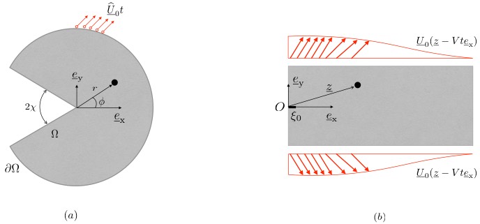
The computational approach is used to study two problems shown in Figure 1. The first is a specimen with V-notch subjected to displacement boundary conditions to understand crack initiation and nucleation. The second is a rectangular domain subjected to a surfing boundary condition to understand crack propagation. In the figures in the sequel, the plastic process zone is shown in green and represents the region where the accumulated equivalent plastic strain exceeds the value 0.1%, . Similarly the presence of fracture process is shown by shading the region where the fracture variable exceeds the threshold 0.1%, .
The energy release rate is computed via the -integral (Cherepanov, 1967; Rice, 1968) as
| (6) |
where , is the elastic energy density, is a contour surrounding the crack tip, and is the outward normal to . The contour is always chosen to be a outer boundary of the domain and away from any plastic region.
It is useful to recall two results from the linear elastic setting. First, the toughness computed via the variational phase-field approach (Bourdin et al., 2008) is increased by a factor that depends on the discretization so that the numerical critical energy release rate is
| (7) |
Second, crack nucleation depends on the regularization parameter . Specifically, in a uniaxial traction test, a crack is nucleated when the local stress equals the critical threshold (Pham et al., 2011)
| (8) |
Indeed, this allows one to fit the regularization parameter to the known critical stress of the material.
In the simulations that follow, the yield strength is described relative to the nucleation stress using the ductility ratio
| (9) |
As the yield strength is reduced compared to the nucleation stress , the material can plastically deform before a crack is nucleated. As such, and respectively correspond to quasi-brittle and ductile fracture.
4 Crack nucleation at stress singularities
This section studies the nucleation of cracks at a stress singularity following the approach of (Tanné et al., 2018) who did so in the context of elastic materials.
4.1 Setting
Consider a specimen occupying a domain consisting of a V-shaped notch, as shown in Figure 1a, in its natural reference state. The notch angle is with , such that the notch degenerates into a crack as and opens up into a straight edge as . The specimen is subjected to a proportional (time-scaling) displacement along its exterior boundary . By referring to a polar coordinate system emanating from the notch tip, the radial and tangential components of the displacement field are taken to be
| (10a) | ||||
| (10b) | ||||
where the prime denotes the derivatives with respect to , the function
| (11) |
and where is the exponent of the stress singularity at the crack tip computed by solving
| (12) |
Note that this displacement field corresponds to the leading order term in the asymptotic field near notch subjected to a far-field mode-I conditions (Leguillon and Sanchez-Palencia, 1987). Thus, this boundary displacement promotes the nucleation of a mode-I crack at the notch tip.
Numerical simulations are performed using the minimization procedure AUP in both plane stress and plane strain conditions. The non-dimensional parameters are chosen as follows: the Young modulus , Poisson ratio , toughness . The regularization length is chosen according to Eq. (8) to make the nucleation stress and the mesh size .
4.2 Crack initiation at a sharp notch
Plane stress.
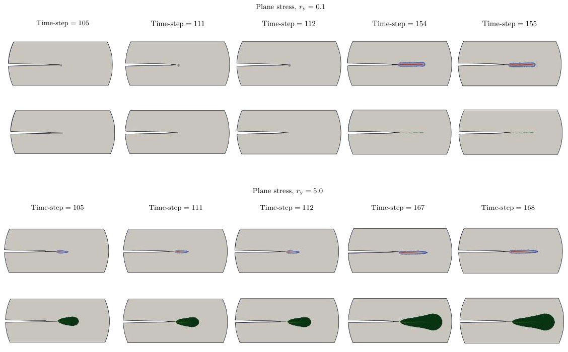
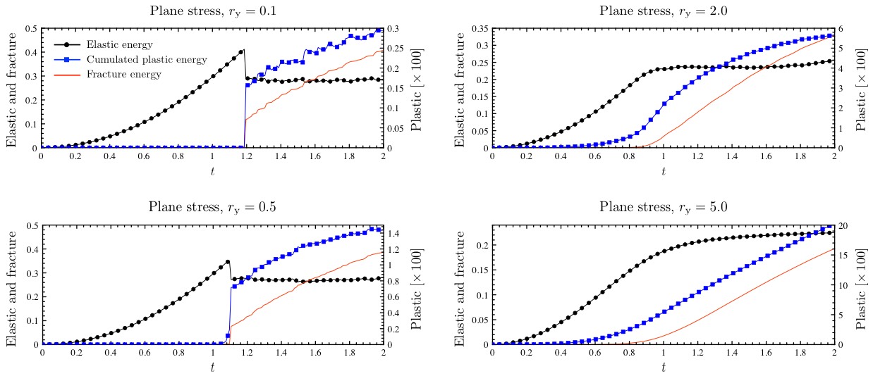
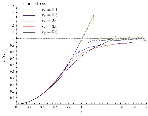
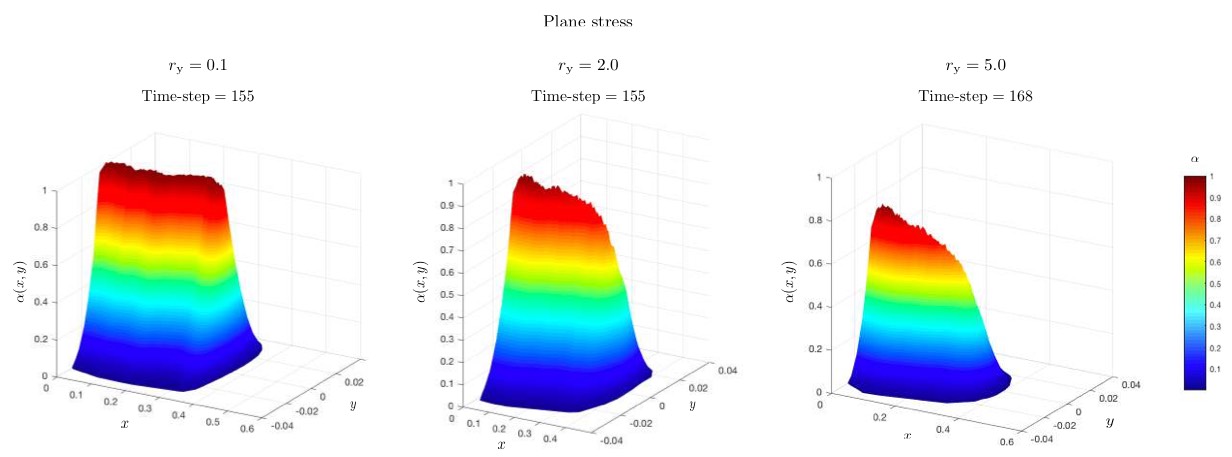
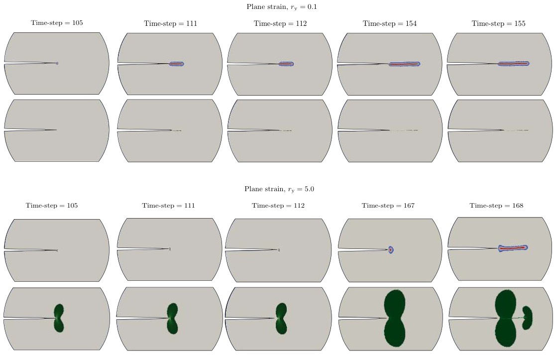
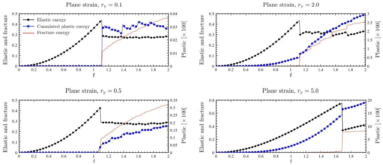
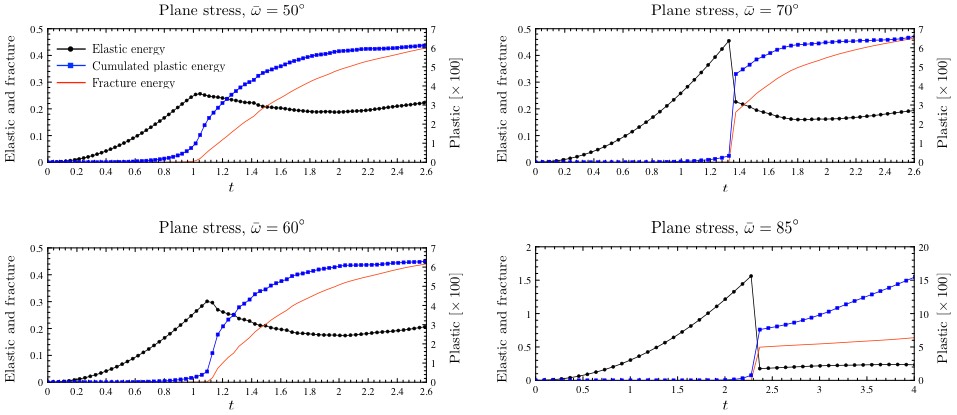
Figure 2 shows the evolution of fracture and plastic fields for a sharp notch with in plane stress conditions for various values of the ductility ratio . Figure 3 shows the evolution of the various energies and Figure 4 the energy release rate computed using the J-integral on the boundary. Figure 5 shows the fracture field for various ductility ratio.
In the quasi-brittle situation and , the equivalent plastic strain and fracture parameter are zero outside a region of radius at the notch tip at early times. This is also reflected in the zero fracture energy and plastic dissipation, and the linear growth of the energy release rate. At a critical time, a finite crack appears, accompanied by a sudden rise (respectively, reduction) of the fracture energy and plastic dissipation (respectively, elastic). The crack then grows steadily, the plastic zone is confined to a small region around the crack tip and the energy release rate is close to the toughness . In other words, the behavior is very similar to the purely elastic or brittle situation (Tanné et al., 2018).
The behavior changes in the ductile situation and . Plastic and fracture process zones appear soon after loading begins and grow steadily as the the load increases. This is also evident in the smooth increase in fracture energy and plastic dissipation. The energy release rate increases steadily and approaches the toughness, but does not reach that value. In fact, the fracture variable does not reach the value 1 indicating that the fracture process is not complete. In other words, a band of intense plastic deformation forms and continues to grow along with progress towards but not complete fracture.
There is also a curious cross-over in the energy release rate. Note in Figure 4 that at early stages, the energy release rate decreases with increasing ductility ratio . However, at some point, the energy release rate begins to reverse and eventually the energy release rate increases with increasing ductility ratio. It is important to remember that the energy release rate computed using the J-integral on the boundary includes both the work of fracture and plastic dissipation. Initially, the presence of plasticity impedes the fracture process and therefore the energy release rate is suppressed by ductility. However, the plastic dissipation is higher in the more ductile materials, and this eventually dominates the energy release.

Plane strain.
The same problem is studied in plane strain and the results are shown in Figures 6, 7, 8 and 9. The behavior in the quasi-brittle situation is similar to that of plane stress and the purely elastic case. However, the behavior in the ductile situation in plane strain is very different from that of plane stress. In plane strain, a small region of non-zero fracture field variable and plastic deformation forms early in the loading. The plastic zone continues to grow in two lobes either side of the mid-plane but the fracture field remains essentially fixed. This continues till the energy release rate exceeds the toughness of the material as well as the critical value of the quasi-brittle case. Then, at a critical load, the fracture field increases suddenly corresponding to the formation of a finite crack (note that the fracture field reaches the value one) and accompanied by a drop in the elastic strain energy. Continued loading creates a plastic zone near the crack tip but keeps the crack pinned at the same location and the energy release rate again begins to grow. This continues till the energy release rate reaches a different critical value when the crack suddenly jumps forward by a finite distance, and the elastic strain energy and energy release rate drop. The cycle then repeats. Importantly, note that the critical value of energy release rate required for crack initiation increases with ductility.
Summary.
Crack initiation at a sharp notch in quasi-brittle materials is similar to that in purely elastic brittle materials. However, the behavior changes for ductile materials. Further, the behavior in ductile materials is quite different in plane stress and plane strain. In the former, an intense plastic band accompanied by a fracture field region forms and grows smoothly ahead of the notch. Further, the fracture process is not complete. In contrast, in plane strain, the crack initiation and growth is impeded by plasticity and proceeds in an intermittent fashion. Further, the fracture process proceeds to completion. This difference reflects the difference in confinement. In plane stress, the lack of confinement leads to high deviatoric stress ahead of the notch/crack. This promotes plastic deformation which in turn promotes increase in the fracture field but not complete fracture. In contrast, in plane strain, the confinement limits the deviatoric stress ahead of the notch/crack but promotes it away from it. This results in a growth of the plastic zone that drains away energy from the fracture field. Thus, the crack is pinned; however, once it breaks free it does not see any pinning and therefore jumps through a finite distance.
4.3 Crack nucleation at a V-notch
A V-notch with a larger opening angle is considered next. The quasi-brittle behavior in both plane stress and plane strain is similar to the elastic case studied by (Tanné et al., 2018), and not discussed any further. In contrast, the ductile behavior is quite rich.
Plane stress.
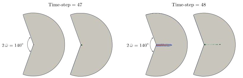
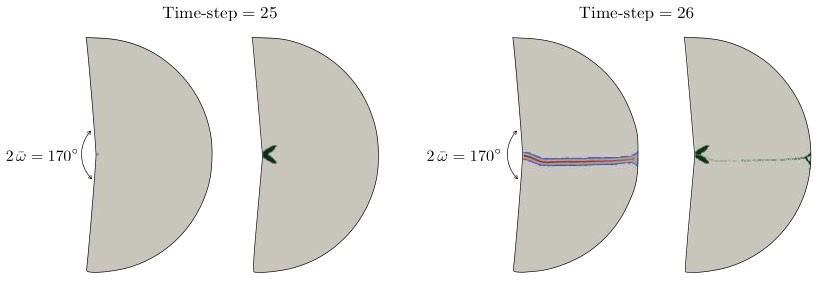
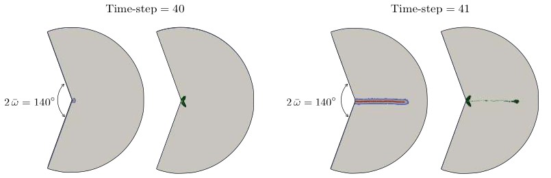
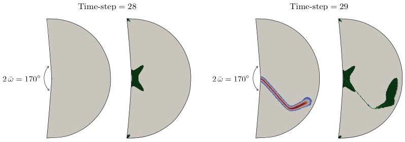
Figure 10(a) shows the evolution of the various energies for the case , , and in plane stress. For small notch opening angles, the evolution is similar to the earlier case of a sharp notch – i.e., an intense band of shear and fracture field appears ahead of the crack and grows smooth with increasing load. However, the initial growth of the fracture zone becomes more and more sluggish with increasing opening angle. This reflects that the stress concentration becomes weaker with increasing the notch angle. Indeed, for and , the fracture activity does not begin till a critical time. It proceeds smoothly once it begins and is accompanied with a smooth drop of elastic energy. The behavior transitions to that of pinning followed by sudden growth for larger notch opening angle as shown in the case of in Figure 10(b). In this case, the plastic and fracture zone is confined to the notch-tip till the load reaches a critical value when a finite fracture zone appears with a drop in elastic energy. As in the previous cases, the fracture does not go to completion (the figure is not shown). The fracture zone is pinned at further loading as a plastic zone appears and grows near the fracture tip. The behavior transitions again for higher . At when the notch opens to almost a straight edge, the fracture zone is no longer straight, but appears at a angle as shown in Figure 10(c).
Crack nucleation at a notch was studied extensively by (Tanné et al., 2018) in the brittle case. They introduced a generalized stress-intensity factor:
| (13) |
where is the order of the singularity in the displacement field of an elastic field around a notch. Since the hoop stress has a singularity of strength , this is well-defined independent of radius. In particular, note that this equals the stress in the case of a straight edge and the stress-intensity factor in the case of a crack. (Tanné et al., 2018) showed that a large amount of experimental and computational data in brittle fracture can be explained by postulating a crack nucleation criterion
| (14) |
where the critical value interpolates between and . A similar criterion was also shown to hold at bimaterial interfaces (Hsueh et al., 2018).
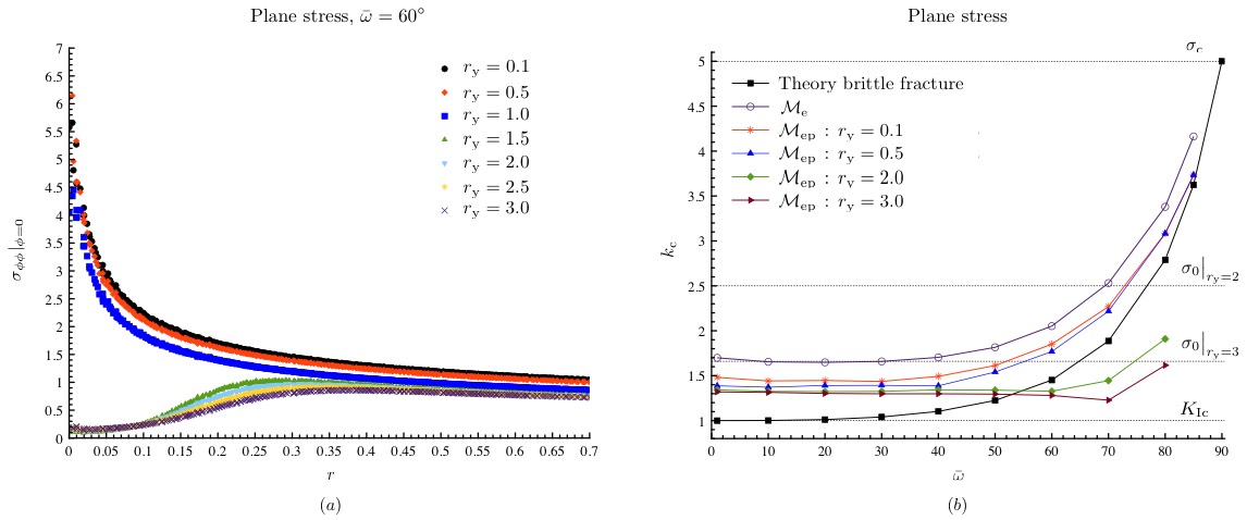
Figure 11(b) studies the applicability of this criterion in the elastic plastic materials in plane stress. This figure plots the critical value of computed as the value at the time-step just preceding the one where the fracture energy jumps or reaches the value . The behavior of the quasi-brittle case () is similar to the elastic case and follows (14). However, the behavior is dramatically different for the ductile situations. The reason for this can be found in Figure 11(a): the stress concentration at the notch tip disappears in the ductile case even for the sharpest notch. Therefore, critical is limited by the value dictated by shear failure, and is relatively independent of the notch opening angle.

Plane strain.
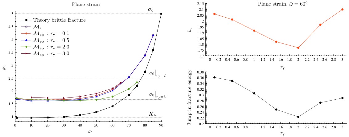
The plain strain situation is shown in Figure 12(a). As in the case of a sharp notch, there is a distinct nucleation event where a crack forms suddenly and with finite length. Further, the fracture always proceeds to completion. The plastic zone has the shape of two lobes just above and below the symmetry plane. Finally, for high notch opening angles, as one approaches the straight edge, the crack forms at angle (Figure 12(c)).
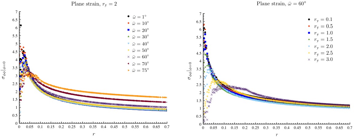
The behavior of the stress near the notch tip is shown in Figure 13(a). The ductility regularizes the stress field, but there is always a region of elevated stress in the vicinity of the notch tip. This contributes to the nucleation of a finite (complete) crack in plane strain. The critical value of the generalized stress intensity is shown in Figure 13(b). The behavior of quasi-brittle cases are similar to those of the brittle case. However, the behavior of the ductile cases are quite varied. The critical value drops and becomes independent of for ductility ratio , but begins to rise again with for higher values of ductility ratio. This is highlighted for the case where the behavior of vs. is non-monotone. The stress distribution for this situation is on the right of Figure 13(a). The plasticity regularizes the stress singularity, but a region of elevated stress remains and in fact spreads with increasing . This initially promotes crack nucleation till about . However, for higher ductility ratio the elevation in stress is minimal and this makes crack nucleation more difficult. This manifests itself in the non-monotone behavior.
Summary.
Crack nucleation at a V-notch in the quasi-brittle situation is very similar to that in purely elastic brittle materials. However, the behavior of ductile materials is different and rich. In plane stress, a region of intense plastic deformation accompanied by a fracture field forms and grows smoothly ahead of the notch for small notch angles. For large notch angles, the growth of the fracture field is inhibited till a critical load, and then proceeds either rapidly or suddenly. For very large notch angle, the plastic and fracture zone form at a angle. In all these situations, the fracture never proceeds to completion. In plane strain, a plastic zone forms near the notch tip that inhibits crack growth. A finite crack nucleates suddenly and the fracture process is complete in this crack. For notch opening angles, the critical generalized stress intensity when the crack forms behaves non-monotonically with ductility ratio due to the behavior of the stress field at the notch tip.
5 Crack propagation
This section studies the propagation of cracks subjected to surfing boundary conditions folllowing (Hossain et al., 2014).
5.1 Setting
Consider the rectangular domain of length and width , and the coordinate system shown in Figure 1(b). A pre-crack of length is present on the left as shown. The boundary of this domain is subjected to a time-dependent displacement boundary condition
| (15) |
where is some displacement field that opens the crack. Specifically, is taken to the asymptotic displacement associated with a mode-I crack (Zehnder, 2012),
| (16) |
where denotes the critical value of the stress-intensity factor in plane stress or plane strain conditions, and is an arbitrary non-dimensional scaling parameter. Note that the boundary condition (15) seeks to drive the crack at a steady velocity at the macroscopic scale.
The actual propagation of the crack as well as the evolution of the elastic and plastic fields in the domain is computed using both the numerical method described earlier. Unless otherwise stated, the Young modulus , Poisson ratio , toughness , regularization length , mesh size , the von Mises strength (corresponding to a ductility ratio ), and the scaling factor . Both minimization procedures AUP and UPA yield similar results.
5.2 Crack propagation
Plane Strain.
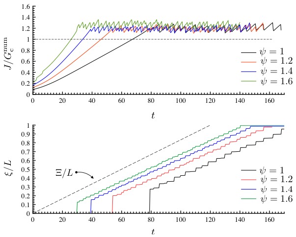
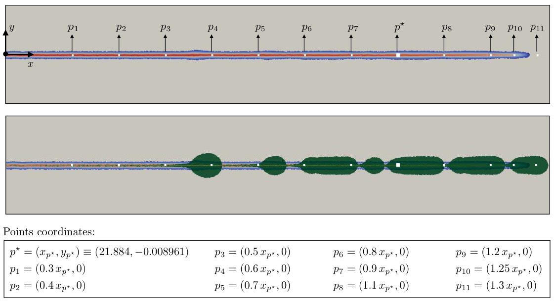
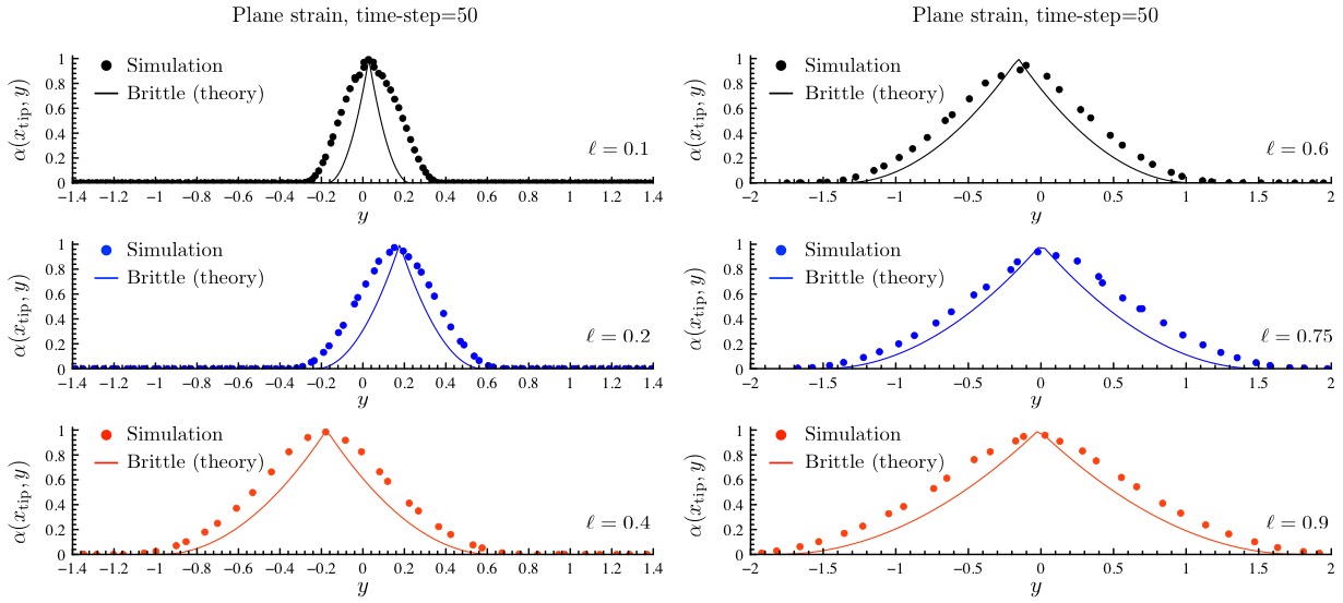
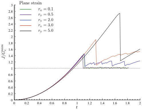
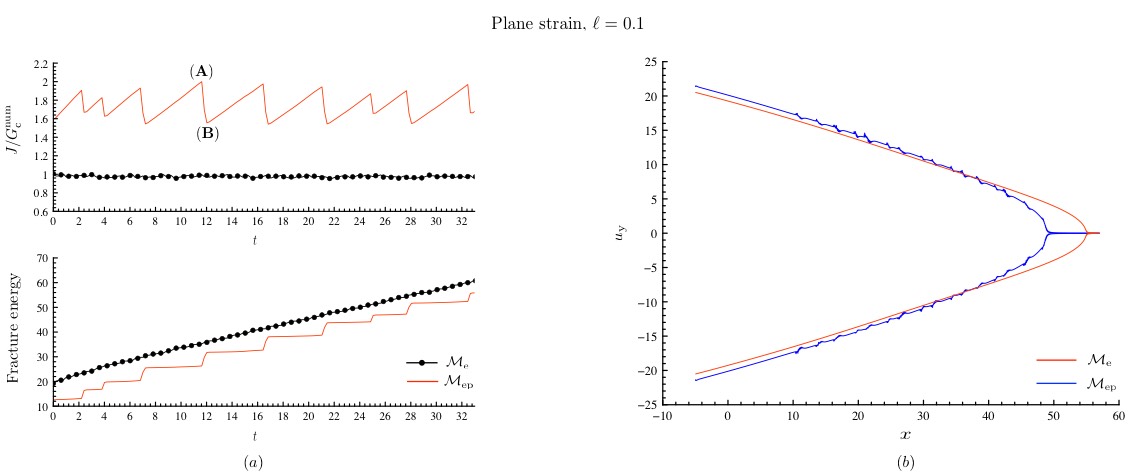
Figure 14 shows the typical result for a ductile material in plane strain conditions and contrasts it with that of an elastic material. Initially, the energy release rate of the applied boundary condition is too small to drive the crack and it remains stationary. As time passes and the center of the applied macroscopic crack tip moves to the right, the energy release rate increases with no crack growth. A plastic zone consisting of two lobes appear at the crack-tip. At some point, the energy release rate reaches a critical value and the crack jumps in the elastic-plastic material, and this is accompanied by a drop in the energy release rate. The crack is arrested and the plastic zone grows and energy release rate increases with continued loading till it reaches a critical value. The crack then jumps and the cycle repeats. In other words, crack propagation in the elastic-plastic material follows a jerky or intermittent pattern of alternating arrest and jump despite the fact that the macroscopic driving is steady. A consequence of the jerky motion is that the plastic zone is non-uniform and provides a record of the locations where the crack is arrested. This results in a crack surface that is rough as is clear from the crack opening profile shown in Figure 14(b). It has been verified (see Supplementary material) that these results do not depend on the length of the pre-crack () and the scaling factor of the applied boundary condition.
This jerky evolution of the ductile material is different from the relatively steady evolution that is observed in the purely elastic (brittle) case also shown in Figure 14. Further, the effective toughness (i.e., the peak applied energy release rate) of the elastic-plastic (ductile) material is significantly higher than that of the elastic (brittle) material.
It has long been recognized that the ductile material would be tougher than the brittle material due to the extra dissipation of plasticity (see (Hutchinson, 1989) and references there). However, the observation of jerky motion appears new, and a departure from the arguments of (Rice, 1968; Rice and Sorensen, 1978; Hutchinson, 1989). They compare a pinned crack (in an infinite medium loaded at infinity) and one that is steadily propagating, and show that the former has a smaller incremental energy release rate than that of the latter. They argue if the pinned crack were to start propagating continuously with time, the energy release rate would increase monotonically thereby ensuring the incremental stability of this solution. The results here show that there is another solution to the problem – one where the crack jumps. The setting of rate independent, perfect plasticity means that one can have multiple solutions. Further incremental stability of a solution involving crack propagating continuously with time does not imply stability against a solution involving crack jumps.
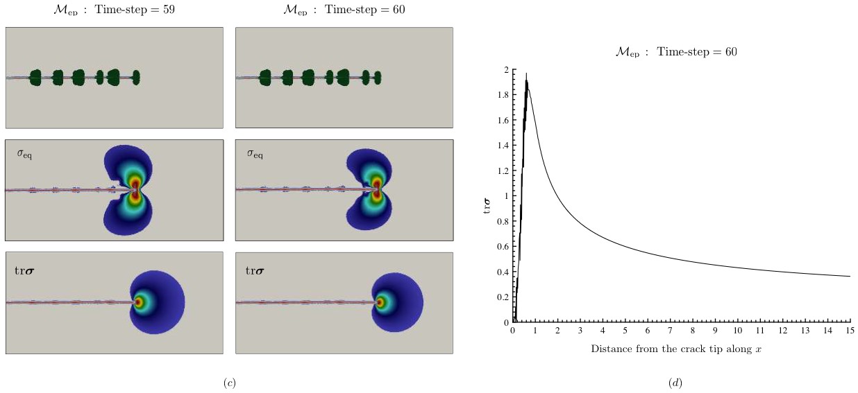
The source of the intermittent crack growth is evident by examining the hydrostatic stress, also shown in Figure 14 (c,d). This is positive and reaches its peak ahead of the crack tip. This would suggest that a daughter crack would nucleate ahead of the crack tip and then propagate backwards to join the main crack. This happens instantaneously in the current rate-independent, perfectly plastic model and manifests itself as a crack jump. This understanding is consistent with the recent work cited in (Benzerga and Leblond, 2010) (also (Benzerga et al., 2004; Pineau et al., 2016)) who argue that voids would nucleate ahead of the crack tip and eventually coalesce. Further, the experimental observations of (Kobayashi and Giovanola, 1989) clearly shows the appearance of a daughter crack ahead of the main crack followed by coalescence albeit in a dynamical setting. Finally, the jerky motion results in a rough or dimpled crack surface and this is well established in fractography (Hull, 1999).
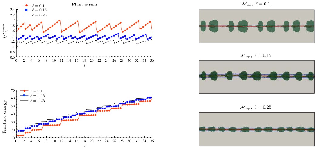
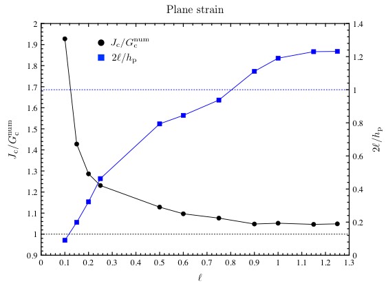

The role of regularization parameter is studied in Figure 15 holding the ratio and the yield strength constant. This keeps the numerical toughness in elastic materials the same as is varied. However, notice that increasing decreases the nucleation stress (see Eq. (8)) which in turn makes the material less ductile by decreasing (see Eq. (9)). Thus, the effective toughness of elastic-plastic materials (peak value of ) and the thickness of the plastic process zone decrease as shown in the figure.
Finally, the mesh size influences the crack propagation in two ways as shown in Figure 16. Recall from (7) that the numerical toughness in the purely brittle case depends on . This is normalized in the figure as is clear from the purely elastic case. Still the effective toughness given by the peak energy release rate is affected by . This suggests that the discretization affects the effective toughness differently in the ductile and brittle cases. However, the stress and distribution as well as the jerky propagation of the cracks is not affected by the discretization.
Plane stress.
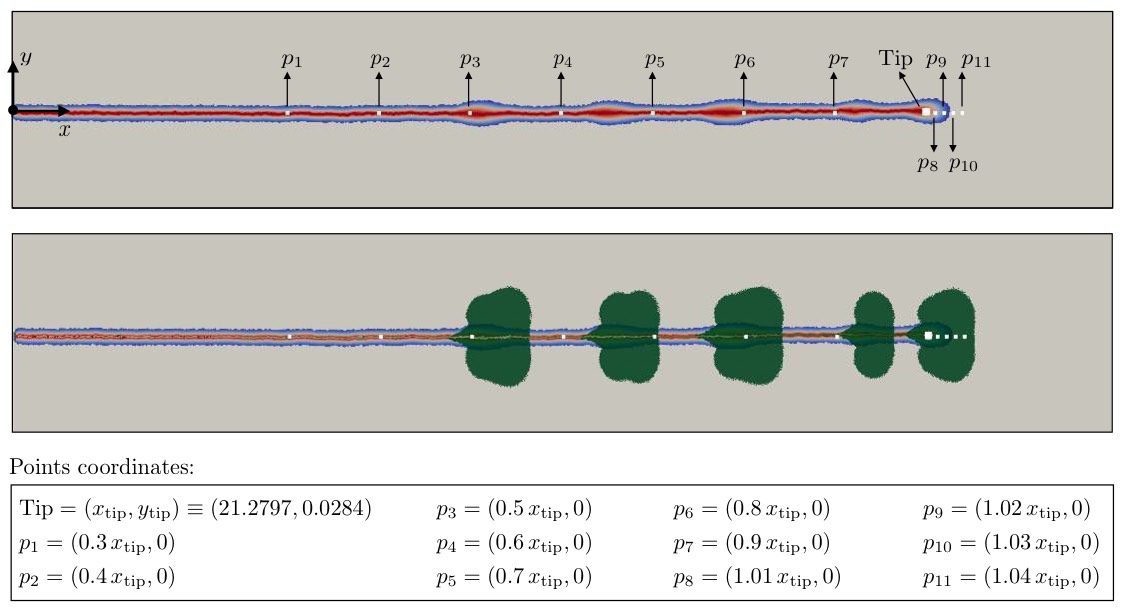
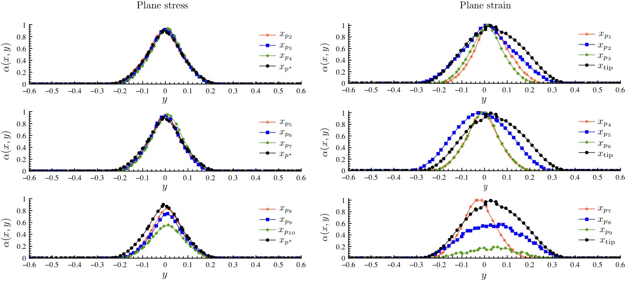
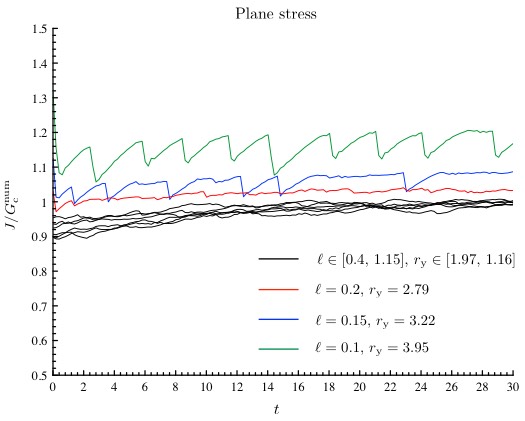
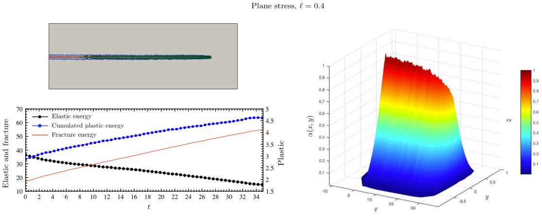
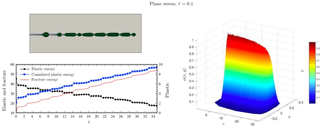
Figure 17 collects the results for a variety of elastic-plastic materials with varying regularization length but constant von Mises strength (so the ductility ratio changes) and numerical toughness (i.e., is changed to keep the ratio / constant). Figure 18 shows more details for a representative material with small ductility ratio and Figure 19 for a representative material with large ductility ratio.
For small values of , a region of intense plastic deformation and fracture process develops at the pre-crack tip and begins to grow steadily when the energy-release rate reaches a critical value, just below the toughness . Apart from numerical oscillations, the measured -integral remains essentially constant as this zone grows. The fracture field in this region is close to but not exactly equal to the one; so the fracture process is not complete. A different scenario arises when increases: the plastic process zone becomes larger and starts interacting with fracture in a more complicated and jerky manner resembling crack growth in the plane strain conditions. However, again, the fracture process is not complete.
Summary.
Crack propagation depends strongly on the ratio between the nucleation stress and the yield strength. In the quasi-brittle situation where this ratio is small (), the crack propagation is similar to that in purely elastic materials – it is steady and the toughness is close to the prescribed value . The ductile situation is different. In plane strain, crack propagation proceeds in a jerky fashion with a plastic zone pinning the crack till the imposed driving force reaches a high value when a crack advances with a finite jump, gets re-pinned and the cycle repeats. This mechanism is a result of the fact that the stress triaxiality is highest ahead of a pinned crack. The effective toughness is higher than the prescribed value , and increases with ductility ratio . The plastic deformation is not uniform and the fracture surface is rough. In plane stress, failure is accompanied by intense plastic deformation ahead of the crack tip and the fracture process is not complete.
6 Conclusion
In this paper, crack nucleation and propagation in elastic - perfectly plastic materials has been investigated in a phase-field or variational fracture field setting. The model proposed by (Alessi et al., 2014, 2015) has been implemented numerically and used to study crack nucleation at a sharp notch, crack initiation in a notched specimen and crack propagation under a steady driving. In a quasi-brittle setting (characterized by the ratio of the critical stress for crack nucleation to yield stress being smaller than unity), plastic deformation is limited to a small region near the crack tip and the nucleation, propagation and toughness is similar to that of brittle (purely elastic) materials. This is consistent with the notion of small scale yielding (Hutchinson, 1989).
The behavior is different in the ductile setting when the critical stress for nucleation exceeds the yield strength. In plane strain, there are two symmetric lobes of plastic deformation at the crack (notch) top. This pins the crack and one needs a very large driving force for the crack to un-pin (nucleate) the crack. When it does, the crack jumps ahead by a finite length. There is plastic deformation at the new crack tip and the cycle repeats. Consequently, the effective toughness of the material is higher, the crack propagation is intermittent or jerky and the fracture surface is rough. The source of the crack jump appears to be the fact the hydrostatic tension is high ahead of the crack tip. So, one expects voids to nucleate ahead of the pinned crack tip and then coalesce with the main crack. This appears instantaneous in our rate-independent, perfectly plastic setting. In plane stress, failure proceeds by intense plastic deformation ahead of the crack. The fracture process is not complete.
Acknowledgments
We have greatly benefited from many discussions with G. “Ravi” Ravichandran, Katherine Faber, Amine Benzerga and Alan Needleman. SB, BB, and KB acknowledge the financial support of the U.S. National Science Foundation (Grant No. DMS-1535083 and 1535076) under the Designing Materials to Revolutionize and Engineer our Future (DMREF) Program. Some numerical experiments were performed using resources of the Extreme Science and Engineering Discovery Environment (XSEDE), which is supported by National Science Foundation grant number OCI-1053575 under the Resource Allocation TG-DMS060014 and others at the Caltech high performance cluster supported in part by the Moore Foundation.
References
- Alessi et al. (2014) Roberto Alessi, Jean-Jacques Marigo, and Stefano Vidoli. Gradient damage models coupled with plasticity and nucleation of cohesive cracks. Archive for Rational Mechanics and Analysis, 214(2):575–615, 2014.
- Alessi et al. (2015) Roberto Alessi, Jean-Jacques Marigo, and Stefano Vidoli. Gradient damage models coupled with plasticity: variational formulation and main properties. Mechanics of Materials, 80:351–367, 2015.
- Ambati et al. (2015) Marreddy Ambati, Tymofiy Gerasimov, and Laura De Lorenzis. Phase-field modeling of ductile fracture. Computational Mechanics, 55(5):1017–1040, 2015.
- Ambrosio and Tortorelli (1990) Luigi Ambrosio and Vincenzo Maria Tortorelli. Approximation of functional depending on jumps by elliptic functional via t-convergence. Communications on Pure and Applied Mathematics, 43(8):999–1036, dec 1990. ISSN 00103640. doi: 10.1002/cpa.3160430805. URL http://doi.wiley.com/10.1002/cpa.3160430805.
- Balay et al. (2013a) S. Balay, S. Abhyankar, M. Adams, J. Brown, P. Brune, K. Buschelman, L. D. Dalcin, V. Eijkhout, W. Gropp, D. Kaushik, M. Knepley, D. May, L. Curfman McInnes, T. Munson, K. Rupp, P. Sanan, B. Smith, S. Zampini, H. Zhang, and H. Zhang. PETSc Users Manual Revision 3.4. Technical report, Argonne National Laboratory (ANL), Argonne, IL (United States), sep 2013a.
- Balay et al. (2013b) S. Balay, J. Brown, K. Buschelman, W.D. Gropp, D. Kaushik, M. Knepley, L.C. McInnes, B. Smith, and H. Zhang. PETSc/Tao: Home Page, 2013b. URL https://www.mcs.anl.gov/petsc/.
- Balay et al. (1997) Satish Balay, William D. Gropp, Lois Curfman McInnes, and Barry F. Smith. Efficient Management of Parallelism in Object-Oriented Numerical Software Libraries. In Modern Software Tools for Scientific Computing, pages 163–202. Birkhäuser Boston, Boston, MA, 1997. doi: 10.1007/978-1-4612-1986-6˙8. URL http://link.springer.com/10.1007/978-1-4612-1986-6{_}8.
- Benzerga and Leblond (2010) A Amine Benzerga and Jean-Baptiste Leblond. Ductile fracture by void growth to coalescence. In Advances in applied mechanics, volume 44, pages 169–305. Elsevier, 2010.
- Benzerga et al. (2004) AA Benzerga, Jacques Besson, and André Pineau. Anisotropic ductile fracture: Part i: experiments. Acta Materialia, 52(15):4623–4638, 2004.
- Benzerga et al. (2016) Ahmed Amine Benzerga, Jean-Baptiste Leblond, Alan Needleman, and Viggo Tvergaard. Ductile failure modeling. International Journal of Fracture, 201(1):29–80, 2016.
- Beremin (1981) FM Beremin. Cavity formation from inclusions in ductile fracture of a508 steel. Metallurgical Transactions A, 12(5):723–731, 1981.
- Bourdin et al. (2000) B. Bourdin, G.A. Francfort, and J-J. Marigo. Numerical experiments in revisited brittle fracture. Journal of the Mechanics and Physics of Solids, 48(4):797–826, apr 2000. ISSN 0022-5096. doi: 10.1016/S0022-5096(99)00028-9. URL https://www.sciencedirect.com/science/article/pii/S0022509699000289.
- Bourdin et al. (2008) Blaise Bourdin, Gilles A. Francfort, and Jean-Jacques Marigo. The Variational Approach to Fracture. Journal of Elasticity, 91(1-3):5–148, apr 2008. ISSN 0374-3535. doi: 10.1007/s10659-007-9107-3.
- Bourdin et al. (2014) Blaise Bourdin, Jean-Jacques Marigo, Corrado Maurini, and Paul Sicsic. Morphogenesis and propagation of complex cracks induced by thermal shocks. Physical review letters, 112(1):014301, 2014.
- Cherepanov (1967) GP Cherepanov. Crack propagation in a continuum. Prikl. Mat. Mekh, 31(3):476–488, 1967.
- de Borst et al. (1999) René de Borst, Jerzy Pamin, and Marc GD Geers. On coupled gradient-dependent plasticity and damage theories with a view to localization analysis. European Journal of Mechanics-A/Solids, 18(6):939–962, 1999.
- DESCATHA et al. (1981) Y DESCATHA, P LEDERMANN, JC DEVAUX, F MUDRY, A PINEAU, and JC LAUTRIDOU. Experimental and numerical study of the different stages in ductile rupture- application to crack initiation and stable crack growth. Three-dimensional constitutive relations and ductile fracture.(A 83-18477 06-39) Amsterdam, North-Holland Publishing Co., 1981,, pages 185–205, 1981.
- Francfort and Marigo (1998) G.A. Francfort and J.-J. Marigo. Revisiting brittle fracture as an energy minimization problem. Journal of the Mechanics and Physics of Solids, 46(8):1319–1342, aug 1998. ISSN 0022-5096. doi: 10.1016/S0022-5096(98)00034-9. URL https://www.sciencedirect.com/science/article/pii/S0022509698000349.
- Gurson (1977) Arthur L Gurson. Continuum theory of ductile rupture by void nucleation and growth: Part i—yield criteria and flow rules for porous ductile media. Journal of engineering materials and technology, 99(1):2–15, 1977.
- Hossain et al. (2014) M. Z. Hossain, C. J. Hsueh, B. Bourdin, and K. Bhattacharya. Effective toughness of heterogeneous media. Journal of the Mechanics and Physics of Solids, 71(1):15–32, 2014. ISSN 00225096. doi: 10.1016/j.jmps.2014.06.002. URL http://dx.doi.org/10.1016/j.jmps.2014.06.002.
- Hsueh et al. (2018) CJ Hsueh, L Avellar, B Bourdin, G Ravichandran, and K Bhattacharya. Stress fluctuation, crack renucleation and toughening in layered materials. Journal of the Mechanics and Physics of Solids, 2018.
- Hull (1999) Derek Hull. Fractography: observing, measuring and interpreting fracture surface topography. Cambridge University Press, 1999.
- Hutchinson (1989) John W Hutchinson. A course on nonlinear fracture mechanics. Department of Solid Mechanics, Techn. University of Denmark, 1989.
- Klinsmann et al. (2015) Markus Klinsmann, Daniele Rosato, Marc Kamlah, and Robert M McMeeking. An assessment of the phase field formulation for crack growth. Computer Methods in Applied Mechanics and Engineering, 294:313–330, 2015.
- Kobayashi and Giovanola (1989) T Kobayashi and JH Giovanola. Crack opening profile observations for dynamic cleavage crack propagation and arrest. Journal of the Mechanics and Physics of Solids, 37(6):759–777, 1989.
- Leguillon and Sanchez-Palencia (1987) Dominique Leguillon and Enrique Sanchez-Palencia. Computation of singular solutions in elliptic problems and elasticity. John Wiley & Sons, Inc., 1987.
- Miehe et al. (2015) Christian Miehe, M Hofacker, L-M Schänzel, and Fadi Aldakheel. Phase field modeling of fracture in multi-physics problems. part ii. coupled brittle-to-ductile failure criteria and crack propagation in thermo-elastic–plastic solids. Computer Methods in Applied Mechanics and Engineering, 294:486–522, 2015.
- Miehe et al. (2016) Christian Miehe, Fadi Aldakheel, and Arun Raina. Phase field modeling of ductile fracture at finite strains: A variational gradient-extended plasticity-damage theory. International Journal of Plasticity, 84:1–32, 2016.
- Nedjar (2001) B Nedjar. Elastoplastic-damage modelling including the gradient of damage: formulation and computational aspects. International Journal of Solids and Structures, 38(30-31):5421–5451, 2001.
- Needleman and Tvergaard (1987) Al Needleman and V Tvergaard. An analysis of ductile rupture modes at a crack tip. Journal of the Mechanics and Physics of Solids, 35(2):151–183, 1987.
- Pham et al. (2017) KH Pham, K Ravi-Chandar, and CM Landis. Experimental validation of a phase-field model for fracture. International Journal of Fracture, 205(1):83–101, 2017.
- Pham et al. (2011) Kim Pham, Hanen Amor, Jean-Jacques Marigo, and Corrado Maurini. Gradient damage models and their use to approximate brittle fracture. International Journal of Damage Mechanics, 20(4):618–652, 2011.
- Pineau et al. (2016) André Pineau, Amine A Benzerga, and Thomas Pardoen. Failure of metals i: Brittle and ductile fracture. Acta Materialia, 107:424–483, 2016.
- Reusch et al. (2003) Frederick Reusch, Bob Svendsen, and Dietmar Klingbeil. Local and non-local gurson-based ductile damage and failure modelling at large deformation. European Journal of Mechanics-A/Solids, 22(6):779–792, 2003.
- Rice (1968) James R Rice. Mathematical Analysis in the Mechanics of Fracture. Technical report, 1968. URL http://esag.harvard.edu/rice/018{_}Rice{_}MathAnalMechFract{_}68.pdf.
- Rice and Sorensen (1978) JR Rice and E Po Sorensen. Continuing crack-tip deformation and fracture for plane-strain crack growth in elastic-plastic solids. Journal of the Mechanics and Physics of Solids, 26(3):163–186, 1978.
- Tanne (2017) Erwan Tanne. Variational phase-field models from brittle to ductile fracture: nucleation and propagation. PhD thesis, Paris Saclay, 2017.
- Tanné et al. (2018) Erwan Tanné, Tianyi Li, Blaise Bourdin, J-J Marigo, and Corrado Maurini. Crack nucleation in variational phase-field models of brittle fracture. Journal of the Mechanics and Physics of Solids, 110:80–99, 2018.
- Zehnder (2012) Alan T. Zehnder. Fracture Mechanics, volume 62 of Lecture Notes in Applied and Computational Mechanics. Springer Netherlands, Dordrecht, 2012. ISBN 978-94-007-2594-2. doi: 10.1007/978-94-007-2595-9. URL http://link.springer.com/10.1007/978-94-007-2595-9.
- Zhang et al. (2017) Xue Zhang, Chet Vignes, Scott Sloan, and Daichao Sheng. Numerical evaluation of the phase-field model for brittle fracture with emphasis on the length scale. JComputational Mechanics, 59:737–752, 2017.
Supplementary material