Bath engineering of a fluorescing artificial atom with a photonic crystal
Abstract
We demonstrate how the dissipative interaction between a superconducting qubit and a microwave photonic crystal can be used for quantum bath engineering. The photonic crystal is created with a step-impedance transmission line which suppresses and enhances the quantum spectral density of states, influencing decay transitions of a transmon circuit. The qubit interacts with the transmission line indirectly via dispersive coupling to a cavity. We characterize the photonic crystal density of states from both the unitary and dissipative dynamics of the qubit. When the qubit is driven, it dissipates into the frequency dependent density of states of the photonic crystal. Our result is the deterministic preparation of qubit superposition states as the steady-state of coherent driving and dissipation near by the photonic crystal band edge, which we characterize with quantum state tomography. Our results highlight how the multimode environment from the photonic crystal forms a resource for quantum control.
In experimental quantum information processing, there exists a tradeoff between control of quantum states and dissipation. However, dissipation can in fact be a resource for quantum control. An early example of dissipation engineering is laser cooling of atoms, where drive in combination with atomic decay is used to initialize atomic states Wineland and Itano (1979). Such techniques have been extended to cool mechanical objects through cavity dissipation Aspelmeyer et al. (2014) and for control of quantum circuits Wilson et al. (2007); Kapit (2017). Dissipation engineering with quantum circuits has been demonstrated for a variety of applications including state reset Geerlings et al. (2013); Boutin et al. (2017); Wong et al. (2019) and the creation of entangled states Aron et al. (2014, 2016); Reiter et al. (2013); Shankar et al. (2013); Lin et al. (2013); Kimchi-Schwartz et al. (2016). More generally, these are examples of quantum bath engineering, where decay is deliberately used as a means for quantum state preparation Poyatos et al. (1996); Carvalho et al. (2001); Verstraete et al. (2009); Murch et al. (2012); Lu et al. (2017); Leghtas et al. (2015); Hacohen-Gourgy et al. (2015); Liu and Houck (2017); Kapit (2017). In another research arena, there is growing interest in the interaction of quantum systems with multimode environments Sundaresan et al. (2015); Puertas Martinez et al. ; Kuzmin et al. such as photonic crystals Cerbu et al. ; Liu and Houck (2017); Sundaresan et al. ; Mirhosseini et al. (2018) where impurity models Le Hur (2012); Goldstein et al. (2013), ultrastrong coupling Forn-Díaz et al. (2016); Yoshihara et al. (2017); Puertas Martinez et al. , and driven-dissipative phase transitions Houck et al. (2012); Raftery et al. (2014); Fitzpatrick et al. (2017) can play a leading role. In this letter, we show how the dissipation of a quantum circuit into the multiple electromagnetic modes that form the bands and gaps of a photonic crystal can be used to prepare non-trivial quantum states of the circuit through bath engineering. Our bath engineering protocol results in deterministic decay to superposition states of the two lowest energy levels of the superconducting circuit, which we investigate with full quantum state tomography. We find close agreement between experimentally measured steady-states and the predicted Lindblad evolution for a range of coherent drive parameters. Our results add to the growing tool box of dissipation engineering techniques for quantum control of superconducting circuits.
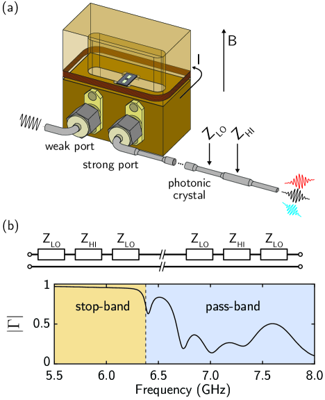
Our experiment comprises a one-dimensional photonic crystal coupled to a flux tunable transmon-type superconducting artificial atom Koch et al. (2007); Paik et al. (2011) housed inside a waveguide cavity () (Fig. 1a) at milliKelvin temperatures. The transmon circuit has an anharmonic energy potential, allowing the two lowest energy levels to be addressed as a qubit transition. Outside the cavity, the photonic crystal is a coaxial transmission line with a spatially modulated impedance SM , which connects the strongly coupled antenna port of the waveguide cavity to the electromagnetic environment of the microwave readout chain. The photonic crystal consists of 25 impedance steps (, ) along the coaxial line, resulting in the opening of a bandgap (Fig. 1b) Joannopoulos et al. (2008); Mirhosseini et al. (2018). Because the transmon is dispersively coupled to the cavity, the qubit transition interacts perturbatively with the photonic crystal density of states. The decay of the transmon qubit into the photonic crystal is strongly influenced by the presence of the photonic bandgap Bykov (1972); Yablonovitch (1987), since the rate of spontaneous emission is proportional to the local density of states at the transition frequency of an emitter Dirac (1927); Purcell (1946).
Furthermore, the qubit-cavity dispersive coupling enables single shot readout using the Jaynes-Cummings nonlinearity technique at the bare cavity resonance Reed et al. (2010). We use this to conduct full quantum state tomography of the qubit and characterize the bath engineering decay process. Readout is performed by driving the strongly coupled port of the cavity through the photonic crystal. At a critical drive power the threshold behavior of this readout technique is observed in the phase shift of the reflection tone, achieving a readout fidelity of , amenable to qubit state tomography. To account for this unideal readout fidelity, we calibrate tomography measurements by preparing eigenstates of , , and , measuring their expectation values, and rescaling experimental expectation values accordingly.
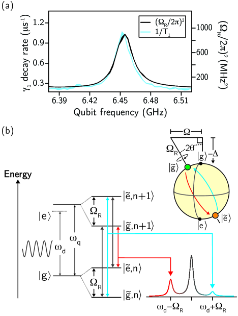
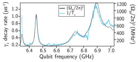
Before implementing the bath engineering protocol, we characterize the interaction of the qubit and the photonic crystal across a range qubit transition frequencies. First, we determine the frequency dependence of the local density of states by flux biasing the qubit transition to a specific frequency and performing standard decay measurements (Fig. 2a). Variation of the qubit decay rate is attributed to changes in the local density of states according to,
| (1) |
which is decay rate of the qubit dispersively coupled to a single cavity mode Schuster (2007); Houck et al. (2008), where is the cavity linewidth, is the qubit-cavity coupling rate, is the qubit-cavity detuning, is the local density of states at the qubit frequency, and is the qubit decay rate into other dissipation channels. As mentioned, the cavity provides a filtered coupling to the strongly varying density of states provided by the photonic crystal.
To verify the measured qubit decay is in fact influenced by the local density of states of the photonic crystal, we additionally investigate variations of the coupling rate between the qubit and its photonic crystal environment. At each flux bias, we perform resonant Rabi frequency measurements from a drive of a fixed amplitude applied through the photonic crystal (Fig. 2a). Similar to qubit decay, variation of the Rabi frequency is attributed to qubit absorption and emission rates, due to the qubit coupling to the continuum by way of the photonic crystal. By comparing the decay rate and the Rabi frequency squared , we find agreement in the proportional changes of decay and coupling rates and establish that the photonic crystal forms the spectral density of states for qubit emission and absorption, since both the qubit decay rate and the squared Rabi frequency both depend proportionally on the local density of states. From this, we attribute changes of the qubit decay rate to the large variation of the local density of states between the stop-band and pass-band of the photonic crystal.
We now apply a coherent drive on the qubit through the weakly coupled cavity port to implement our bath engineering protocol. The coherent drive, along with the photonic crystal spectral density of states, determines the steady-state of the bath engineering process by inducing specific decay transitions of the qubit Yan et al. (2008). We solve for this steady-state by considering the system dynamics under drive and decay. The time-evolution of our bath engineering process is simply modeled as a two level emitter under coherent drive, since the qubit interacts only weakly with the dissipative photonic states SM . The open quantum system dynamics of a transmon qubit driven from a coherent tone at frequency at resonant Rabi frequency and detuning , can be described by the Lindblad master equation Lindblad (1976), assuming timescales of photonic state relaxation are much shorter than that of the qubit Scala et al. (2007); Gambetta et al. (2008); Boissonneault et al. (2009); Aron et al. (2016); Liu and Houck (2017),
| (2) |
where is the reduced density operator for the qubit dressed by the light-field in the rotating frame of the drive. The operators are Pauli raising and lowering operators in the qubit dressed basis and is the Hamiltonian of the qubit with , and the generalized Rabi frequency . The dephasing rate in the dressed basis is and transitions between these eigenstates occur at rates , as captured by the dissipation superoperator . The dressed qubit energy eigenbasis formed by coherent driving at frequency , comprises superpositions of the bare qubit eigenstates as illustrated in Figure 2b,
where . After sufficiently long time evolution of Eq. Bath engineering of a fluorescing artificial atom with a photonic crystal, the qubit relaxes to a nonequilibrium effective ground state: a steady-state of the driven-dissipative dynamics Raftery et al. (2014). Importantly, a superposition state results from an asymmetry in transition rates between the dressed states, due to the frequency dependence of the photonic density of states.
We now discuss the role of the photonic crystal for decay to a specific qubit steady-state. Without drive, the qubit decays to its ground state according to Eq. (Bath engineering of a fluorescing artificial atom with a photonic crystal) which reduces to , where is given by Eq. (1) and the qubit emits a photon at the qubit transition frequency . A coherent drive on the qubit introduces a new energy scale , allowing the qubit to couple to the electromagnetic field at frequencies and . For a resonant drive, the latter frequencies correspond to transitions given by the operators,
in the limit of strong excitation where . If the spectral density of states of the electromagnetic field at are equal, the rates for the transitions are equally favored resulting in a mixed state for the qubit. However, when the photonic crystal results in a colored density of states, the rates associated with can be unequal, favoring decay to either the or state.
Emission of the driven system creates field correlations that manifest as the Mollow triplet spectrum (Fig. 2b) Baur et al. (2009); Toyli et al. (2016); Mollow (1969). The asymetry in the rates leads to an asymmetry in the Mollow triplet. In the ideal scenario for bath engineering, there is a thoroughly dissimilar local density of states at frequencies , resulting in a single sideband Mollow triplet and deterministic decay to one of the two dressed states.
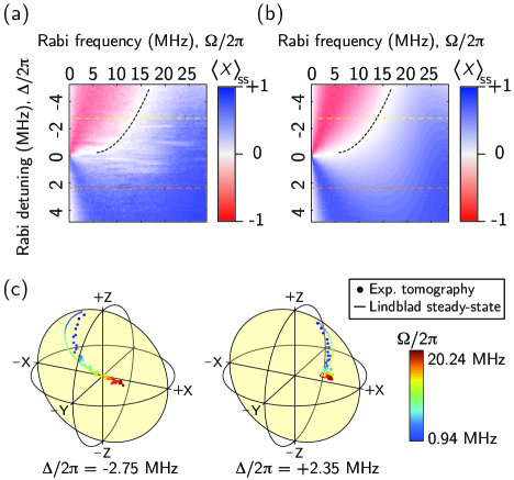
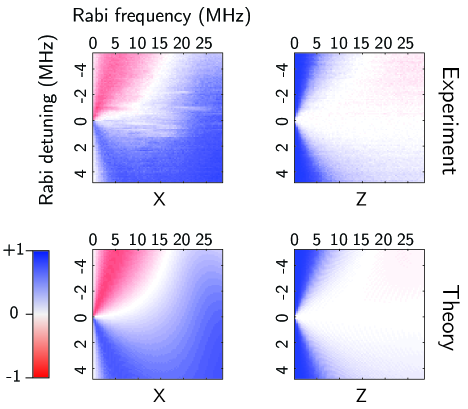
We demonstrate bath engineering decay to a dressed state by flux tuning the qubit to where the local density of states varies dramatically, as shown in Figure 2a. In Figure 3a, we display the measured steady-state qubit coherence , where is the tomographically reconstructed qubit state after of driving and is the Pauli operator in the undressed basis. Here, we observe two signatures of the photonic crystal density of states. First, we find the steady-states mapped in Figure 3a,b contain a feature of zero coherence (dashed-line) for certain coherent drive parameters of detuning and amplitude. This occurs when the two terms in Eq. (2) cancel due to the dependence of both and on and . A maximally mixed steady-state is a consequence of equal transition rates between dressed states. Physically, the overlap of the dressed states with the globally favored ground state competes with the dressed state favored by . In a picture of detailed balance for the rate of transitions between dressed states, this occurs for drive parameters satisfying the relation
| (3) |
which was used to calculate the dashed lines of Figure 3a,b. A second signature of the photonic crystal is observed by the increase of the steady-state coherence for a resonant drive. Although this coherence is limited in our experiment by decay to other dissipation channels, we find an overall increase of steady-state coherence because the dressed state transition rates become more asymmetric as the Mollow triplet spectrum widens in the presence of a colored local density of states. While small coherences can be created from a weak drive in resonance fluorescence Carmichael et al. (1987), the observation of coherence from a strong drive is a clear indicator of an asymmetry in the rates due to the density of state of the photonic crystal. Furthermore, we note that the asymmetric density of states of the readout cavity is negligible due to its large detuning from the qubit resonance .
Consequently, we find that the qubit is “cooled” to a chosen superposition state in the eigenbasis of the undriven qubit from a proper selection of a drive phase, frequency, and amplitude (Fig. 3), enabled by the asymmetric density of states of the photonic crystal. The theory colormap of Figure 3b was produced by solving for the steady-states of Eq. Bath engineering of a fluorescing artificial atom with a photonic crystal given the local density of states as inferred from measurements shown in Figure 2. This theory reproduces all qualitative features of the tomography results and has quantitative agreement when including additional pure dephasing of the qubit transition , consistent with typical limits of coherence for transmon qubits SM .
In conclusion, we have shown that the driven and dissipative dynamics of a transmon qubit weakly coupled to a photonic crystal can be used for quantum bath engineering, as we have verified with full state tomography. Our protocol robustly prepares a desired qubit superposition state, realized as an effective ground state of the driven-dissipative system. The colored density of states introduced from the photonic crystal is crucial for our method and highlights impedance engineering of the electromagnetic environment as a key aspect of bath engineering for circuit quantum electrodynamics. In future bath engineering implementations, the photonic density of states can be tailored by fabrication techniques with lumped element metamaterials Mirhosseini et al. (2018) and in situ tunability of coupling rates between photonic modes Lu et al. (2017); Collodo et al. . Additionally, quantum monitoring of dissipative photonic modes of the environment can further the scope of bath engineering protocols for non-unitary heralding of quantum states and quantum control by dynamical feedback Sayrin et al. (2011); Vijay et al. (2012); Shankar et al. (2013); Ristè et al. (2013); de Lange et al. (2014); Roch et al. (2014); Naghiloo et al. (2016); Campagne-Ibarcq et al. (2016).
Acknowledgements.
We thank A. A. Clerk, P. Bertet, I. Martin, and J. Monroe for helpful conversations, and we appreciate J. R. Lane and J. Pollanen for preliminary experimental contributions. We acknowledge research support the NSF (Grant PHY-1607156) and from ONR (Grant 12114811). This research used facilities at the Institute of Materials Science and Engineering at Washington University. D. T. acknowledges support from the Rigetti Computing Postdoctoral Fellowship.Appendix A: Photonic crystal fabrication and characterization
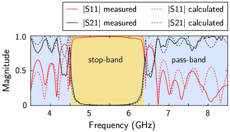
The photonic crystal was hand fabricated from a semi-rigid transmission line (Micro Coax UT-085C-TP-LL). Since the TEM propogation mode geometry determines the characteristic impedance of the transmission line, a periodic modulation of the transmission line geometry along the line forms a finite length one-dimensional photonic crystal. Transmission line sections were mechanicaly deformed by crushing the coax, creating lengths of characteristic impedance , as found consistent with Ansys HFSS simulation.
We modeled the photonic crystal in AWR Microwave Office as a Chebychev Type I bandstop filter. Given prior knowledge that squashed SMA sections have characteristic impedance and the dielectric constant of PTFE (), we optimized for an experimentally convenient frequency for the upper band edge, resulting the the parameters given in Table I. The lengths of the 25 impedance sections were used to fabrication the photonic crystal. In Figure 4, we present measured and calculated scattering parameters for the photonic crystal. The scattering parameters were calculated from cascaded transfer matrices of transmission line sections of length in Table I and with a minor adjustment to the transmission line dielectric constant ().
| Step # | (mm) | Step # | (mm) | Step # | (mm) | Step # | (mm) | Step # | (mm) | |||||
| 1 | 30 | 9.1 | 6 | 50 | 9.4 | 11 | 30 | 10.2 | 16 | 50 | 9.7 | 21 | 30 | 9.7 |
| 2 | 50 | 9.4 | 7 | 30 | 9.9 | 12 | 50 | 9.7 | 17 | 30 | 10.2 | 22 | 50 | 10.9 |
| 3 | 30 | 9.1 | 8 | 50 | 9.7 | 13 | 30 | 10.2 | 18 | 50 | 9.7 | 23 | 30 | 9.1 |
| 4 | 50 | 10.7 | 9 | 30 | 10.2 | 14 | 50 | 9.7 | 19 | 30 | 9.9 | 24 | 50 | 9.4 |
| 5 | 30 | 9.7 | 10 | 50 | 9.7 | 15 | 30 | 10.2 | 20 | 50 | 9.4 | 25 | 30 | 9.1 |
Appendix B: Additional data of the photonic crystal characterization
The photonic crystal density of states was characterized from both unitary and dissipative dynamics of the qubit. By the same methods as described for Figure 2 of the main text, we show the qubit decay rate is determined by the environment of the photonic crystal density of states.
Appendix C: Steady-state simulation
A qubit with an energy eigenbasis is described by the Hamiltonian in the lab frame. When the qubit is dipole coupled to a coherent drive of frequency , we transform the lab frame Hamiltonian of the driven qubit into the rotating frame of the drive with the unitary operator as . The rotating frame Hamiltonian is
| (4) |
upon neglecting rapidly oscillating terms and where is the qubit-drive detuning and is the frequency of Rabi oscillations in the case of a resonant drive. We diagonalize Eq. 4 to find the dressed energy eigenstates,
where and . We define the energy eigenstates such that when the qubit is driven far-red detuned and when the qubit is driven far-blue detuned. We rewrite the Hamiltonian in the dressed state basis as,
where and .
We wish to consider the interaction picture of the driven qubit weakly coupled to a dissipative environment, such that we can treat the interaction as a perturbation. The driven qubit interacting with dissipative modes of the electromagnetic environment is described by the interaction Hamiltonian in the rotating frame of the drive,
where is the coupling strength to the electromagnetic mode of frequency with creation operator . Each term of the interaction Hamiltonian can be expressed in terms of dressed state operators as,
where we have simply made the substitution . We transform both the qubit and interaction Hamiltonian into the rotating frame of the dressed qubit described by the transformation where , giving the Hamiltonian
As we consider the time evolution of both the qubit and dissipative environment in the interaction picture, we assume the environment modes are sufficiently dissipative, such that we can make the Born approximation and trace out the environment degrees of freedom. We subsequently make the Markov approximation, and assume time evolution is coarse grained enough for the environment local density of states to determine jump rates of the open system dynamics. The time evolution for the reduced density matrix of the qubit is described by the Lindblad master equation,
where , , , and .
Numerical calculations were performed in the dressed state basis including unitary evolution from Rabi oscillations described by the master equation,
where the final term of the master equation captures an additional pure dephasing of rate in the lab frame of the qubit. The density matrix time evolution was numerically solved by recasting the Lindblad superoperator into a matrix which maps a vector representation of the density matrix to another vector. The qubit density matrix is expressed as the column vector, . We construct the Lindblad operator as a matrix in operator space by expressing left-operation () and right-operation () on the density matrix with tensor products. Matrices of left- and right- operation are
and,
Time evolution from an initial qubit state is calculated from the equation, , where we perform matrix exponentiation of by finding the matrix which diagonalizes the Lindblad matrix. After converting the density matrix vector into a matrix operator (), we then calculate expectation values in the lab frame rotating with the drive,
where the Pauli operators in terms of the dressed state basis are , , and .
Appendix D: Full state tomography
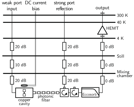
Appendix E: Experiment setup
References
- Wineland and Itano (1979) D. J. Wineland and W. M. Itano, “Laser Cooling of Atoms,” Phys. Rev. A 20, 1521–1540 (1979).
- Aspelmeyer et al. (2014) M. Aspelmeyer, T. J. Kippenberg, and F. Marquardt, “Cavity Optomechanics,” Rev. Mod. Phys. 86, 1391–1452 (2014).
- Kapit (2017) E. Kapit, “The Upside of Noise: Engineered Dissipation as a Resource in Superconducting Circuits,” Quantum Science and Technology 2, 033002 (2017).
- Wilson et al. (2007) C. M. Wilson, T. Duty, F. Persson, M. Sandberg, G. Johansson, and P. Delsing, “Coherence Times of Dressed States of a Superconducting Qubit under Extreme Driving,” Phys. Rev. Lett. 98, 257003 (2007).
- Geerlings et al. (2013) K. Geerlings, Z. Leghtas, I. M. Pop, S. Shankar, L. Frunzio, R. J. Schoelkopf, M. Mirrahimi, and M. H. Devoret, “Demonstrating a Driven Reset Protocol for a Superconducting Qubit,” Phys. Rev. Lett. 110, 120501 (2013).
- Boutin et al. (2017) S. Boutin, C. K. Andersen, J. Venkatraman, A. J. Ferris, and A. Blais, “Resonator Reset in Circuit QED by Optimal Control for Large Open Quantum Systems,” Phys. Rev. A 96, 042315 (2017).
- Wong et al. (2019) C. H. Wong, C. Wilen, R. McDermott, and M. G. Vavilov, “A Tunable Quantum Dissipator for Active Resonator Reset in Circuit QED,” Quantum Science and Technology 4, 025001 (2019).
- Aron et al. (2014) C. Aron, M. Kulkarni, and H. E. Türeci, “Steady-State Entanglement of Spatially Separated Qubits via Quantum Bath Engineering,” Phys. Rev. A 90, 062305 (2014).
- Aron et al. (2016) C. Aron, M. Kulkarni, and H. E. Türeci, “Photon-Mediated Interactions: A Scalable Tool to Create and Sustain Entangled States of atoms,” Phys. Rev. X 6, 011032 (2016).
- Reiter et al. (2013) F. Reiter, L. Tornberg, G. Johansson, and A. S. Sørensen, “Steady-State Entanglement of Two Superconducting Qubits Engineered by Dissipation,” Phys. Rev. A 88, 032317 (2013).
- Shankar et al. (2013) S. Shankar, M. Hatridge, Z. Leghtas, K. M. Sliwa, A. Narla, U. Vool, S. M. Girvin, L. Frunzio, M. Mirrahimi, and M. H. Devoret, “Autonomously Stabilized Entanglement Between Two Superconducting Quantum Bits,” Nature 504, 419 (2013).
- Lin et al. (2013) Y. Lin, J. P. Gaebler, F. Reiter, Ting R. Tan, R. Bowler, A. S. Sørensen, D. Leibfried, and D. J. Wineland, “Dissipative Production of a Maximally Entangled Steady State of Two Quantum Bits,” Nature 504, 415 (2013).
- Kimchi-Schwartz et al. (2016) M. E. Kimchi-Schwartz, L. Martin, E. Flurin, C. Aron, M. Kulkarni, H. E. Türeci, and I. Siddiqi, “Stabilizing Entanglement via Symmetry-Selective Bath Engineering in Superconducting Qubits,” Phys. Rev. Lett. 116, 240503 (2016).
- Poyatos et al. (1996) J. F. Poyatos, J. I. Cirac, and P. Zoller, “Quantum Reservoir Engineering with Laser Cooled Trapped Ions,” Phys. Rev. Lett. 77, 4728–4731 (1996).
- Carvalho et al. (2001) A. R. R. Carvalho, P. Milman, R. L. de Matos Filho, and L. Davidovich, “Decoherence, Pointer Engineering, and Quantum State Protection,” Phys. Rev. Lett. 86, 4988–4991 (2001).
- Verstraete et al. (2009) F. Verstraete, M. M. Wolf, and I. J. Cirac, “Quantum Computation and Quantum-State Engineering Driven by Dissipation,” Nature Physics 5, 633–636 (2009).
- Murch et al. (2012) K. W. Murch, U. Vool, D. Zhou, S. J. Weber, S. M. Girvin, and I. Siddiqi, “Cavity-Assisted Quantum Bath Engineering,” Phys. Rev. Lett. 109, 183602 (2012).
- Lu et al. (2017) Y. Lu, S. Chakram, N. Leung, N. Earnest, R. K. Naik, Z. Huang, P. Groszkowski, E. Kapit, J. Koch, and D. I. Schuster, “Universal Stabilization of a Parametrically Coupled Qubit,” Phys. Rev. Lett. 119, 150502 (2017).
- Leghtas et al. (2015) Z. Leghtas, S. Touzard, I. M. Pop, A. Kou, B. Vlastakis, A. Petrenko, K. M. Sliwa, A. Narla, S. Shankar, M. J. Hatridge, M. Reagor, L. Frunzio, R. J. Schoelkopf, M. Mirrahimi, and M. H. Devoret, “Confining the State of Light to a Quantum Manifold by Engineered Two-Photon Loss,” Science 347, 853–857 (2015).
- Hacohen-Gourgy et al. (2015) S. Hacohen-Gourgy, V. V. Ramasesh, C. De Grandi, I. Siddiqi, and S. M. Girvin, “Cooling and Autonomous Feedback in a Bose-Hubbard Chain with Attractive Interactions,” Phys. Rev. Lett. 115, 240501 (2015).
- Liu and Houck (2017) Y. Liu and A. A. Houck, “Quantum Electrodynamics Near a Photonic Bandgap,” Nature Physics 13, 48–52 (2017).
- Sundaresan et al. (2015) N. M. Sundaresan, Y. Liu, D. Sadri, L. J. Szócs, D. L. Underwood, M. Malekakhlagh, H. E. Türeci, and A. A. Houck, “Beyond Strong Coupling in a Multimode Cavity,” Phys. Rev. X 5, 021035 (2015).
- (23) J. Puertas Martinez, S. Leger, N. Gheeraert, R. Dassonneville, L. Planat, F. Foroughi, Y. Krupko, O. Buisson, C. Naud, W. Guichard, S. Florens, I. Snyman, and N. Roch, “A Tunable Josephson Platform to Explore Many-Body Quantum Optics in Circuit-QED,” arXiv:1802.00633 .
- (24) R. Kuzmin, N. Mehta, N. Grabon, R. Mencia, and V. E. Manucharyan, “Cooling a Two-level Emitter in Photonic-crystal Environments,” .
- (25) M. Cerbu, M. A. Macovei, and G. X. Li, “Superstrong Coupling in Circuit Quantum Electrodynamics,” Phys. Rev. A 89, 013837 (2014).
- (26) N. M. Sundaresan, R. Lundgren, G. Zhu, A. V. Gorshkov, and A. A. Houck, “Interacting Qubit-Photon Bound States with Superconducting Circuits,” arXiv:1801.10167 .
- Mirhosseini et al. (2018) M. Mirhosseini, Kim E., V. S. Ferreira, M. Kalaee, A. Sipahigil, A. J. Keller, and O. Painter, “Superconducting Metamaterials for Waveguide Quantum Electrodynamics,” Nature Communications 13, 48–52 (2018).
- Le Hur (2012) K. Le Hur, “Kondo Resonance of a Microwave Photon,” Phys. Rev. B 85, 140506(R) (2012).
- Goldstein et al. (2013) M. Goldstein, M. H. Devoret, M. Houzet, and L. I. Glazman, “Inelastic Microwave Photon Scattering Off a Quantum Impurity in a Josephson-Junction Array,” Phys. Rev. Lett. 110, 017002 (2013).
- Forn-Díaz et al. (2016) P. Forn-Díaz, J. J. García-Ripoll, B. Peropadre, J.-L. Orgiazzi, M. A. Yurtalan, R. Belyansky, C. M. Wilson, and A. Lupascu, “Ultrastrong Coupling of a Single Artificial Atom to an Electromagnetic Continuum in the Nonperturbative Regime,” Nature Physics 13, 39 (2016).
- Yoshihara et al. (2017) F. Yoshihara, T. Fuse, S. Ashhab, K. Kakuyanagi, S. Saito, and K. Semba, “Superconducting Qubit-Oscillator Circuit Beyond the Ultrastrong-Coupling Regime,” Nature Physics 13, 44–47 (2017).
- Houck et al. (2012) A. A. Houck, H. E. Türeci, and J. Koch, “On-Chip Quantum Simulation with Superconducting Circuits,” Nature Physics 8, 292–299 (2012).
- Raftery et al. (2014) J. Raftery, D. Sadri, S. Schmidt, H. E. Türeci, and A. A. Houck, “Observation of a Dissipation-Induced Classical to Quantum Transition,” Phys. Rev. X 4, 031043 (2014).
- Fitzpatrick et al. (2017) M. Fitzpatrick, N. M. Sundaresan, A. C. Y. Li, J. Koch, and A. A. Houck, “Observation of a Dissipative Phase Transition in a One-Dimensional Circuit QED Lattice,” Phys. Rev. X 7, 011016 (2017).
- Koch et al. (2007) J. Koch, T. M. Yu, J. Gambetta, A. A. Houck, D. I. Schuster, J. Majer, A. Blais, M. H. Devoret, S. M. Girvin, and R. J. Schoelkopf, “Charge-Insensitive Qubit Design Derived from the Cooper Pair Box,” Phys. Rev. A 76, 042319 (2007).
- Paik et al. (2011) H. Paik, D. I. Schuster, L. S. Bishop, G. Kirchmair, G. Catelani, A. P. Sears, B. R. Johnson, M. J. Reagor, L. Frunzio, L. I. Glazman, S. M. Girvin, M. H. Devoret, and R. J. Schoelkopf, “Observation of High Coherence in Josephson Junction Qubits Measured in a Three-Dimensional Circuit QED Architecture,” Phys. Rev. Lett. 107, 240501 (2011).
- (37) See Appendix.
- Joannopoulos et al. (2008) J. D. Joannopoulos, S. G. Johnson, J. N. Winn, and R. D. Meade, Photonic Crystals: Molding the Flow of Light, 2nd ed. (Princeton University Press, Princeton, NJ, USA, 2008).
- Bykov (1972) V. P. Bykov, “Spontaneous Emission in a Periodic Structure,” Soviet Journal of Experimental and Theoretical Physics 35, 269 (1972).
- Yablonovitch (1987) E. Yablonovitch, “Inhibited Spontaneous Emission in Solid-State Physics and Electronics,” Phys. Rev. Lett. 58, 2059–2062 (1987).
- Dirac (1927) P. A. M. Dirac, “The Quantum Theory of the Emission and Absorption of Radiation,” Proceedings of the Royal Society of London. Series A, Containing Papers of a Mathematical and Physical Character 114, 243–265 (1927).
- Purcell (1946) E. M. Purcell, “Proceedings of the American Physical Society,” Phys. Rev. 69, 681 (1946).
- Reed et al. (2010) M. D. Reed, L. DiCarlo, B. R. Johnson, L. Sun, D. I. Schuster, L. Frunzio, and R. J. Schoelkopf, “High-Fidelity Readout in Circuit Quantum Electrodynamics Using the Jaynes-Cummings Nonlinearity,” Phys. Rev. Lett. 105, 173601 (2010).
- Schuster (2007) D. I. Schuster, Circuit Quantum Electrodynamics, Ph.D. thesis, Yale University (2007).
- Houck et al. (2008) A. A. Houck, J. A. Schreier, B. R. Johnson, J. M. Chow, J. Koch, J. M. Gambetta, D. I. Schuster, L. Frunzio, M. H. Devoret, S. M. Girvin, and R. J. Schoelkopf, “Controlling the Spontaneous Emission of a Superconducting Transmon Qubit,” Phys. Rev. Lett. 101, 080502 (2008).
- Yan et al. (2008) F. Yan, S. Gustavsson, J. Bylander, X. Jin, F. Yoshihara, D. G. Cory, Y. Nakamura, T. P. Orlando, and W. D. Oliver, “Rotating-frame Relaxation as a Noise Spectrum Analyser of a Superconducting Qubit Undergoing Driven Evolution,” Nature Communications 4, 2337 (2013).
- Lindblad (1976) G. Lindblad, “On the generators of quantum dynamical semigroups,” Commun. Math. Phys. 48 (1976).
- Scala et al. (2007) M. Scala, B. Militello, A. Messina, J. Piilo, and S. Maniscalco, “Microscopic Derivation of the Jaynes-Cummings Model with Cavity Losses,” Phys. Rev. A 75, 013811 (2007).
- Gambetta et al. (2008) J. Gambetta, A. Blais, M. Boissonneault, A. A. Houck, D. I. Schuster, and S. M. Girvin, “Quantum Trajectory Approach to Circuit QED: Quantum Jumps and the Zeno Effect,” Phys. Rev. A 77, 012112 (2008).
- Boissonneault et al. (2009) M. Boissonneault, J. M. Gambetta, and A. Blais, “Dispersive Regime of Circuit QED: Photon-Dependent Qubit Dephasing and Relaxation Rates,” Phys. Rev. A 79, 013819 (2009).
- Baur et al. (2009) M. Baur, S. Filipp, R. Bianchetti, J. M. Fink, M. Göppl, L. Steffen, P. J. Leek, A. Blais, and A. Wallraff, “Measurement of Autler-Townes and Mollow Transitions in a Strongly Driven Superconducting Qubit,” Phys. Rev. Lett. 102, 243602 (2009).
- Toyli et al. (2016) D. M. Toyli, A. W. Eddins, S. Boutin, S. Puri, D. Hover, V. Bolkhovsky, W. D. Oliver, A. Blais, and I. Siddiqi, “Resonance Fluorescence from an Artificial Atom in Squeezed Vacuum,” Phys. Rev. X 6, 031004 (2016).
- Mollow (1969) B. R. Mollow, “Power Spectrum of Light Scattered by Two-Level Systems,” Phys. Rev. 188, 1969–1975 (1969).
- Carmichael et al. (1987) H. J. Carmichael, A. S. Lane, and D. F. Walls, “Resonance Fluorescence from an Atom in a Squeezed Vacuum,” Phys. Rev. Lett. 58, 2539–2542 (1987).
- (55) M. C. Collodo, A. Potočnik, S. Gasparinetti, J.-C. Besse, M. Pechal, M. Sameti, M. J. Hartmann, A. Wallraff, and C. Eichler, “Observation of the Crossover from Photon Ordering to Delocalization in Tunably Coupled Resonators,” arXiv:1808.00889 .
- Sayrin et al. (2011) C. Sayrin, I. Dotsenko, X. Zhou, B. Peaudecerf, T. Rybarczyk, G. Sebastien, P. Rouchon, M. Mirrahimi, H. Amini, and M. Brune, “Real-Time Quantum Feedback Prepares and Stabilizes Photon Number States,” Nature 477, 73 (2011).
- Vijay et al. (2012) R. Vijay, C. Macklin, D. H. Slichter, S. J. Weber, K. W. Murch, R. Naik, A. N. Korotkov, and I. Siddiqi, “Stabilizing Rabi Oscillations in a Superconducting Qubit using Quantum Feedback,” Nature 490, 77 (2012).
- Ristè et al. (2013) D. Ristè, M. Dukalski, C.A. Watson, G. de Lange, M.J. Tiggelman, Ya.M. Blanter, K.W. Lehnert, R.N. Schouten, and L. DiCarlo, “Deterministic Entanglement of Superconducting Qubits by Parity Measurement and Feedback,” Nature 502, 350 (2013).
- de Lange et al. (2014) G. de Lange, D. Ristè, M. J. Tiggelman, C. Eichler, L. Tornberg, G. Johansson, A. Wallraff, R. N. Schouten, and L. DiCarlo, “Reversing Quantum Trajectories with Analog Feedback,” Phys. Rev. Lett. 112, 080501 (2014).
- Roch et al. (2014) N. Roch, M. E. Schwartz, F. Motzoi, C. Macklin, R. Vijay, A. W. Eddins, A. N. Korotkov, K. B. Whaley, M. Sarovar, and I. Siddiqi, “Observation of Measurement-Induced Entanglement and Quantum Trajectories of Remote Superconducting Qubits,” Phys. Rev. Lett. 112, 170501 (2014).
- Naghiloo et al. (2016) M. Naghiloo, N. Foroozani, D. Tan, A. Jadbabaie, and K. W. Murch, “Mapping Quantum State Dynamics in Spontaneous Emission,” Nature Communications 7, 11527 (2016).
- Campagne-Ibarcq et al. (2016) P. Campagne-Ibarcq, P. Six, L. Bretheau, A. Sarlette, M. Mirrahimi, P. Rouchon, and B. Huard, “Observing Quantum State Diffusion by Heterodyne Detection of Fluorescence,” Phys. Rev. X 6, 011002 (2016).