A Multilevel Cybersecurity and Safety Monitor for Embedded Cyber-Physical Systems
Abstract.
Cyber-physical systems (cps) are composed of various embedded subsystems and require specialized software, firmware, and hardware to coordinate with the rest of the system. These multiple levels of integration expose attack surfaces which can be susceptible to attack vectors that require novel architectural methods to effectively secure against. We present a multilevel hierarchical monitor architecture cybersecurity approach applied to a flight control system. However, the principles present in this paper apply to any cps. Additionally, the real-time nature of these monitors allow for adaptable security, meaning that they mitigate against possible classes of attacks online. This results in an appealing bolt-on solution that is independent of different system designs. Consequently, employing such monitors leads to strengthened system resiliency and dependability of safety-critical cps.
1. Introduction
Ensuring the safety and security of high integrity cps applications is a difficult task. Rigorous verification and design assurance strategies are especially important for safety-critical embedded real-time systems where the significance of failure or malicious exploitation systems may result in far-reaching consequences to human life, environment, and financial loss. In these situations, design assurance standards and regulatory guidelines, for example, iec 61508, do-254, and iso-26262, are used to provide high levels of assurance evidence to confirm that the systems’s unsafe or security failures are mitigated to “as low as reasonably achievable” standard. Furthermore, the complexity of these systems makes it increasingly difficult to assure security through traditional perimeter-based security approaches. Because design assurance methods are not 100% foolproof, employing additional safety and security measures at runtime have been used for some time (Watterson and Heffernan, 2007).
In recent years, runtime verification methods have become more prevalent and mature as a means to augment the safety and security of systems (Kane, 2015; Moosbrugger et al., 2017). Runtime verification tries to bridge the gap between design-time safety assurance methods and traditional safety testings. Additionally, runtime verification addresses the shortfalls of design-time verification and testing in a way that is complementary to both verification methods.
While runtime verification and monitors are not unique to cps, they can provide significant advantages in this domain. This is because cps has a specific expected service and limited functions in contrast to more general personal computing systems. Hence, making it amenable to use monitors and applying specific constraints or conditions on the monitored state of the system to detect and mitigate attacks. Monitors in the realm of cps can use the physics of the system to provide resilience. For example, when an unmanned aerial system (uas) is at a certain altitude it can physically only move to another gradually. Therefore, an abrupt change in altitude value could mean an attack is taking place or an intrinsic fault is degrading the operation of the system. Similarly, in the computing domain, for example, communications or execution, there is expected behavior—the normal state—which is deviated from can indicate a potential attacker is attempting to violate system resources. This is an immediate consequence of viewing system security as an emergent property.
Another important aspect of monitors is their they ability to log the system state at all times. This can further inform of what consists normal and abnormal states for the given system based on real situational data. Furthermore, it can facilitate offline forensics analysis in the event of a known breach that can lead to more secure and safer cps architectures getting deployed later. This is increasingly important in safety-critical cps, where attacks can lead to hazardous states, which can in turn lead to accidents. Therefore, architectural solutions—in the form of application-specific security/safety monitors—can be seen both as necessary and cost effective.
Nonetheless, embedded real-time systems and specifically cps present particular challenges for runtime monitoring. System internals are not easily observable (such as address and data buses), as many device features are incorporated deep within complex chip packages. Some embedded cps have limited computational and memory resources or have real-time requirements that must adhere to strict deadlines. Moreover, cps and embedded systems are vulnerable to security threats at multiple levels that span both hardware peripherals and software implementations. These include sensors, actuators, application software, firmware, and communication networks, to name a few.
These traits suggest that focused (limited) monitoring, but distributed across different architectural layers in a cps may be more effective at timely detection of attacks (or failures) and lessen the burden of monitoring overhead; high overhead could compromise core system resources or affect scheduling, causing interference to the target application (Lu and Forin, 2007). Specifically, the two issues examined in this paper are: (1) the development of a monitoring framework capable of sufficiently observing the internal operation of a target cps at multiple levels and (2) design and implementation of a multilevel monitoring framework to preliminary characterize and discuss the challenges of realization.
Towards these goals, we propose and develop the multilayer hierarchical architecture for implementing cps security/safety monitors for safety-critical applications.
Contributions. Our contributions are:
-
•
the presentation of design principles for building and evaluating cps security monitors;
-
•
the construction of a general-purpose hierarchy for the implementation of cps security monitors; and
-
•
the evaluation of multilayer hierarchical architecture by implementing a cps security monitor on field-programmable gate array (fpga) fabric and a processor for a flight control system (fcs) application.
2. Background
A cps is often comprised of numerous integrated components and subsystems interacting and communicating with each other to satisfy system (plant) level goals. These goals are often related to the functional performance, safety and security of the service a cps is providing—example being, an automobile cruise control will always disengage when the brake is applied. With the functional safety applications, failure due to the presence of attackers can lead to situations where security breaches affect safety. The important considerations while designing the multilevel monitor architecture and the questions at hand while designing are:
-
•
The characteristics and vulnerabilities of the cps that define the threat model at each functional level of the system.
-
•
What is the impact of overhead at multiple levels?
-
•
The evaluation of the benefits to the system of deploying multiple monitors rather than a single monitor; that is, what are the design issues?
-
•
Is the use of multiple monitors justified at the implementation stage for detections of attack vectors?
-
•
Given an architecture, how does one determine where to place monitors?
In general, runtime monitoring makes use of an external monitor that observes the execution behavior of a target system during runtime while making as few as possible assumptions about the trustworthiness or proper functioning of the monitored computer (Bateman et al., 2005; Lee et al., 1998; Havelund and Roşu, 2002; Pasqualetti et al., 2013; Kane et al., 2014). For example, we can monitor discrete representations of continuous time variables such as sensor readings, operating system parameters, power spectral density (psd) signatures (Jacoby et al., 2011), and application level variables such as control states. In these instances, the monitor, given a set of information states from the cps, checks if the system is compliant to a reference of acceptable behavior. A reference of acceptable behavior implies there exists checking conditions or detection predicates to decide upon a notion of acceptable behavior (Jones et al., 2014).
Multiple monitors are necessary for timely detection of security risks in today’s cps architectures. These multiple monitors work independently and can individually detect an attack occurring in each layer of a cps.
Prior work recognizes this need for multiple monitors. Lu et al. (Lu et al., 2015) propose an architectural approach where the system is divided into three layers: the execution layer, the transport layer, and the control layer to monitor attacks against the system hardware, the communication network, and the control policies. Liu et al. (Liu et al., 2017) model a cps by dividing the system on the basis of available physical, communication, and computational entities. Further in this work various ways of ensuring security of each of the entities and their interactions are surveyed.
The hierarchical approach proposed here transcend various layers and ensures hardware, informational, and executional integrity building on the notion of hierarchical architecture monitors (Leccadito, 2017).
3. Formal Development of Multilevel Runtime Monitoring
3.1. Definitions
We develop a formal model of multilevel monitors using event calculus and graph theory. We use that formal model in the implementation of the monitor’s detector function (Section 5).
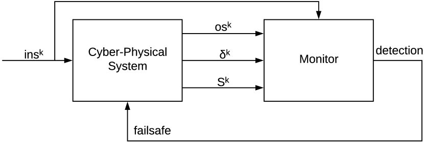
In the case of a single monitor the behavior of the cps is observed and investigated for faults and security violations by a monitor (Figure 1). As with before we denote a monitor as . We assume that the monitor observes stream of information from the target system, which includes its interactions with the environment, and sends the a fail-safe state when an abnormal condition, for example, fault or attack, is detected. These streams can be discrete or continuous time states, sensor data, instructions, or other external states, for example, gps, time, etc. Due to the reactive nature of cps, we view streams of information from a historical perspective. That is, from the current state of the cps to states previous in time, or past time temporal observations.
Each stream can be a sequence of inputs or outputs to and from the cps for each point in time. We denote the th prefix for past instances of an infinite stream, as . Thus, the stream at an instance includes information of the past instances starting with and ending at the current instance .
The monitor also observes the control flow transitions of the cps, to keep track of the execution flow in the design. The transition flow at time is: . Hence, the monitor observes the current state of the the cps as constructed from all previous states: . The language of the monitor is defined by the set of monitored streams, , where the input stream, the output stream, the execution transition data stream, and the observed states from current time for the past instances.
The role of a monitor is to answer the proposition “given a set of monitored streams from a process, did the proper sequence of operations occur in that process, and is the result safe and secure” based on observed streams of sequenced events . These events can be characterized as language or alphabet of the safety monitor. In the case where these events are compromised by security exploits or faulty behavior they may not be contained in the language and are termed as the anomalous or out-of-specification events. If there is an attack, and that attack is observable and is contained in , then we want the monitor to be able to detect the attack.
The monitor also observes the control flow transitions of the cps, to keep track of the execution flow in the design. The transition flow at time , is: . Hence, the monitor observes the current state of the the cps as constructed from all previous states: . The language of the monitor is defined by the set of monitored streams, , where the input stream, the output stream, the execution transition data stream, and the observed states from current time for the past instances.
We define the attack and fault detection concept more clearly below by defining monitors that recognize safety properties of the target cps.
Definition 1 (Monitor).
Following from above, a monitor, , is a distinct module that recognizes a set of traces or streams from a target cps whose computations can be represented as a monitorable safety language (Viswanathan, 2000).
Assuming that all security violations or faults in the system are observable, then we can extend the definition as follows.
-
•
Let be a set of all observable runs which has events and conditions that are monitorable (from the monitor language ) and acted upon by monitor defined by . has one on one correspondence with monitor language .
-
•
Let be a detection predicate over the streams of data and be the set of all safe runs in the observed data stream.
-
•
Let be a condition that holds true if there exists only from the set of all observable runs.
-
•
Let be a set of bad finite prefixes (violations over ) from the set of all runs.
Then, the monitor witnesses as follows:
When the detection predicate acts on the observable data and the data is safe and has no security exploits, then it implies that only the safety runs belong to and the safety property holds.
When the detection predicate acts on the observable data and has detected a fault or an attack, then there exists at least one bad prefix with the safety run . Therefore, the safety property ceases to hold.
The above definition is provisioned on two sufficient conditions:
Condition 1.
The detection predicate(s) that define the safe execution of a run must be defined within the monitor and be under control of the monitor.
Condition 2.
External processes to the monitor cannot manipulate, gain access or view the detection predicate(s) within monitor .
Therefore, the monitor with all the observable data makes real-time safety and security assessments of the cps using the detection predicate .
A cps can have attacks at different levels of the system. The attacks can be on the inputs and outputs of the system such as on the sensors and actuators. They can also be on the communication channel such as changes in baud rate, denial of service attacks. To detect attacks at multiple levels in a system and to identify and isolate the attacks we require multiple collaborative monitors rather than a single monitor.
3.2. Extending to Multiple Monitors
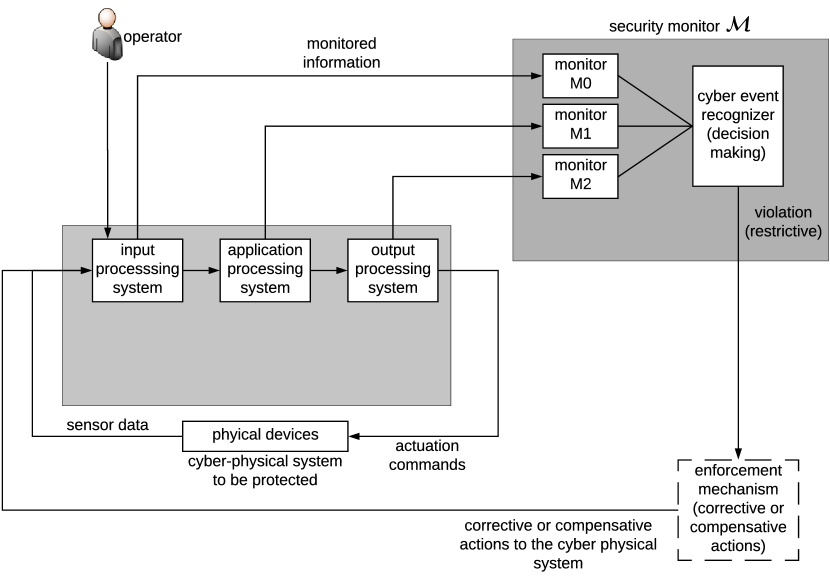
Multiple collaborative monitors observe the monitorable data and detect attacks occurring at different levels in the target system. Furthermore, multiple monitors provide many layers of defense against an attack and faster detection and isolation of an attack. The single monitor M, is extended to comprise of multiple monitors and is denoted as: (Figure 2).
The natural organization of an embedded cps suggests a specific grouping of the monitors. For example, if certain events in the cps are checked by monitor and there are prerequisite events for the monitor to make decisions which are checked by monitor , then the grouping of these two monitors follow a specific configuration. In general, monitors can be grouped as sequential, parallel, associative, and complimentary configurations (Elks, 2005).
One way to formalize and model the multiple monitor architecture and the system it targets is by reasoning in assets and their dependence relationships between these assets, , where the target cps, the multiple monitors as defined above, and the edges between monitors, between monitors and the system, and vice versa.
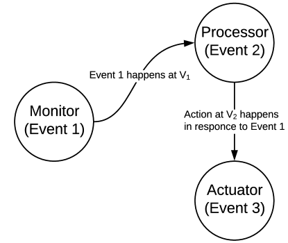
In summary, each monitor element and each system element form the vertices of the graph and the interactions between any of these elements construct the edges. The interactions among the monitors is one of the key elements of the architecture and are initiated by occurrences of events observed in the monitored stream from the cps, . To further formalize these interactions such that we can implement the detection predicates—a set of safety and security conditions/guards in the monitor—we use event calculus (Spanoudakis et al., 2007; Talcott, 2008; Franceschet and Montanari, 2000) (Figure 3).
3.3. Expressing Monitoring Events
Event calculus is a temporal language that represents properties of a system (Shanahan, 1999). Based on those properties it can, further, represent the potential consequences of an action over the system. More generally, event calculus logically describes (i) the properties that hold true in a system and (ii) when they hold true. This is determined based on two conditions: (a) “What happens and when?”: the events that occur in a system and the time at which they occur. (b) “What do actions do?”: How the action taken on a system can change the state of the fluents of the system. Here a fluent is analogous to a variable whose value can change over time. The following are standard predicates in event calculus:
-
•
means that an action happens at time .
-
•
means that an action occurs at time and a fluent starts to hold true. Fluent that holds true at the start of an operation is shown by the predicate .
-
•
, means the termination of a fluent which signifies that fluent stops being true after an action occurs at time .
-
•
shows that the fluent holds at time .
-
•
indicates that the fluent holds true between time period and .
Events are observable states in the finite prefix of a stream that express real time properties. This provides a method to describe safety and security predicates in the context of streams. If some properties are violated and the monitor detects that the system is unsafe, a mitigation strategy must commence. An example of such a strategy is to transition the system to a fail-safe mode.
The multiple monitor observe different kinds of phenomena as they pertain to the safety and security status of the cps. Ontologically, the three main domains for an exhaustive safety and security monitor are: (1) hardware integrity, (2) information integrity, and (3) execution integrity.
To construct such monitors using the formalism presented above, it is necessary to put together the graph formalism; that is, the structure, with the event calculus formalism; that is, the conditionals in which unsafe or insecure events are detected.
To do so we label the vertices and edges with a set of event calculus predicates. Meaning that for the vertices there is a subset of event occurrences . For example, for an event occurrence at vertex there might be some influence to some vertex , its response to is described through some subset of event occurrences in . Additionally, since the two vertices are dependent, an edge in exists between them.
The implication of this is that inbound edges to any provides a means for monitors to observe streams or communicate events occurring to other monitors. Whereas, outbound graph edges provide propagation of monitor decisions to other monitors or external users of confirmation of correct operations (for example, a safety property holding). The output edges can also instruct the cps to apply some mitigation strategy in the event that a threat or a fault is detected.
4. Threat Model
To understand and correctly utilize a cps security monitor we first need to understand the threat model associated with the system under evaluation. A concrete metric in this case can be the system’s attack surface—the possible entry points into the cps by an attacker. To do so, we need to enumerate the fundamental functions a given cps has to perform based on its expected service, how that functionality is realized in the specific implementation, and which parts of that implementation are observable from the outside.
Fortunately, this information is either already established for a number of cps domains (Khan et al., 2017) or there are methodologies for finding the threat model or vulnerability space for any arbitrary cps (Bakirtzis et al., 2018; Burmester et al., 2012).
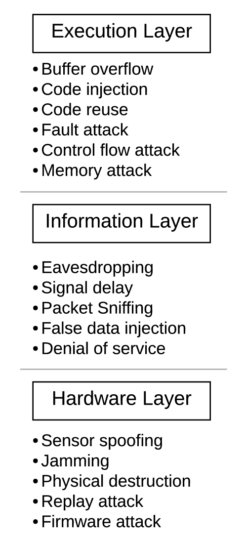
In general, there are three taxonomic levels to consider when it comes to cps security (Leccadito, 2017). The first is the phase of creation of the vulnerability in the lifecycle of the cps; that is, it can be in the development stage, maintenance stage, or operational stage. The second is the access points; that is, individual element of the attack surface. Third and final describes the types of attacks that can occur at each access points.
Therefore the threat model needs to include the hardware, information and execution layers. These are all very appealing entrance and pivoting points for an attacker. Therefore monitors are needed to counteract a possible violation at those layers. A thorough understanding of the vulnerabilities of the cps and ways of manipulating the system by an attacker is essential to monitor and defend the system against persistent threats (Figure 4).
To evaluate our methodology and monitor design we first produce a threat model for the fcs. Specifically, the fcs uses an STM32F4 ARM Cotrex-M4 168 MHz microcontroller. Additionally, it has on-board memory components, multiple peripheral options, dedicated buses for networking, components for the communications interfaces, and sensory systems (e.g., gps). This makes it a simple but comprehensive cps to produce a threat model and deploy the monitor design present in this paper.
The observable functions for the fcs are:
-
(1)
Sensor communication: the communication between the main processor and the on-board sensors.
-
(2)
Application software: the software programmed onto the main processor running the peripheral firmware.
For the first function the link between the sensors and the main processor is directly monitored. One important vulnerability that can be exploited through an attack is the violation and consequent degradation of the on-board hardware protocols. Specifically, an attacker can change the configuration of the sensors’s hardware peripheral communication protocol or inject a fault into the physical signal. Further, an attacker could exploit the firmware associated with the sensors by injecting a malicious binary version of the sensor. This can occur either at the supply chain by the manufacturer or distributor. This does need not be an insider attack, for example, in the case of Havex an attacker maliciously modified the manufacturers distribution website to infect customers (Vávra and Hromada, 2015; Rrushi et al., 2015).
For the second functions, the design is programmed into the main processors flash memory, and is monitored through a debug interface such as jtag or swd. An attacker can exploit this interface by code injection, where an attacker injects shell code on stack and overwrites the return address. Specifically, code injection attempts to cause a buffer overflow; that is, write more data than the allocated memory size which leads to the return address to be overwritten. By doing this, the control flow of the program changes in unpredictable ways.
5. Evaluation
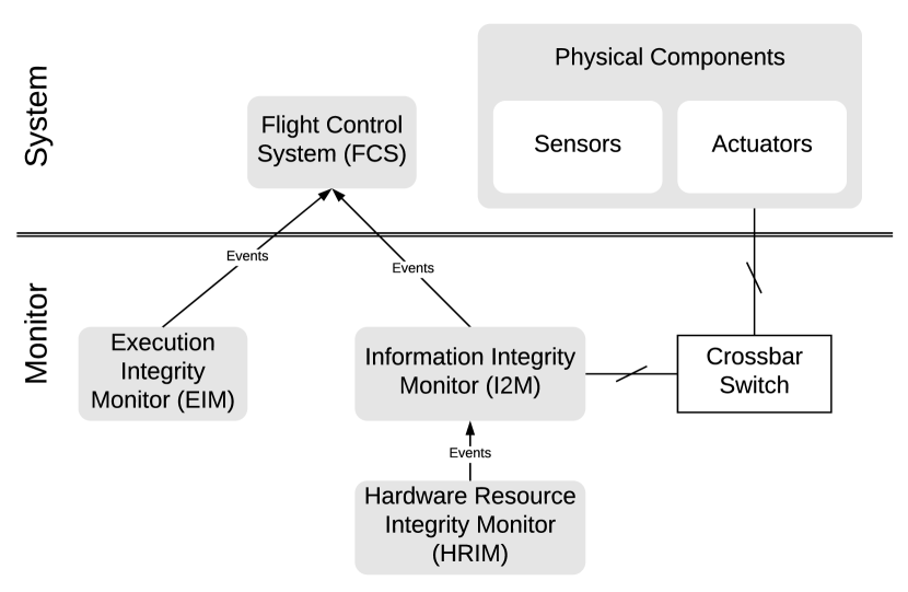
The implementation of the multilayer monitor architecture contains a hardware resource integrity monitor (hrim), an information integrity monitor (i2m), and an execution integrity monitor (eim). Thus, covering all three major domains of vulnerability and exposure in cps.
5.1. Monitoring through Event Calculus Fluents
hrim. hrim monitors the hardware communication protocol, physical signal faults, and configuration information. This monitor has no knowledge of the sensor and receives only the bus configuration information from the bus used by the cps. It uses this information to check if the bus protocol of the sensor matches the bus configuration data received by i2m. If they match, then the sensor data is written into registers which can be accessed by i2m. If it does not, then it enables a crossbar switch, which disconnects the sensor. To mitigate, hrim attempts to reconfigure the faulty sensor and if successful, it reconnects the sensor.
The following predefined event calculus fluents are used by hrim:
-
•
sensor_okay, which indicates that the sensor is in expected working condition and, therefore, no fault or security violation has been found.
-
•
bus_config_okay, which indicates that the communication bus is working as expected and, therefore, the communication protocol has not been tampered with.
-
•
sensor_reconfig, which attempts to mitigate a sensor that has been deemed to be under fault or security violation.
-
•
hrim_data_ready, which indicates that there is no fault or security violation detected for the data received by the system hardware.
Based on the occurrence of events in the system we define the following actions:
-
•
read_sensor_data, which indicates that the sensor data is ready to be read by other subsystems.
-
•
store_sensor_data, which indicates the sensor data is not faulty and is stored in data registers that could be thereby be read by other subsystems.
-
•
cross_bar_en, which indicates the sensor is faulty and crossbar is enabled to disconnect the sensor.
-
•
i2m_send_InfoToDisconnect, which makes the i2m to send sensor information to hrim when it has to disconnect the faulty sensor as hrim has no knowledge of the sensor.
Having predefined some baseline fluents and actions we can now define the behavior of hrim through a sequential pattern of events:
-
(1)
;
-
(2)
;
-
(3)
;
-
(4)
.
i2m. i2m monitors the integrity of the data received from hrim by performing certain data verification actions to detect potential attacks. It also checks for subsystem inactivity and repeated values. Specifically, it waits for the data ready signal from the hrim, hrim_data_ready, and reads the sensor data from the hrim data registers when it is ready. If the sensor is has no detected faults or security violations and the data ready signal is not received after a certain predefined time , then i2m enables the cross bar switch and disconnects the sensor. After reading the sensor data, i2m additionally verifies the data by performing data integrity checks. If the sensor data passes the verification tests, the data is ready to be used by the cps.
The following are the predefined fluents for i2m:
-
•
sensor_idle, which indicates that the sensor is idle. This is the initial state of the sensor.
-
•
i2m_parse_data_success, which indicates that i2m has performed integrity checks on the data received from hrim and the data has no faults or detected security violations.
-
•
i2m_data_ready, which indicates that the data is not faulty and lets i2m write this data into registers to be read by other subsystems.
We extend the possible actions given the requirements of i2m.
-
•
i2m_read_data, which indicates i2m reads data from the registers. The data is written to the registers by hrim.
-
•
i2m_parse_data, whcih indicates that i2m performs integrity checks on the data read from the registers.
-
•
store_I2M_data, I2M stores the non-faulty data on to registers that can be read by other subsystems after data verification.
Following these definitions, the pattern of i2m is as follows:
-
(1)
;
-
(2)
;
-
(3)
;
-
(4)
;
-
(5)
;
-
(6)
.
eim. eim first checks the firmware by comparing the memory against the static memory contents stored in the processor. If the firmware is acting as expected, then the monitor signals the application to execute the program. Moreover, it monitors the memory addresses during branching operations and ensures that the return addresses and memory addresses during jump and call instructions are not tampered.
The predefined fluents of eim are:
-
•
firmware_ok, which indicates the firmware is verified.
-
•
control_flow_ok, which indicates that the control flow is verified.
The following actions are taken by eim depending on the occurrence of events in the system:
-
•
check_firmware_ok, which checks that the firmware in in an expected state by comparing the memory to the static memory contents stored in the processor.
-
•
check_control_flow_ok, which checks two things, (1) the control flow of the program and (2) potential tampering with return addresses during jump and call instructions.
-
•
execute_program, which checks for control flow of the design—this happens only after verifying the correct operation of the firmware and memory of the cps.
-
•
fail_safe, which forces the cps to jump the execution to a failsafe part of the program in the event of a detected fault or security violation.
The patterns of events occurring in the system that are monitored by eim are:
-
(1)
;
-
(2)
;
-
(3)
;
-
(4)
.
5.2. Implementation
The hrim and i2m monitors were implemented on a Nexys 4 ddr which is a ready to use development platform based on Xilinx Artix-7 XC7A100T fpga. An fpga board has customizable features, simulation capabilities, observability and testability that makes it advantageous to implement hrim and i2m (Leccadito, 2017). Instead, the eim monitor is implemented on a processor—a more flexible platform for the complex detection techniques it implements. Specifically, we implemented eim on a Raspberry Pi 2 with OpenOCD running on it. OpenOCD is an open source software used for hardware debugging. Additionally, OpenOCD has a debug adapter which supports transport protocols such as jtag and swd (Rath, 2005). To test the multilayer architecture presented in this paper we implement monitors for a custom fcs, which in turn is implemented on STM32F407VGT6 arm cortex microprocessor (Ward et al., 2014).
The design principles and patterns governing the monitoring systems are based on the event calculus pattern sequences (Section 5.1). This allows us to use a formal model to understand acceptable and unacceptable states the system might transition too. Therefore, constructing a well-formed detection mechanism at the different layers of the monitoring architecture.
The implementation of the multilevel monitor architecture has a clear boundary between the system and the monitoring layers (Figure 5). Specifically, two of the monitors are connected serially since they need to cooperate when producing a decision and, consequently, a mitigative action; that is, the monitor checking for hardware integrity and the monitor that checks information integrity. On the other hand, the execution monitor is connected in parallel checking the actual program execution of low-level primitives. A crossbar switch is used to decouple the digital system from physical actions. This is to avoid an attacker to take advantage of either the system or the monitors to violate a physical property.
5.3. Example Results & Discussion
5.3.1. Hardware Integrity Monitor
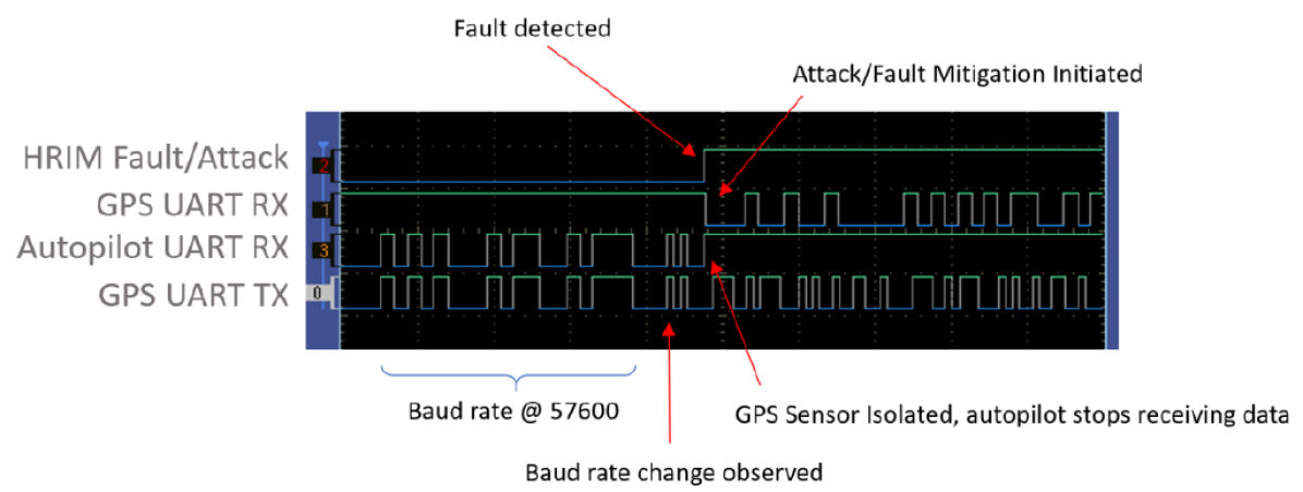
To demonstrate the fault detection and isolation capability of hrim, we perform an experiment in which a gps sensor baud-rate is manipulated during run-time. The results of injecting a physical signal fault validates the monitor’s capabilities for detecting both security violation and intrinsic faults and demonstrates the isolation of sensors using the crossbar switch. Validating this functionality shows the utility of an fpga implementation by detecting configuration attacks and isolating a sensor in the event of a fault or security violations. To capture this functionality we capture the logic analyzer trace of the uart signals between processor and gps emulator (Figure 6).
The uart baud-rate of the autopilot and gps sensors are configures to 57600 Bd. During runtime and after the initialization sequence of the autopilot, the baud-rate is expected to remain the same. Instead, a fault was injected a few seconds after the autopilot booted up to test the detection mechanism of hrim. The monitor correctly detected the higher baud rate produces by the injected fault. In this case the monitor forces the autopilot uart receive line to idle and disconnects the gps sensor that is still sending data. Then, the mitigation sequence is initiated by i2m. Since data is being sent out of the gps sensor uart receive line the mitigation sequence is conducted correctly.
5.3.2. Information Integrity Monitor
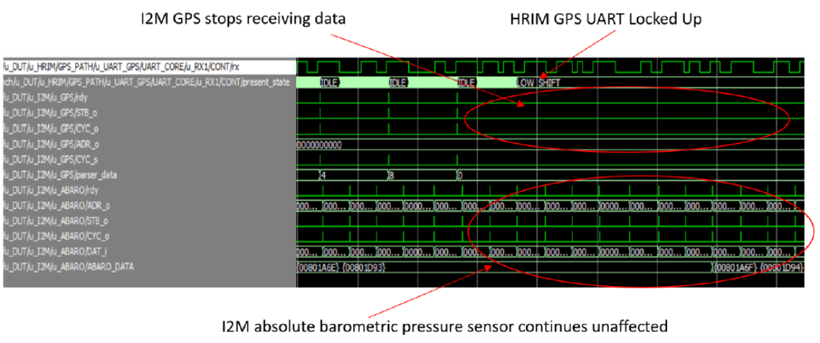
One of the tasks performed by the i2M apart from data verification is, when an attack is detected by hrim, the I2M resets, reconfigures, and reconnects the sensor to the autopilot and sends a mitigation sequence to the hrim (Figure 6). The i2m monitor also detects failure of a monitor subsystem (Figure 7). In this example, the hrim gps uart locks up and the i2m does not receive data from the sensor. Therefore triggering a fault since it expects data to be received at a specified frequency and treats it as a sensor attack due to the inactivity. It can be seen that the operation of other sensors, in the example below, that the barometric pressure sensor is unaffected. When i2m stops receiving data due to hrim gps uart lock up, it detects the fault and enables the crossbar switch in hrim which will not allow for the sensor to pass through any data to the autopilot.
5.3.3. Execution Integrity Monitor
During the execution of a program, control is transferred from one part of the program to another when there is branch instruction such as a function call or jump instruction. To ensure that there is no return address tampering attack, the eim monitors the return address during branching. If the return address is verified to be consistent and, therefore, not manipulated, then eim concludes that there has been no attack that leads to illegal control flow.
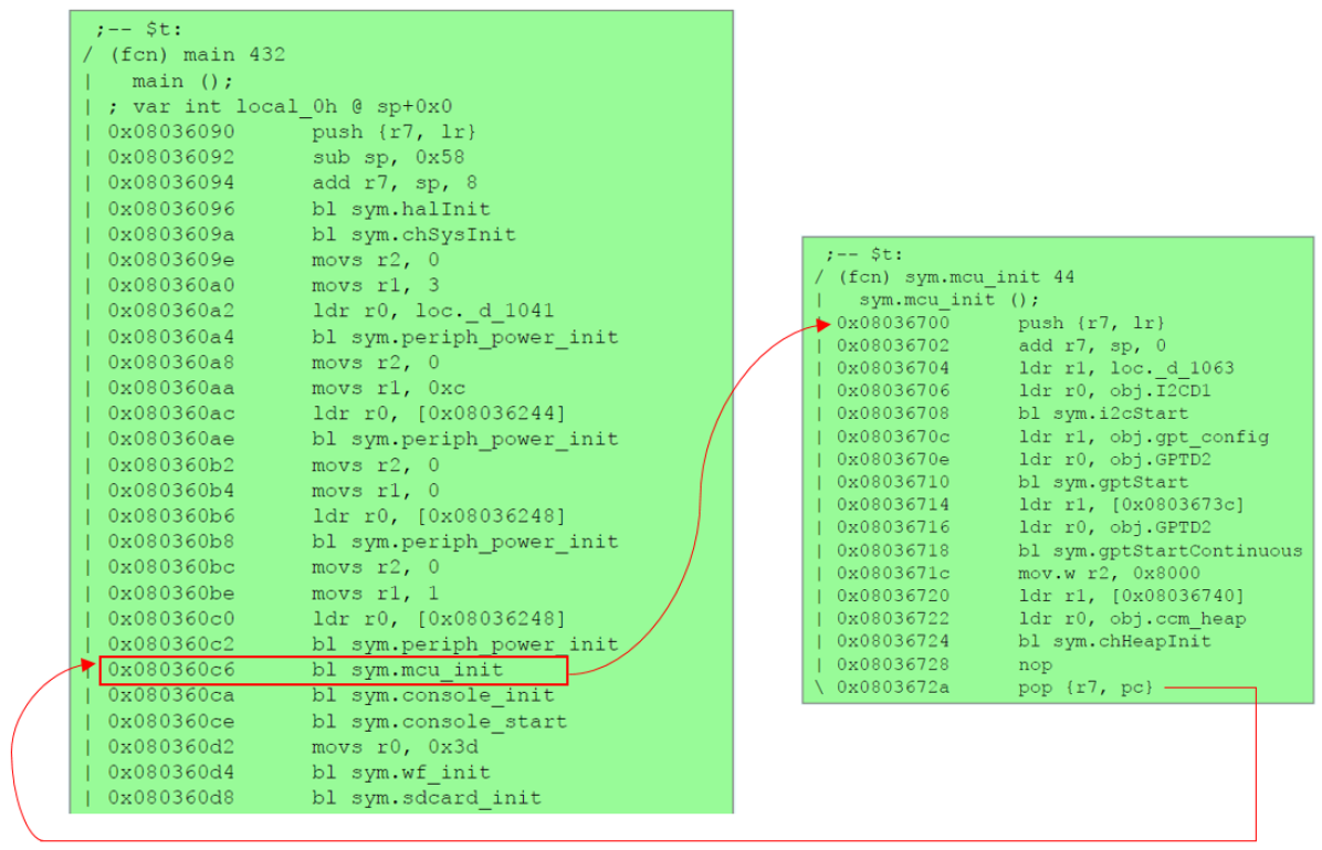
To achieve this, the eim monitor lets the application start executing only after the checking the firmware. Once the firmware is verified, the eim observes the address locations whenever there is a branching operation. As an example for execution monitoring, eim monitors the return address to the main program from a processor initialization function mcu_init whenever it has finished executing and, also, monitors the memory contents when the main program calls the mcu_init initialization function.
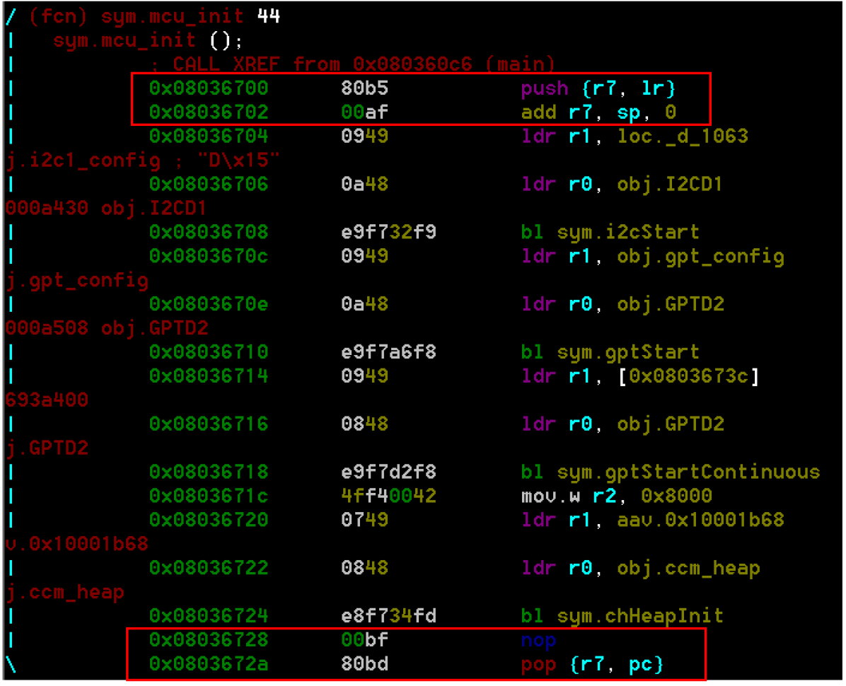
To show the operation of eim we disassembled the fcs code using Radare2—an open-source disassember (pancake, [n. d.]) (Figure 8). We visualized the information by using the dot files produced by Radare2 using graphviz (Ellson et al., 2004).
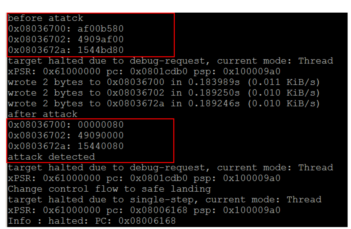
Working principle. The binary values of the branching instructions are stored in the monitor and compared at runtime. The mcu_init function is called by main (Figure 9). The branching instruction from main and the return instruction from mcu_init are compared with the copy of data stored in the monitor at runtime.
If there is an attack on the memory locations involving the branching instructions, the values at the memory locations would not match with the data stored in the monitor and it would thereby alter the control flow of the program. The output of the execution monitor is captured using OpenOCD when the program was run while simulating an attack event (Figure 10). If the monitor detects the deviation from the normal branching operation, it sends the fcs to a failsafe state by changing the control flow to a safe landing function at the location 0x08006168.
In summary, by monitoring the address locations at run time and comparing it with the control flow data, we are able to identify attacks on the system memory during branching operations. OpenOCD was used as a prototyping platform to test non intrusive monitoring of execution conditions and events in the fcs. Radare2 was used to disassemble, analyze and get a visual graphs of the functions that can be monitored using OpenOCD. Grapviz compatible dot file is generated from Radare2 to obtain call graphs for the functions to monitor. However, the execution of the full flight controller has thousands of functions and Graphviz could not generate a full call graphs. Since we only needed the main program and the function mcu_init the framework could obtain the data requirements.
6. Conclusion
We formulate a multilevel monitor comprising of hardware, information, execution monitoring using a graph of assets where the dependence conditions are defined using event calculus. Event calculus provides a semantic foundation for the design of a multiple monitor architecture. Additionally, representing the system in a formal language helps understand the design decisions made at both the level of individual subsystems in a cps and also globally at the system level. Further, the use of graphs is amenable to implement control flow with edges based on events and event calculus conditions applied to the vertices that can be mapped to security monitors.
To evaluate the proposed monitor architecture, we implement the hardware and information monitors on an fpga and the execution monitoring on a processor. We have multiple monitors to watch different layers of a cps. Multiple monitors help detect the attack faster and prevent it from affecting the rest of the system.
In the future, we plan to implement a mission monitor to observe the overall functionality of the system and check for conditions specific to the application at runtime and ensure that they hold true to further enhance the security of the cps. Furthermore, in addition to integrating monitors across different levels, it is also possible to have multiple monitors within each level which are horizontally integrated. Furthermore, another orientation for the organization of monitors is assume-guarantee compositions, which can be explored as an extension to this work.
References
- (1)
- Bakirtzis et al. (2018) Georgios Bakirtzis, Bryan T Carter, Carl R Elks, and Cody H Fleming. 2018. A model-based approach to security analysis for cyber-physical systems. In Systems Conference (SysCon), 2018 Annual IEEE International. IEEE, 1–8.
- Bateman et al. (2005) Alec Bateman, Carl Elks, David Ward, and John Schierman. 2005. New verification and validation methods for guidance/control of advanced autonomous systems. In Infotech@ Aerospace. 7117.
- Burmester et al. (2012) Mike Burmester, Emmanouil Magkos, and Vassilis Chrissikopoulos. 2012. Modeling security in cyber–physical systems. International journal of critical infrastructure protection 5, 3-4 (2012), 118–126.
- de Clercq and Verbauwhede (2017) Ruan de Clercq and Ingrid Verbauwhede. 2017. A survey of Hardware-based Control Flow Integrity (CFI). arXiv preprint arXiv:1706.07257 (2017).
- Elks (2005) Carl R Elks. 2005. A theory of run-time verification for safety critical reactive systems. University of Virginia.
- Ellson et al. (2004) John Ellson, Emden R Gansner, Eleftherios Koutsofios, Stephen C North, and Gordon Woodhull. 2004. Graphviz and dynagraph—static and dynamic graph drawing tools. In Graph drawing software. Springer, 127–148.
- Fournaris et al. (2017) Apostolos P Fournaris, Lidia Pocero Fraile, and Odysseas Koufopavlou. 2017. Exploiting hardware vulnerabilities to attack embedded system devices: a survey of potent microarchitectural attacks. Electronics 6, 3 (2017), 52.
- Franceschet and Montanari (2000) Massimo Franceschet and Angelo Montanari. 2000. A graph-theoretic approach to efficiently reason about partially ordered events in (Modal) Event Calculus. Annals of Mathematics and Artificial Intelligence 30, 1-4 (2000), 93–118.
- Havelund and Roşu (2002) Klaus Havelund and Grigore Roşu. 2002. Synthesizing monitors for safety properties. In International Conference on Tools and Algorithms for the Construction and Analysis of Systems. Springer, 342–356.
- Humayed et al. (2017) Abdulmalik Humayed, Jingqiang Lin, Fengjun Li, and Bo Luo. 2017. Cyber-physical systems security—A survey. IEEE Internet of Things Journal 4, 6 (2017), 1802–1831.
- Jacoby et al. (2011) Grant A Jacoby, IV Davis, J Nathaniel, Randolph C Marchany, et al. 2011. Detecting software attacks by monitoring electric power consumption patterns.
- Jones et al. (2014) Austin Jones, Zhaodan Kong, and Calin Belta. 2014. Anomaly detection in cyber-physical systems: A formal methods approach. In Decision and Control (CDC), 2014 IEEE 53rd Annual Conference on. IEEE, 848–853.
- Kane (2015) Aaron Kane. 2015. Runtime monitoring for safety-critical embedded systems. (2015).
- Kane et al. (2014) Aaron Kane, Thomas Fuhrman, and Philip Koopman. 2014. Monitor based oracles for cyber-physical system testing: Practical experience report. In 2014 44th Annual IEEE/IFIP International Conference on Dependable Systems and Networks. IEEE, 148–155.
- Khan et al. (2017) Rafiullah Khan, Kieran McLaughlin, David Laverty, and Sakir Sezer. 2017. STRIDE-based threat modeling for cyber-physical systems. In Innovative Smart Grid Technologies Conference Europe (ISGT-Europe), 2017 IEEE PES. IEEE, 1–6.
- Leccadito (2017) Matthew Leccadito. 2017. A Hierarchical Architectural Framework for Securing Unmanned Aerial Systems. (2017).
- Lee et al. (1998) Insup Lee, Hanene Ben-Abdallah, Sampath Kannan, Moonjoo Kim, Oleg Sokolsky, and Mahesh Viswanathan. 1998. A monitoring and checking framework for run-time correctness assurance. (1998).
- Liu et al. (2017) Yang Liu, Yu Peng, Bailing Wang, Sirui Yao, and Zihe Liu. 2017. Review on cyber-physical systems. IEEE/CAA Journal of Automatica Sinica 4, 1 (2017), 27–40.
- Lu and Forin (2007) Hong Lu and Alessandro Forin. 2007. P2V: An Architecture for Zero-Overhead Online Verification of Software Programs. In Workshop on Application Specific Processors, WASP.
- Lu et al. (2015) Tianbo Lu, Jiaxi Lin, Lingling Zhao, Yang Li, and Yong Peng. 2015. A Security Architecture in Cyber-Physical Systems: Security Theories, Analysis, Simulation and Application Fields. International Journal of Security and Its Applications 9, 7 (2015), 1–16.
- Moosbrugger et al. (2017) Patrick Moosbrugger, Kristin Y Rozier, and Johann Schumann. 2017. R2U2: monitoring and diagnosis of security threats for unmanned aerial systems. Formal Methods in System Design 51, 1 (2017), 31–61.
- pancake ([n. d.]) pancake. [n. d.]. https://www.radare.org/r/
- Papp et al. (2015) Dorottya Papp, Zhendong Ma, and Levente Buttyan. 2015. Embedded systems security: Threats, vulnerabilities, and attack taxonomy. In Privacy, Security and Trust (PST), 2015 13th Annual Conference on. IEEE, 145–152.
- Pasqualetti et al. (2013) Fabio Pasqualetti, Florian Dörfler, and Francesco Bullo. 2013. Attack detection and identification in cyber-physical systems. IEEE Trans. Automat. Control 58, 11 (2013), 2715–2729.
- Rath (2005) Dominic Rath. 2005. OpenOCD: Open on-chip debugging. Ph.D. Dissertation. Diploma Thesis, FH Augsburg.
- Rrushi et al. (2015) Julian Rrushi, Hassan Farhangi, Clay Howey, Kelly Carmichael, and Joey Dabell. 2015. A quantitative evaluation of the target selection of havex ics malware plugin. In Industrial Control System Security (ICSS) Workshop.
- Shanahan (1999) Murray Shanahan. 1999. The event calculus explained. In Artificial intelligence today. Springer, 409–430.
- Spanoudakis et al. (2007) George Spanoudakis, Christos Kloukinas, and Kelly Androutsopoulos. 2007. Towards security monitoring patterns. In Proceedings of the 2007 ACM symposium on Applied computing. ACM, 1518–1525.
- Talcott (2008) Carolyn Talcott. 2008. Cyber-physical systems and events. In Software-Intensive Systems and New Computing Paradigms. Springer, 101–115.
- Vávra and Hromada (2015) Jan Vávra and Martin Hromada. 2015. An evaluation of cyber threats to industrial control systems. In Military Technologies (ICMT), 2015 International Conference on. IEEE, 1–5.
- Viswanathan (2000) Mahesh Viswanathan. 2000. Foundations for the Run-time Analysis of Software systems. Ph.D. Dissertation. University of Pennsylvania.
- Ward et al. (2014) Garrett L Ward, Georgios Bakirtzis, and Robert H Klenke. 2014. A modular software platform for unmanned aerial vehicle autopilot systems. In 52nd Aerospace Sciences Meeting. 1050.
- Watterson and Heffernan (2007) Conal Watterson and Donal Heffernan. 2007. Runtime verification and monitoring of embedded systems. IET software 1, 5 (2007), 172–179.