Current-induced shuttlecock-like movement of non-axisymmetric chiral skyrmions
Abstract
Current-induced motion of non-axisymmetric skyrmions within angular phases of polar helimagnetis with the easy plane anisotropy is studied by micromagnetic simulations. Such non-axisymmetric skyrmions consist of a circular core and a crescent-shaped domain-wall region formed with respect to the tilted surrounding state. A current-driven motion of non-axisymmetric skyrmions exhibits two distinct time regimes: initially the skyrmions rotate towards the current flow direction and subsequently move along the current with the skyrmionic crescent first. According to the Thiele equation, the asymmetric distribution of the topological charge and the dissipative force tensor play an important role for giving the different velocities for the circular and the crescent-shaped constituent parts of the skyrmion what underlies such a shuttlecock-like movement. Moreover, the current-velocity relation depends on the tilt angle of the surrounding angular phase what makes in particular the transverse velocity of skyrmions sensitive to their field-driven configurational transformation. We also argue the possibility of magnetic racetrack waveguides based on complex interplay of robust asymmetric skyrmions with multiple twisted edge states.
pacs:
75.30.Kz, 12.39.Dc, 75.70.-i.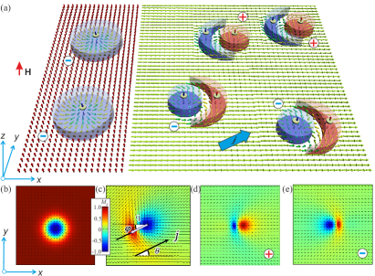
1. Introduction. Magnetic chiral skyrmions are particle-like topological excitations with complex non-coplanar spin structure Bogdanov94 ; Bogdanov89 ; Nagaosa13 ; review recently discovered in bulk non-centrosymmetric helimagnets Muehlbauer09 ; Yu10 ; Wilhelm11 ; Kezsmarki15 ; Bordacs2017 and in nanostructures with confined geometries over larger temperature regionsYu11 ; Du15 ; Liang15 . Chiral Dzyaloshinskii-Moriya interactions (DMI)Dz64 protect skyrmions from radial instability Bogdanov94 ; Leonov16a and provide a unique stabilization mechanism to overcome the constraints of the Hobart-Derrick theorem solitons . Nanometer size of skyrmions, their topological protection and the ease with which they can be manipulated by electric currents Schulz12 ; Jonietz10 ; Hsu17 opened a new active field of research in non-volatile memory and logic devices Sampaio13 ; Tomasello14 . In particular, in the skyrmion racetrack Tomasello14 ; Muller17 ; Wang16 – a prominent model for future information technology – the information flow is encoded in the moving metastable skyrmions Fert2013 .
The customary approach to enhance the functionality of the skyrmion-based racetrack memory is the mechanical patterning of underlying nanosamples. As an example, suggested devices may feature a regular arrangement of notches to divide the track into a sequence of parking lots for the skyrmions Fert2013 ; Fook16 . An additional nanostrip on top of the racetrack may create an energy barrier along the middle and thus forms two channels for a skyrmion movement Muller17 . This enables the information storage in the lane number of each skyrmion. Moreover by adding stripes with high magnetic crystalline anisotropy at the edges, one confines the skyrmions inside and prevents their escape from the nanotrack Lai17 . One should also mention elaborate schemes that include, e.g., Y-shaped junctions Zhang15 . By these, the skyrmions can be selectively driven into different nanotracks and form complementary data representation. Moreover, spin logic gates such as the ”AND” and ”OR” operations based on manipulations of skyrmions can be designed.
An alternative approach to enhance the functionality of the skyrmion-based racetrack memory is to utilize the unique properties of non-axisymmetric isolated skyrmions (NISs) that in particular may emerge within tilted ferromagnetic phases of polar magnets with the easy-plane anisotropy Leonov17 (Fig. 1 (a), right). As compared with the ordinary axisymmetric isolated skyrmions (AISs) within the field-saturated state Leonov16a (left side of Fig. 1 (a) and (b)), NIS may acquire both polarities in their cores (although the vorticity bears the same sign) and thus are subject to the skyrmion Hall effect with opposite shift directions (and hence naturally form two channels, Fig. 1 (d), (e)). Based on the opposite sign of the topological charge, one may call two types of NISs – skyrmions (Fig. 1 (d)) and anti-skyrmions (Fig. 1 (e)), and consider them as binary data bits for possible practical applications. Note that skyrmions and antiskyrmions with the same polarity but the opposite vorticity were recently investigated in frustrated magnets with competing exchange interactions Leonov17b .
In the present Letter, we explore the current-induced dynamics of introduced non-axisymmetric skyrmions. We show that depending on the direction of the spin-polarized current (SPC) with respect to the skyrmion orientation, NIS undergoes a rotation towards the SPC with its subsequent current-aligned movement. The velocity of NIS is effectively regulated by the field magnitude (and thus by the tilt angle of the surrounding angular phase). We also underline prospects of using NISs in racetrack memory devices. Anisotropic skyrmion-skyrmion interaction that depends on their mutual orientation Leonov17 alongside with the three types of edge states naturally formed at the lateral edges of a racetrack, make NISs effective candidates to be employed in nanoelectronic devices of the next generation in which nanopatterning is boiled down to a minimum.
2. Micromagnetic model. The equilibrium solutions for NIS are derived within the standard discrete model of a polar helimagnet where the total energy is given by:
| (1) |
is the unit vector in the direction of the magnetization at the site of a two-dimensional square lattice and denote pairs of nearest-neighbor spins. and are unit vectors along and directions, respectively. The first term describes the ferromagnetic nearest-neighbor exchange with , the second term is the Zeeman interaction, and the third term is the easy-plane anisotropy with . Throughout the paper, we use the value of that enables only an angular phase formation, i.e. we omit the regions of the phase diagram that host modulated skyrmion, spiral and elliptical cone phases (see, e.g., Fig. 1 in Ref. Rowland2016, for details). Dzyaloshinskii-Moriya interaction (DMI) stabilizes NISs with the Néel type of the magnetization rotation. The DMI constant defines the characteristic size of skyrmions. In the following simulations, is set to . Within model (1), AISs exist as metastable excitations of the saturated state for (Fig. 1 (b)), while NISs (Fig. 1 (c)) are present for lower fields. We use , and hence .
The current-driven dynamics of NISs and AISs was simulated using Landau-Lifshitz-Gilbert (LLG) equation:
| (2) |
Here is the gyromagnetic ratio and is the Gilbert damping constant. is a local effective magnetic field, which at the site is given by . The spin transfer torque (STT) consists of the adiabatic part, , and the non-adiabatic term, , where is the coefficient proportional to the SPC density. The SPC comprises an angle with -axis (Fig. 1 (c)). An orientation of NIS is characterized by an angle between a vector, which connects centers of the circular core and the crescent (skyrmion dipole ), and -axis (Fig. 1 (c)).
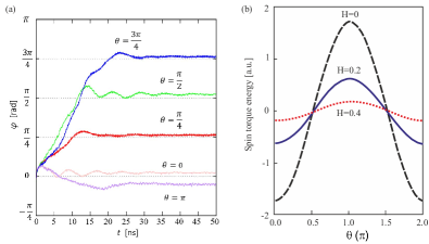
3. Current-induced motion (a shuttlecock-like movement). To systematically investigate the current-driven dynamics of NISs, we applied the SPC with different angles with respect to the skyrmion dipole initially oriented with (Fig. 2 (a)). It was found that after an initial rotation towards the SPC, NIS-dipoles are always current-aligned with (Fig. 2 (a)). A relatively small increment of the SPC angle allowed to exclude local minima of the skyrmion orientation with respect to the SPC. In particular, a NIS motion with its core along the SPC was excluded (although in a numerical experiment of Fig. 2 (a) such a movement opposite to the SPC appeared to be feasible).
A. Rotation of NIS towards the SPC direction. Figure 2 (a) shows the time dependence of the dipole angle for different SPC directions . As expected, more time is needed to orient NIS along the SPC with increasing angle . The skyrmion rotation originates from the non-axisymmetric internal structure. The spin-torque term in the LLG equation is represented by
| (3) |
and thus the energy gain due to the spin transfer torque can be expressed as . Figure 2 (b) shows the as a function of featuring minima only along the SPC. The minima, however, become shallow with the increasing magnetic field and completely disappear for with the onset of the field-saturated state that accomodates AISs.
B. Translational movement of NISs. The current-induced translational motion of NIS is well understood in terms of the Thiele equation Thiele
| (4) |
where is the velocity of the skyrmion and is the pinning potential. The gyromagnetic coupling vector equals the topological charge
| (5) |
is the dissipative force tensor:
| (6) |
which is not symmetric for NISs , even the off-diagonal element has a finite value . Thus, when the charge current is applied, the skyrmion feels both the longitudinal and the Magnus force Iwasaki13 .
For , the longitudinal and the transverse components of the velocity are represented as
| (7) | |||||
| (8) |
where .
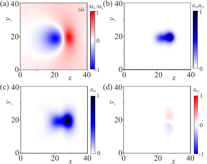
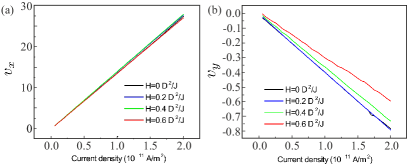
We plot the spatial configuration of the dissipative force tensor in Fig. 3 (b)-(d). With a sufficiently large value of (plotted in Fig. 3 (b)), , which is the same as for AISs Iwasaki13 and is consistent with the universal relation independent of (Fig. 4 (a)). The transverse velocity, on the contrary, is proportional to (Fig. 3 (c)) and is strongly field-dependent (Fig. 4 (b)), since the field affects the spin configuration of NISs. One can also see that of the crescent part is larger than that of the circular part (Fig. 3 (a), (b)). This asymmetry of underlies the faster velocity of the crescent resulting in the rotational motion (discussed in 3.A from another point of view). We note that the off-diagonal element of the dissipative force tensor is much smaller than and has opposite sign for upper and lower part of NISs as shown in Fig. 3 (d). Therefore, the effect of the off-diagonal element can be neglected. This is the reason why we dubbed such a motion ”a current-induced shuttlecock-like movement”. The dynamics of the NISs is shown in the Supplemental Material (SM ).
4. NISs in chiral liquid crystals. Recently, a low-voltage-driven motion of such non-axisymmetric skyrmions was realized in chiral nematic fluids ackerman2015 ; ackerman2017 ; sohn2018 with precise experimental control of both the direction and speed. Interestingly, the liquid-crystal (LC) NISs may be realized as a result of the competition between the surface anchoring and an applied electric field: whereas the surface anchoring tends to orient the director perpendicular to the confining glass plates, the electric field with the negative dielectric anisotropy – parallel to them (see in particular Fig. 1 in Ref. ackerman2017, ). As a result of such an interplay, one creates an analog of the conical phase around a skyrmion with the spin angle varying across the thickness. This induces an attractive skyrmion-skyrmion interaction and is experimentally manifested as chains of NISs ackerman2015 . Moreover, the directional motion of LC-NISs is possible as a response to modulated electric fields: when alternating current with some frequency is applied to a confined skyrmion with the axisymmetric structure (Fig. 1 (b)), it transforms back and forth into a NIS with the negative polarity (Fig. 1 (c)). NISs with the positive polarity are highly metastable solutions (Fig. 1 (d)) and have not been realized in the experiment yet. Thus, a squirming motion is induced, which can be considered as a LC counterpart of the racetrack memory suggested for magnetic skyrmions. Note that in the limit of the weak surface anchoring, LC-NISs have precisely the same structure as considered NIS in magnets with the easy-plane anisotropy (Fig. 1).
We also notice that the results obtained within the model (1) are valid for bulk polar magnets with axial symmetry as well as for thin films with interface induced DMI. In particular, bulk polar magnetic semiconductors GaV4S8 Kezsmarki15 and GaV4Se8 Bordacs2017 with the symmetry possess uniaxial anisotropy of easy-axis and easy-plane type, respectively. Since the magnitude of the effective anisotropy in these lacunar spinels strongly varies with temperature, these material family provides an ideal arena for the comprehensive study of anisotropic effects on modulated magnetic states Bordacs2017 . Skyrmions were also studied experimentally in various systems with interface induced DMI Romming13 ; Woo16 . In these thin film structures, the rotational symmetry can also be broken by different anisotropic environments due to lattice strains or reconstructions in the magnetic surface layers Hagemeister16 , as has been discussed recently for the double atomic layers of Fe on Ir(111) Hsu16 . These structural anisotropies also promote the formation of asymmetric skyrmions.
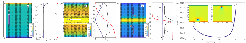
5. Edge states. The practical use of NISs in racetracks hinges on their interaction with edge states. For racetracks with the field-saturated magnetization, the edge states manifest themselves as remnants of the helical spiral and repulse AISs. For racetracks with the angular phase, however, three different types of edge states can arise (in Fig. 5 the edge states are marked with capital letters A, B, and C).
A. Transitions between edge states. The type A edge state with collinear in-plane spin components (azimuthal angle of the magnetization is ) is induced for lower values of the applied magnetic field. -component of the magnetization acquires opposite signs at the opposite edges which leads to an asymmetric NIS-edge interaction potential (Fig. 5 (d)). With increasing magnetic field, the A-type edge state undergoes the first-order transition into the type B edge state with the rotating magnetization across the racetrack width . Once reaches unit value in the racetrack middle, the B-type edge state by the second-order transition transforms into the type C edge state with (Fig. 5 (c)).
B. Orientational confinement of NISs. Three different types of edge states formed at the lateral boundaries of the racetrack also impose an orientational confinement on non-axisymmetric skyrmions. The A-type state implies the perpendicular orientation of a skyrmion dipole with respect to the racetrack edges (white arrow in Fig. 5 (a) and magnetic configurations with NISs located near both stripe edges, Fig. 5 (d)). At the same time due to the asymmetry of the magnetization distribution within the opposite edges, a NIS will be located closer to one edge than to the other (Fig. 5 (d)). The SPC , by inducing the skyrmion rotation, may also initiate a transition A-B between edge states in spite of the B-type state is a metastable solution. The B-type state, on the contrary, may accommodate NISs with . Thus, a moving NIS due to the skyrmion Hall effect will shift the whole stripe with the maximal -component (marked by the dashed lines in Fig. 5 (b)) towards one of the edges. The C-type edge state allows two opposite NIS orientations degeneracy of which could be removed by the SPC (Fig. 5 (c)).
6. Conclusions. In conclusion, we examined the current-induced dynamics of non-axisymmetric skyrmions that exist within angular phases of polar helimagnets with the easy plane anisotropy. We considered a shuttlecock-like movement of NISs that consists in their rotation to coalign with the SPC. We succeeded in modifying the current-velocity relation by the field-driven control of the angle in a surrounding homogeneous state. We also speculate that a NIS placed into the racetrack memory with three different types of the edge states not only undergoes an orientational confinement, but can also be used as a current-activated tumbler between edge states. Our results are not only relevant to the application of magnetic skyrmions in memory technology but also elucidate the fundamental properties of skyrmions and the edge states formed in the angular phases of polar helimagnets Bordacs2017 .
I Acknowledgments
The authors are grateful to Istvan Kezsmarki and Maxim Mostovoy for useful discussions. This work was funded by JSPS Core-to-Core Program, Advanced Research Networks (Japan), JSPS Grant-in-Aid for Research Activity Start-up 17H06889, Grant-in-Aid fort Scientic Research (A) 17H01052 from MEXT, Japan and CREST, JST. AOL thanks Ulrike Nitzsche for technical assistance.
References
- (1) A. Bogdanov and A. Hubert, J. Magn. Magn. Mater. 138, 255 (1994); 195, 182 (1999).
- (2) A. N. Bogdanov and D. A. Yablonskii, Zh. Eksp. Teor. Fiz. 95, 178 (1989) [Sov. Phys. JETP 68, 101 (1989)].
- (3) N. Nagaosa and Y. Tokura, Nat. Nanotechnol. 8, 899–911 (2013).
- (4) U. K. Rößler et al., J. Phys. Conf. Ser. 303, 012105 (2011).
- (5) S. Mühlbauer et al., Science 323, 915–919 (2009).
- (6) X. Z. Yu et al., Nature (London) 465, 901 (2010).
- (7) H. Wilhelm et al., Phys. Rev. Lett. 107, 127203 (2011).
- (8) I. Kezsmarki et al., Nat. Mater. 14, 1116–1122 (2015).
- (9) S. Bordacs et al., Sci. Rep. 7: 7584 (2017)
- (10) X. Z. Yu et al., Nat. Mater. 10, 106–109 (2011).
- (11) H. Du et al., Nat. Commun. 6, 7637 (2015).
- (12) D. Liang et al., Nat. Commun. 6, 8217 (2015).
- (13) I. E. Dzyaloshinskii, Sov. Phys. JETP 19, 960 (1964).
- (14) A. O. Leonov et al., New J. of Phys. 18, 065003 (2016).
- (15) R. Rajaraman, Solitons and Instantons: An Introduction to Solitons and Instantons in Quantum Field Theory (North- Holland, Amsterdam, 1982).
- (16) T. Schulz et al., Nat. Phys. 8, 301–304 (2012).
- (17) F. Jonietz et al., Science 330, 1648 (2010).
- (18) P-J. Hsu et al., Nat. Nanotechnol. 12, 123 (2017).
- (19) J. Sampaio et al., Nat. Nanotechnol. 8, 839844 (2013).
- (20) E. M. R. Tomasello et al., Sci. Rep. 4, 6784 (2014).
- (21) J. Müller, New J. Phys. 19, 025002 (2017).
- (22) K. Wang et al., Sci. Rep. 6, 23164 (2016).
- (23) A. Fert et al., Nat. Nanotechnol. 8, 152 (2013).
- (24) H. T. Fook et al., Sci. Rep. 6, 21099 (2016).
- (25) P. Lai et al.,Sci. Rep. 7, 45330 (2017).
- (26) X. Zhang et al., Sci. Rep. 5, 9400 (2015).
- (27) A. O. Leonov and I. Kezsmarki, Phys. Rev. B 96, 014423 (2017).
- (28) A. O. Leonov, M. Mostovoy, Nat. Commun. 8, 14394 (2017); Nat. Commun. 6, 8275 (2015).
- (29) J. Rowland et al., Phys. Rev. B 93, 020404 (2016).
- (30) A. A. Thiele, Phys. Rev. Lett. 30, 230–233 (1972).
- (31) J. Iwasaki et al., M. Mochizuki, and Naoto Nagaosa, Nat. Commun. 4, 1463 (2013).
- (32) See Supplemental Material for the simulation movie.
- (33) P. J. Ackerman et al., Nat. Commun. 8, 673 (2017).
- (34) P. J. Ackerman et al., Nat. Commun. 6, 6012 (2015).
- (35) H. R. O. Sohn et al., Phys. Rev. E 97, 052701 (2018).
- (36) N. Romming et al., Science 341, 636 (2013).
- (37) S. Woo et al., Nat. Mater. 15, 501 (2016).
- (38) J. Hagemeister et al., Phys. Rev. B 94, 104434 (2016).
- (39) P. J. Hsu et al., Phys. Rev. Lett. 116, 017201 (2016).