Ultrafast tunable modulation of light polarization at terahertz frequencies
Controlling light polarization is one of the most essential routines in modern optical technology. Since the demonstration of optical pulse shaping by spatial light modulators and its potential in controlling the quantum reaction pathways, it paved the way for many applications as a coherent control of the photoionization process or as polarization shaping of terahertz (THz) pulses. Here, we evidenced efficient nonresonant and noncollinear -type light-matter interaction in femtosecond polarization-sensitive time-resolved optical measurements. Such nonlinear optical interaction of visible light and ultrashort THz pulses leads to THz modulation of visible light polarization in bulk LiNbO3 crystal. Theoretical simulations based on the wave propagation equation capture the physical processes underlying this nonlinear effect. Apart from the observed tunable polarization modulation of visible pulses at ultrahigh frequencies, this physical phenomenon can be envisaged in THz depth-profiling of materials.
Over the last decade, ultrafast terahertz (THz) spectroscopy has gained tremendous attention thanks to the development of high power ultrafast laser systems [1], which allowed the generation of intense single-cycle picosecond pulses of electric field at THz frequencies [2, 3]. Their relatively long optical cycle period (1 ps for 1 THz) and high electric field (from hundreds of kV/cm to a few MV/cm) provide a new tool for studying fundamental aspects of light-matter interactions like THz-driven ballistic charge currents in semiconductors [4, 5], linear [6] and nonlinear [7] control of antiferromagnetic spin waves, THz-induced dynamics in metallic ferromagnets [8] and transparent magneto-optical media [9], or even an ultrafast switching of electric polarization in ferroelectrics [10]. Field-resolved detection of ultrashort THz pulses has been well known for many years, and the most common technique is based on free-space electro-optic sampling, which can be implemented in two ways: non phase-matched electro-optic sampling in crystals like ZnTe [11] or GaP [12] and phase-matched electro-optic sampling in a GaSe crystal [13, 14]. The latter relies on phase-matched propagation of THz and visible pulses in a crystal leading to an efficient ordinary-to-extraordinary conversion for visible photons at approximately the same frequency, . This leads to the polarization change of an optical pulse, which is detected by the polarization-sensitive scheme, and to the field resolved detection of a THz pulse. Since nonresonant THz induced optical nonlinearities in dielectric crystals are nearly instantaneous, the magnitude of the polarization change should be determined solely by the spatiotemporal dynamics of interacting THz and visible pulses propagating inside the crystal. Consequently, the polarization switching time lies in the picosecond range governed by the duration of the pulses involved. In other words, such nonresonant nonlinear optical interactions set the fundamental speed limits of electro-optical modulation, which is limited to nanosecond switching time for conventional electro-optic devices [15]. Although phase-matched electro-optics seems to be appealing to achieve ultrafast control over the polarization state of light, to the best of our knowledge, it has been only applied to detect and characterize THz fields. Moreover, the relatively low efficiency and the third-order optical nonlinearity in a GaSe crystal are limiting its impact [16].
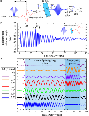
Here we report on the efficient modulation of light’s polarization by THz ultrashort pulses via the second-order nonlinear optical interaction inside a LiNbO3 crystal, where an intense THz pump and a visible probe pulse interact during their propagation inside the crystal of thickness 1 mm. Optical properties of visible probe pulses are monitored by polarization sensitive measurements (rotation and ellipticity) as a function of the pump-probe delay time. Two distinct (front-side and back-side) probing configurations are sketched in Fig. 1 (a) and in the inset of Fig. 1 (b), respectively. The maximum THz electric field amplitude on the sample is in the order of 100 kV/cm. Fig. 1 (b) shows a typical pump-probe transient measured in the back-side probing configuration at 400 nm probe wavelength and (). Due to the polarization-sensitive detection scheme with a half waveplate, the measured signal is linked to the rotation of the polarization state of the visible probe pulses induced by nonlinear optical interaction with the THz pulses propagating in the crystal and exhibits time domain oscillations at two distinct frequencies of 0.22 THz (low frequency ) and 0.69 THz (high-frequency ), respectively. For this particular experimental configuration, the rotation angle, denoted as the polarization rotation angle , is approximately , which corresponds to a polarization conversion efficiency of . A similar transient shape is observed when measuring the ellipticity change with a quarter-wave plate (not shown). Moreover, the signals are of comparable amplitude when measuring the rotation or ellipticity changes, but they are phase-shifted by roughly , which means that the rotation is maximum when the ellipticity is 0 and vice versa. The occurrence of high-frequency and low-frequency can be uniquely attributed to copropagating and counterpropagating THz and visible pulses, respectively. The frequency changes from high to low, and vice versa, each time the THz pulse is reflected at one of the crystal surfaces. The alternating time windows for the observation of copropagating and counterpropagating THz and visible pulses inside the crystal of thickness L= 1 mm (see Fig 1 (b)) are governed by group velocities,
| (1) |
with the index of light polarized along the ordinary and the refractive index of the THz pulse, considering that the LiNbO3 is not dispersive in this frequency range. The different time intervals are experimentally found to be 12.1 ps and 32.3 ps, and, considering the value of the visible group refractive index, one can extract the THz ordinary refractive index , which is in good agreement with the literature [17, 18]. Finally the signal duration of hundreds of picoseconds and the drops in amplitude for each reflection at the interfaces are explained by the absorption coefficient of the LiNbO3 in the THz spectral range and by the THz reflection coefficient, which is roughly 75% for the field amplitude.
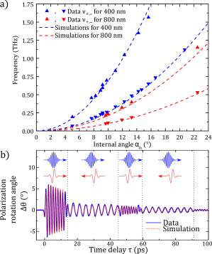
Measurements at different probe angles ranging from 0 to 16∘ have been performed and are displayed in Fig. 1 (c) for a probe’s wavelength nm. The curve at 0∘ reflects interfacial effect as described below. On top of this effect, noncollinear geometry gives birth to the single low and high frequencies, which increase continuously as a function of the angle . Systematic investigation of the evolution of the observed frequencies versus the probe angles and for two wavelengths nm and nm was carried out and is displayed in Fig. 2 (a). For each wavelength, two frequency branches ( and ) appear, which correspond to co- and counter-propagating THz and visible pulses as described previously. The maximum measured frequency is 1.6 THz () for nm and 1.1 THz () for nm. Dashed lines correspond to the results of the theoretical solution based on our model, which is summarized by Eq. (2), and are perfectly in agreement with experimental results. Fig. 2 (b) demonstrates perfect agreement between the experimental and simulated polarization rotation in time domain.
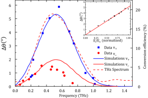
For a quantitative insight into the nonlinear process involved here, we have measured the amplitude of the change of the light’s polarization angle while sweeping the internal angle for a wavelength of 400 nm. In Fig. 3, of the first occurring oscillations ( or ) is plotted as a function of the frequencies for the two experimental configurations namely the front-side and back-side probing geometries. The first striking feature is the measured maximum polarization rotation angle, occurring at 0.6 THz for , which is as high as . This corresponds to a light polarization conversion efficiency of 20% upon the presence of the THz pulse. This light’s polarization rotation angle is the largest, for the considered THz field amplitude, reported so far in the literature (in the order of 1 degree in ultrafast experiments [8, 19]). Furthermore, unlike GaSe [16], no saturation effect is evidenced (see the inset of Fig. 3), opening the way to improving conversion efficiency. The second striking feature is the difference in the maximum rotation angle for and with a almost 3 times higher amplitude for . Along with the experimental data points, the results of numerical evaluation of the analytical theoretical prediction of time integration of Eq. (2) are plotted for both co- () and counter-propagating () pulses. These are in a good agreement with the experimental results. Moreover, the spectral amplitude of the polarization rotation transients is proportional to the spectral components of the THz pulse used in the experiments shown in the dashed line in Fig. 3. In light of these results, the main effect of tuning the angle is to fulfill the phase-matching condition for different frequency components contained in the pump THz spectrum, which directly leads to the THz pulse sampling in the frequency domain and, thus, allows to adjust the modulation frequency of the probe pulse.
The experimental results were analysed by theoretical simulations of the scattering process between the light and THz pulses within the sample. We considered second-order nonlinear interaction between the electric field of the ordinary polarized THz pulse and of the ordinary polarized visible probe, leading to the generation of an extraordinary optical beam. Solving the wave propagation equation for the extraordinary beam generated by this interaction leads to the expression for the signal amplitude as the function of the time delay between the THz pump and the optical probe beam, which is governed by an interplay between distinct phase- and group-matching conditions for visible and THz electromagnetic fields. For the half-wave plate and Wollaston prism arrangement, the theoretical modelling gives
| (2) | ||||
where is the nonlinear optical coefficient, with is the wave vector for the ordinary or extraordinary polarized visible light respectively and is a slowly varying envelope of the optical probe pulse. and stand for co-propagating and counter-propagating pulses, respectively. The photodetector signal is the time integral of Eq. (2) and leads to the time evolution of the polarization state (rotation and ellipticity) of the probe beam. The simulated transient (see figure 2 (b)) gives information about the modulation frequency and the amplitude as a function of the angle . Multiple reflections can also be simulated. In our model, we only consider the second-order nonlinear effect occurring in the bulk of the crystal. In the simulations, there are no free parameters: the model requires only the parameters of the material and of the pulse, which are determined independently. The simulated transients are in excellent agreement with the experimental ones as we included the reflection coefficient as well as the THz absorption of the crystal (see Fig. 2 (b)). The computed frequencies of the oscillations versus the angle are displayed in dashed lines in Fig. 2 and perfectly agree the experimental observation for two different wavelengths. There is as well a good agreement between the calculated and measured amplitudes of the oscillations, which are displayed in Fig. 3 with only a scaling factor. It is interesting to note that the ratio of the and simulated amplitudes is frequency independent and is equal to 2.7. This ratio can be explained by the longer interaction time of the THz pulse with the co-propagating light field than with the counter-propagating one, , agreeing with the experimental value of . Deviation of the numerical simulation starting at around 0.4 THz for the back-side configuration, corresponding to an angle (), can be explained by the geometrical effect of the beams crossing in the sample which is neglected in our model.
We now discuss the physical effect underlying the THz controlled polarization rotation of the visible probe pulse. In conventional non phase-matched free-space electro-optic sampling, in ZnTe crystal for instance, the THz and optical gate pulses are group-matched. Thus, the optical probe pulse accumulates a phase shift at a constant rate during the propagation in the crystal proportional to the THz electric field value set by the relative time delay between the pulses. This technique has been widely used for decades in linear and nonlinear THz spectroscopy [20] and provides a sampling of the THz pulse in time domain by the light pulse. Moreover, the effect exists both for collinear [21, 22] and noncollinear [23] propagation of THz and light pulses. In the case of LiNbO3, the optical and THz group indices are mismatched by roughly a factor of 2, which leads to a different interpretation of our experimental results. The observed experimental signals have two origins: from the interface region and from the bulk. The effect of the interface region can be clearly seen in Fig. 1 (c) for at and 47 ps corresponding to the injection or reflection of THz pulses from the surface as seen by the optical probe. Consequently, the non-zero polarization rotation will be proportional to . Once the THz pulse is completely inside the crystal, the polarization rotation accumulated by the optical pulse will be proportional to the integral of the THz pulse and, thus, leads to no detectable signal. It has to be noted that the observed ”interfacial” effect exploits the substantial group mismatch between the optical and THz pulses (common for most materials) and can be used to retrieve the temporal THz pulse shape. The periodic oscillation of the signal relies on the complex interplay between phase and group-matching conditions (see Eq. (2)) due to optical second order nonlinear effect occurring inside the sample and is observed only for noncollinear propagation of the THz and light pulses. Its frequency can be adjusted by tuning the angle between the two incident beams. The angular dependence of the oscillation amplitude makes possible to retrieve the THz spectrum as shown in Fig. 3.
One potential application would be to use picosecond pulses of visible light with a pulse duration roughly equal to or . This configuration would lead to an ultrafast periodic modulation of the polarization state of the visible light at THz frequency, depending on the crossing angle between THz and optical pulses. As the modulation frequency can be modified easily it can be tuned to resonantly drive systems like coherent THz optical phonon excitation in solids [24, 25] and Raman-active media [26] for example. Another possible application of our experimental scheme is to add the third (axial) coordinate to the well-known ”2D imaging with THz waves” [27, 28, 29, 30], which currently provides only lateral resolution. The micrometer axial resolution for depth-profiling of the suggested three-dimensional imaging technique is controlled by the spatial overlap of the THz and probe light pulses and, in case of their counter-propagation, could outperform the ”echography with THz pulses” [31].
In conclusion, we have experimentally demonstrated an ultrafast tunable polarization modulation of optical pulses at a wavelength of 400 and 800 nm caused by nonresonant interaction with an ultrashort THz pulse in LiNbO3 crystal. The maximum polarization rotation and ellipticity was measured to be and at the internal angle of between the THz pulse and a 400 nm visible probe. This effect is modelled by solving the wave propagation equation, and analytical expressions show that an interplay between distinct phase- and group-matching conditions for visible and THz electromagnetic fields determines the overall conversion efficiency. Being in excellent agreement with theoretical calculations, our experimental findings pave the way to the design of ultrafast and efficient miniaturized electro-optical devices for pulse shaping operating in the multi-THz range.
Funding
Campus France; Région Pays de la Loire (NNN-Telecom, Ultrasfast Acoustics in Hybrid Magnetic Nanostructures and Echopico projects).
References
- [1] T. Kampfrath, K. Tanaka, and K. A. Nelson, “Resonant and nonresonant control over matter and light by intense terahertz transients,” Nature Photonics, vol. 7, no. 9, pp. 680–690, 2013.
- [2] K.-L. Yeh, M. Hoffmann, J. Hebling, and K. A. Nelson, “Generation of 10 j ultrashort terahertz pulses by optical rectification,” Applied Physics Letters, vol. 90, no. 17, p. 171121, 2007.
- [3] H. Hirori, A. Doi, F. Blanchard, and K. Tanaka, “Single-cycle terahertz pulses with amplitudes exceeding 1 mv/cm generated by optical rectification in linbo3,” Applied Physics Letters, vol. 98, no. 9, p. 091106, 2011.
- [4] W. Kuehn, P. Gaal, K. Reimann, M. Woerner, T. Elsaesser, and R. Hey, “Coherent ballistic motion of electrons in a periodic potential,” Physical review letters, vol. 104, no. 14, p. 146602, 2010.
- [5] O. Schubert, M. Hohenleutner, F. Langer, B. Urbanek, C. Lange, U. Huttner, D. Golde, T. Meier, M. Kira, S. W. Koch, and R. Hubert, “Sub-cycle control of terahertz high-harmonic generation by dynamical bloch oscillations,” Nature Photonics, vol. 8, no. 2, pp. 119–123, 2014.
- [6] T. Kampfrath, A. Sell, G. Klatt, A. Pashkin, S. Mährlein, T. Dekorsy, M. Wolf, M. Fiebig, A. Leitenstorfer, and R. Huber, “Coherent terahertz control of antiferromagnetic spin waves,” Nature Photonics, vol. 5, no. 1, pp. 31–34, 2011.
- [7] S. Baierl, M. Hohenleutner, T. Kampfrath, A. Zvezdin, A. Kimel, R. Huber, and R. Mikhaylovskiy, “Nonlinear spin control by terahertz-driven anisotropy fields,” Nature Photonics, 2016.
- [8] C. Vicario, C. Ruchert, F. Ardana-Lamas, P. M. Derlet, B. Tudu, J. Luning, and C. P. Hauri, “Off-resonant magnetization dynamics phase-locked to an intense phase-stable terahertz transient,” Nature Photonics, vol. 7, no. 9, pp. 720–723, 2013.
- [9] R. Subkhangulov, R. Mikhaylovskiy, A. Zvezdin, V. Kruglyak, T. Rasing, and A. Kimel, “Terahertz modulation of the faraday rotation by laser pulses via the optical kerr effect,” Nature Photonics, 2016.
- [10] R. Mankowsky, A. von Hoegen, M. Först, and A. Cavalleri, “Ultrafast reversal of the ferroelectric polarization,” Physical Review Letters, vol. 118, no. 19, p. 197601, 2017.
- [11] P. C. Planken, H.-K. Nienhuys, H. J. Bakker, and T. Wenckebach, “Measurement and calculation of the orientation dependence of terahertz pulse detection in znte,” JOSA B, vol. 18, no. 3, pp. 313–317, 2001.
- [12] Q. Wu and X.-C. Zhang, “7 terahertz broadband gap electro-optic sensor,” Applied Physics Letters, vol. 70, no. 14, pp. 1784–1786, 1997.
- [13] C. Kübler, R. Huber, S. Tübel, and A. Leitenstorfer, “Ultrabroadband detection of multi-terahertz field transients with gase electro-optic sensors: Approaching the near infrared,” Applied physics letters, vol. 85, no. 16, pp. 3360–3362, 2004.
- [14] K. Liu, J. Xu, and X.-C. Zhang, “Gase crystals for broadband terahertz wave detection,” Applied physics letters, vol. 85, no. 6, pp. 863–865, 2004.
- [15] Y.-q. Lu, M. Xiao, and G. J. Salamo, “Wide-bandwidth high-frequency electro-optic modulator based on periodically poled linbo3,” Applied Physics Letters, vol. 78, no. 8, pp. 1035–1037, 2001.
- [16] A. Sell, A. Leitenstorfer, and R. Huber, “Phase-locked generation and field-resolved detection of widely tunable terahertz pulses with amplitudes exceeding 100 mv/cm,” Optics letters, vol. 33, no. 23, pp. 2767–2769, 2008.
- [17] M. Schall, H. Helm, and S. Keiding, “Far infrared properties of electro-optic crystals measured by thz time-domain spectroscopy,” International journal of infrared and millimeter waves, vol. 20, no. 4, pp. 595–604, 1999.
- [18] M. Unferdorben, Z. Szaller, I. Hajdara, J. Hebling, and L. Pálfalvi, “Measurement of refractive index and absorption coefficient of congruent and stoichiometric lithium niobate in the terahertz range,” Journal of Infrared, Millimeter, and Terahertz Waves, vol. 36, no. 12, pp. 1203–1209, 2015.
- [19] R. V. Mikhaylovskiy, R. R. Subkhangulov, T. Rasing, and A. V. Kimel, “Colossal magneto-optical modulation at terahertz frequencies by counterpropagating femtosecond laser pulses in tb3ga5o,” Optics letters, vol. 41, no. 21, pp. 5071–5073, 2016.
- [20] D. Grischkowsky, S. Keiding, M. Van Exter, and C. Fattinger, “Far-infrared time-domain spectroscopy with terahertz beams of dielectrics and semiconductors,” JOSA B, vol. 7, no. 10, pp. 2006–2015, 1990.
- [21] M. Van Exter, C. Fattinger, and D. Grischkowsky, “High-brightness terahertz beams characterized with an ultrafast detector,” Applied Physics Letters, vol. 55, no. 4, pp. 337–339, 1989.
- [22] Q. Wu and X.-C. Zhang, “Free-space electro-optic sampling of terahertz beams,” Applied Physics Letters, vol. 67, no. 24, pp. 3523–3525, 1995.
- [23] J. Shan, A. S. Weling, E. Knoesel, L. Bartels, M. Bonn, A. Nahata, G. A. Reider, and T. F. Heinz, “Single-shot measurement of terahertz electromagnetic pulses by use of electro-optic sampling,” Optics letters, vol. 25, no. 6, pp. 426–428, 2000.
- [24] K. Sokolowski-Tinten, C. Blome, J. Blums, A. Cavalleri, C. Dietrich, A. Tarasevitch, I. Uschmann, E. Förster, M. Kammler, M. Horn-von Hoegen, and D. von der Linde, “Femtosecond x-ray measurement of coherent lattice vibrations near the lindemann stability limit,” Nature, vol. 422, no. 6929, pp. 287–289, 2003.
- [25] D. M. Fritz and et al, “Ultrafast bond softening in bismuth: Mapping a solid’s interatomic potential with x-rays,” Science, vol. 315, no. 5812, pp. 633–636, 2007.
- [26] K. Misawa, “Applications of polarization-shaped femtosecond laser pulses,” Advances in Physics: X, vol. 1, no. 4, pp. 544–569, 2016.
- [27] B. Hu and M. Nuss, “Imaging with terahertz waves,” Optics letters, vol. 20, no. 16, pp. 1716–1718, 1995.
- [28] Q. Wu, T. Hewitt, and X.-C. Zhang, “Two-dimensional electro-optic imaging of thz beams,” Applied Physics Letters, vol. 69, no. 8, pp. 1026–1028, 1996.
- [29] M. C. Nuss, “Chemistry is right for t-ray imaging,” IEEE Circuits and Devices Magazine, vol. 12, no. 2, pp. 25–30, 1996.
- [30] A. Fitzgerald, E. Berry, N. Zinovev, G. Walker, M. Smith, and J. Chamberlain, “An introduction to medical imaging with coherent terahertz frequency radiation,” Physics in Medicine and biology, vol. 47, no. 7, p. R67, 2002.
- [31] J. B. Jackson, J. Labaune, R. Bailleul-Lesuer, L. D’Alessandro, A. Whyte, J. W. Bowen, M. Menu, and G. Mourou, “Terahertz pulse imaging in archaeology,” Frontiers of Optoelectronics, vol. 8, no. 1, pp. 81–92, 2015.