Alfvénic gap eigenmode in a linear plasma with ending magnetic throats
Abstract
To guide the experimental design of a linear plasma device for studying the interaction between energetic ions and Alfvénic gap eigenmode (AGE), this work computes AGE referring to fusion conditions in a ultra-long large plasma cylinder ended with strong magnetic throats for axial confinement of charged particles. It is shown that: (i) for uniform equilibrium field between the ending throats, the dispersion relation of computed wave field agrees well with a simple analytical model for shear Alfvénic mode; (ii) for periodic equilibrium field with local defect, clear AGE is formed inside spectral gap for both low and high depths of magnetic throats, although lower depth yields easier observation. The strongest AGE can be in order of to equilibrium field, making it conveniently measurable in experiment. The AGE is a standing wave localized around the defect which is introduced to break the system’s periodicity, and its wavelength is twice the system’s period, consistent with Bragg’s law. Parameter scan reveals that the AGE remains nearly the same when the number of magnetic ripples is reduced from to , however, there occurs an upward frequency shift when the depth of magnetic ripples drops from to , possibly due to a flute-like effect: shrinking resonant cavity of spectral gap.
I Introduction
Alfvénic instabilities that are driven unstable by energetic particles in fusion plasmas can in turn expel these particles from magnetic confinement, threatening the operation of magnetic fusion reaction.Duong:1993aa ; White:1995aa ; Wong:1999aa ; Breizman:2011aa Alfvénic gap eigenmode (AGE), a discrete eigenmode inside spectral gap and free of continuum damping, is the most easily excited mode that requires particular attention.Heidbrink:2008aa ; Cheng:1985aa ; Fasoli:1996aa Schematics of general spectral gap and gap eigenmode inside are illustrated in Fig. 1, which are defined as: a gap in continuous spectrum where waves are evanescent, and a discrete eigenmode with frequency inside the gap, respectively.Strutt:1887aa ; Mott:1968aa ; Figotin:1997aa ; Kittel:1996aa Characterizing the interaction physics between AGE and energetic particles especially ions attracts great interest in the past but is mainly based on traditional fusion devices such as tokamak and stellarator.ITER:1999aa ; ITER:2007ab Because of low cost, simple geometry, easy diagnostic and flexible length, linear plasma is becoming a promising candidate to study fundamental physics occurred in toroidal fusion plasmas, based on its outstanding spatial and temporal diagnostic resolutions.Gekelman:1991aa ; Blackwell:2012aa ; Rapp:2017aa
The attempt to form AGE in a linear plasma can date back to 2008, when Alfvénic spectral gap was observed experimentally in a large plasma cylinder, by setting up a longitudinal array of periodic magnetic mirrors according to Bragg’s reflection; however, discrete eigenmode was not yet formed inside this gap.Zhang:2008aa To guide the experimental implementation of this gap eigenmode, theoretical analyses and numerical computations were carried out, first on whistlers and then on Alfvénic modes.Chang:2013aa ; Chang:2014aa ; Chang:2016aa ; Chang:2016ab ; Chang:2018aa But all these attempts did not consider the loss of energetic particles through the ends of plasma cylinder, which is nevertheless very important for designing a real machine. Recently, ultra-long large plasma cylinder ended with strong magnetic mirrors is proposed by several institutions to study the fundamental physics of the interaction between energetic ions and AGE in fusion plasmas.Chen:2017aa ; Wang:2017aa ; Peng:2017aa The ending mirrors can reflect charged particles many times and eventually confine them, enabling the interaction process between energetic ions and AGE in linear plasma to resemble the scenario in traditional fusion plasmas where energetic ions circle the toroidal geometry all the time.Freidberg:2007aa ; Wesson:2011aa ; Artsimovich:1972aa To assist the design of such a device, the present work constructs deep magnetic throats at the ends of plasma cylinder, with modulation depth much bigger than that of in-between periodic magnetic ripples. It will reveal the minimum number and depth of magnetic ripples required for AGE formation, which is of great importance and practical interest for experimental design, together with the spatial characteristics of AGE. The discovered upward frequency shift for narrowing-down spectral gap may be also helpful to understand the frequency chirping of toroidal Alfvén eigenmodes driven by neutral beam ions.Heidbrink:1995aa ; Pinches:2004aa ; Zhu:2014aa Differently, in fusion plasmas energetic ions drive the formation of AGE and then continue to interact with it, whereas in the ongoing construction of linear plasma a local defect is artificially introduced to the system’s periodicity to form AGE (present work) and then an energetic ion beam will be shot into the plasma for the latter interaction study. This separated processes could simplify the modeling effort and allow us to focus on the interaction physics in great detail.
The paper is organized as following: Sec. II briefly introduces the electromagnetic solver and parameters used to compute the Alfvénic wave field, Sec. III presents the computed wave field for uniform equilibrium field and AGE in both radial and axial directions, Sec. IV shows the effect of the number and depth of magnetic ripples on AGE for experimental reference, and Sec. V gives a short discussion about other potential experimental issues and summarizes the present work.
II Electromagnetic solver
To compute the Alfvénic waves propagating in an ultra-long large plasma cylinder ended with magnetic throats, the ElectroMagnetic Solver (EMS)Chen:2006aa based on Maxwell’s equations and a cold plasma dielectric tensor is made use of. The EMS has been employed successfully to interpret experimental data and analytical theory in various studies.Zhang:2008aa ; Chang:2013aa ; Lee:2011aa ; Chang:2012aa In the frequency domain, Maxwell’s equations are expressed in form of:
| (1) |
| (2) |
with and the wave electric and magnetic fields respectively, electric displacement vector (), antenna current, antenna driving frequency, and the permeability of vacuum. Please note that the other two Maxwell’s equations ( and ) are independent of frequency but always satisfied by solutions from the EMS. These equations are Fourier transformed with respect to the azimuthal angle and then solved (for an azimuthal mode number ) by a finite difference scheme on a 2D domain . The quantities and are linked via a dielectric tensor,Ginzburg:1964aa
| (3) |
with the unit vector along equilibrium magnetic field and
| (4) |
Here different particle species (electron and ion) are labeled by the subscript , and is the plasma frequency, is the cyclotron frequency, and is a phenomenological collision frequency for each species. Please note that a total effective collision frequency comprising of original Coulomb collision and electron Landau damping is utilized, namely , with the plasma resistivity, the thermal velocity of electrons and an adjusting parameter ( is used throughout this paper according to Zhang:2008aa ). It is assumed that the equilibrium magnetic field is axisymmetric with and , so that near axis expansion can be used for the field, i. e. is only dependent on ,
| (5) |
Referring to the experimental work of forming Alfvénic spectral gap in a low-temperature plasma cylinder,Zhang:2008aa a blade antenna is employed to excite mode. For boundary conditions to determine the wave solution, an ideally conducting chamber is considered so that the tangential components of vanish at the walls:
| (6) |
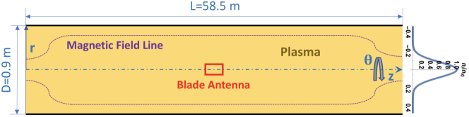
where and are the radius and length of the chamber, respectively; moreover, all field components must be regular on axis. The computational domain is shown in Fig. 2 with employed coordinate system , uniform equilibrium magnetic field with ending throats, normalized radial density profile , and the central location of blade antenna. The axial density profile is uniform. The radius of the chamber is m, while the length varies from m for uniform field to other values depending on field geometry. Other conditions include ion species of deuterium, electron temperature of eV, and blade antenna of m and m.
III Computed wave field
III.1 Uniform equilibrium field with ending throats
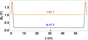
Two configurations of uniform equilibrium field with ending throats are illustrated in Fig. 3. The ending throats are constructed by , an elevated function with period length of m. The strengths of in-between equilibrium field are set to be T and T, and the corresponding depths of magnetic throats are and , respectively. Different depths are chosen to see the effect of ending throat on wave field propagation and thereby gap eigenmode formation. The field strength between ending throats also determines the collisional damping rate and resulted decay length of Alfvénic mode, through : stronger field leads to longer decay length.Chang:2014aa ; Braginskii:1965aa To compare the solved wave field in the same frequency range, and are chosen for T and T respectively, which gives the same phase velocity of Alfvénic waves through . Moreover, the radial density profile of is configured to shrink most plasma within m for weakening the interference of radial wall.
Computed results are shown in Fig. 4 and Fig. 5 for T and T respectively, including the typical wave field structure in radial and axial directions for both single and multiple frequencies. The radial profiles of real and imaginary components of in Fig. 4(a) and Fig. 5(a) show a short decay length, as expected from the steep radial density profile employed. The radial variations of magnitude at different axial locations shown in Fig. 4(b) and Fig. 5(b) illustrate the effect of magnetic throat on wave field structure: radial wave structure narrows and peaks when approaching the strong magnetic throat. These smooth radial profiles of wave field also imply the absence of continuum damping resonance for Alfvénic waves, which is beneficial for gap eigenmode formation.
Comparing Fig. 4(c) with Fig. 5(c), one could see that the axial variation of for T shows a shorter decay length than that for T, and as a result has a much stronger magnitude near the driving antenna than the latter. Shorter decay length leads to more wave energy deposited near the antenna, and bigger depth of magnetic throat results in relatively stronger wave energy accumulation near the ending throat, as shown in Fig. 4(d) and Fig. 5(d), which is another interesting effect of magnetic throat on Alfvénic waves.
The dispersion relations of solved wave field are given in Fig. 6(a), where the simple relation of for shear Alfvénic mode in a slab geometry is also overlaid. The numerical data are obtained by running the EMS for various driving frequencies, selecting the azimuthal component of the plasma response, and calculating the dominant axial wavenumber of this component via Fourier decomposition. The appeared wiggles in the dispersion curve for T are caused by reflections from endplates, which can be smoothed when the plasma cylinder is made much longer (for example m). The wave field for T has much shorter decay length thus weaker reflections, and the dispersion curve is less wiggled. However, overall, higher field strength gives better agreement with the analytical curve due to much longer decay length. This agreement is also confirmed by the contour plot of Fig. 5(d), as illustrated in Fig. 6(b). The distance between wave front and the near endplate, which stands for the wave length, decreases when the frequency is increased and exhibits a hyperbolic shape. Recalling the analytical dispersion relation of (equivalent to ), we plot this relation directly using on-axis conditions and overlay the obtained analytical curves with the contour plot and find that they agree quite well. Please note that the lower branch of green line is a direct visualization of function in an equivalent form of , because is proportional to coordinate labelling the distance between wavefront and the left end of machine ( m), and the upper branch of green line is a mirrored result regarding the location of antenna (red line).
III.2 Periodic equilibrium field with local defect
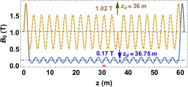
Following the similar strategy as utilized in previous studies,Chang:2013aa ; Chang:2014aa ; Chang:2016aa ; Chang:2018aa a local defect is introduced to the otherwise perfect periodic system, as shown in Fig. 7. The magnetic ripples between ending throats are constructed by T and T with the defect located at m and m, respectively. This defect configuration corresponds to the boundary condition of and produces odd-parity gap eigenmode, phrasing the parity of real and imaginary components of across the defect location.Chang:2013aa ; Chang:2014aa The other defect configuration for was also conducted and even-parity gap eigenmode was obtained with similar features as shown in Fig. 8.
The formed AGEs are shown in Fig. 8 for both and spaces. Here the effective collisionality (sum of original Coulomb collisions and electron Landau damping) has been decreased by a factor of for clear resonance peak observation. The eigenmode strength drops and width broadens as the collisionality is increased, but is still clearly visible even at the highest collision frequency, as observed before.Chang:2013aa The strongest AGEs are mG ( kHz, m, m) for T and mG ( kHz, m, m) for T. These are in order of and to the equilibrium field, respectively, making them easily observable in experiment.Zhang:2008aa Relatively the resonance peak in Fig. 8() is much more clear than that in Fig. 8(), which can be attributed to the higher field strength that yields longer decay length of Alfvénic waves in Fig. 5() than in Fig. 4().
IV Gap eigenmode dependence
IV.1 Number of magnetic ripple
Because the machine length around m and ripple depth of are costly and challenging to implement in experiment, it is highly desirable to investigate the gap eigenmode dependence on the number () and depth () of magnetic ripples. First, we gradually cut off the ripples left to the antenna, and run EMS for shortened plasma cylinder with all other conditions unchanged. Figure. 9 shows the axial variations of strongest AGE for three typical values of : , , . It can be seen that the gap eigenmode remains nearly the same when is reduced from (Fig. 7) to but becomes a little stronger for . However, the wavelength of AGE is always twice the system’s period, which is consistent with Bragg’s law,Kittel:1996aa and the magnitude always peaks at the defect location.
IV.2 Depth of magnetic ripple
Then we keep and vary from to . Figure. 10 shows the resulted dependence of strongest AGE for three typical values of : , , . It seems that there exists a certain value of depth, for which the eigenmode magnitude is maximum, for example around . More importantly, an upward frequency shift can be seen clearly as the depth of magnetic ripple drops, agreeing with a previous observation.Chang:2016aa Although detailed physical explanation has not yet been given, it is consistent with a recent finding that the whole spectral gap moves to higher frequency region as the depth is reduced.Chang:2018ab Recalling that this modulation depth is proportional to the width of spectral gap (),Zhang:2008aa ; Chang:2013aa ; Chang:2014aa this seems be a flute-like effect that the resonant cavity (spectral gap) shrinks so that the gap eigenmode frequency grows, similar to the tone tuning of a flute by shortening the resonant air column.
Therefore, it suggests that a linear plasma machine with magnetic ripples (or length of m) and modulation depth of is enough and best for the AGE observation.
V Discussion and summary
For experimental implementation of this AGE, there are four possible issues to concern: (i) the dissipative processes in the plasma will not destroy the gap-mode resonance (e. g. through varying electron temperature and plasma radius), (ii) there should be an axial slot in the conducting ring if employed as a local defect to prevent the formation of induced azimuthal current, (iii) the radial density profile if controllable does not yield continuum damping resonance of Alfvénic mode, and (iv) the range of frequency scan need be broad enough to cover the possible frequency shift when varying the depth of magnetic ripples. However, there is no visible fundamental barrier that is unsolvable in experiment, and given that the strength of formed AGE can be in order of to the equilibrium field strength, this observation is very promising referring to the diagnostic results in Zhang:2008aa . The effect of this gap eigenmode on particle transport is that once driven to large amplitude the mode can change the particle orbit of motion, through resonances between wave phase velocity and orbital frequencies, and eventually change the transport rate.Berk:1996aa ; Heeter:2000aa ; Collins:2016aa ; Qiu:2018aa Unfortunately, quantitive calculations using measured mode amplitudes underestimate the observed fast-ion transport at present, and detailed identification of nonlinear transport mechanism is immature in experiment.Heidbrink:2008aa This paper is critical for the design of a linear low-temperature plasma device with remarkable diagnostic resolutions in both space and time, which aims to study the interaction physics between AGE and energetic particles and is believed to be capable of improving our understanding of the involved particle transport mechanism significantly.
In summary, the present work computes Alfvénic waves propagating in a linear plasma ended with magnetic throats, which are designed to confine the axial movement of charged particles. Once confined the energetic ions can interact with AGE many times as happened in toroidal fusion plasmas. The radial and axial variations of wave field for uniform equilibrium field between magnetic throats are presented, for both single and multiple driving frequencies, showing a robust structure which is free of continuum damping resonance and agrees well with shear Alfvénic branch. The effects of magnetic throat on Alfvénic waves include narrowing radial mode structure, enhancing mode strength, and accumulating wave energy. For periodic equilibrium field with local defect, AGE is clearly formed inside spectral gap. It is a standing wave localized around the defect location and has wavelength twice the system’s period, consistent with Bragg’s law. This mode behaves insensitive to the reduction of magnetic ripples from to , but experiences an upward frequency shift when the depth of magnetic mirrors drops from to . The latter may be caused by a flute-like effect that the shrinking resonant cavity (namely spectral gap) forces the mode frequency to increase, similar to the upward tone tuning of a flute when the air column is shortened. This work is of great practical interest for designing a linear plasma machine to form AGE and further study its interaction with confined energetic ions, together with the nonlinear behavior and turbulence of Alfvénic waves and other relevant frontiers of physics.
Acknowledgements.
Inspiring and helpful discussions with Ran Chen and Ming Xu are appreciated. This work is supported by various funding sources: National Natural Science Foundation of China (11405271), China Postdoctoral Science Foundation (2017M612901), Chongqing Science and Technology Commission (cstc2017jcyjAX0047), Chongqing Postdoctoral Special Foundation (Xm2017109), Fundamental Research Funds for Central Universities (YJ201796), Pre-research of Key Laboratory Fund for Equipment (61422070306), and Laboratory of Advanced Space Propulsion (LabASP-2017-10).References
References
- [1] H. H. Duong, W. W. Heidbrink, E. J. Strait, T. W. Petrie, R. Lee, R. A. Moyer, and J. G. Watkins. Loss of energetic beam ions during tae instabilities. Nuclear Fusion, 33(5):749, 1993.
- [2] R. B. White, E. Fredrickson, D. Darrow, M. Zarnstorff, R. Wilson, S. Zweben, K. Hill, Yang Chen, and Guoyong Fu. Toroidal Alfvén eigenmode-induced ripple trapping. Physics of Plasmas, 2(8):2871, 1995.
- [3] K. L. Wong. A review of Alfvén eigenmode observations in toroidal plasmas. Plasma Physics and Controlled Fusion, 41(1):R1, 1999.
- [4] B. N. Breizman and S. E. Sharapov. Major minority: energetic particles in fusion plasmas. Plasma Physics and Controlled Fusion, 53(5):054001, 2011.
- [5] W. W. Heidbrink. Basic physics of alfvén instabilities driven by energetic particles in toroidally confined plasmas. Physics of Plasmas, 15(5):055501, 2008.
- [6] C. Z. Cheng L. Chen and M. S. Chance. High-n ideal and resistive shear Alfvén waves in tokamaks. Annals of Physics, 161(1):21, 1985.
- [7] A. Fasoli, J. B. Lister, S. Sharapov, D. Borba, N. Deliyanakis, C. Gormezano, J. Jacquinot, A. Jaun, H. A. Holties, G. T. A. Huysmans, W. Kerner, J.-M. Moret, and L. Villard. Observation of multiple kinetic alfvén eigenmodes. Physical Review Letters, 76:1067–1070, Feb 1996.
- [8] J. W. (Lord Rayleigh) Strutt. On the maintenance of vibrations by forces of double frequency, and on the propagation of waves through a medium endowed with periodic structure. Philosophical Magazine, 24:145, 1887.
- [9] N. F. Mott. Conduction in non-crystalline systems .i. localized electronic states in disordered systems. Philosophical Magazine, 17(150):1259, 1968.
- [10] A. Figotin and A. Klein. Localized classical waves created by defects. Journal of Statistical Physics, 86:165, 1997.
- [11] C. Kittel. Introduction to Solid State Physics. Wiley, New York, 7th edition, 1996.
- [12] ITER Physics Expert Group on Energetic Particle, Heating, and Current Drive. Chapter 5: Physics of energetic ions. Nuclear Fusion, 39(12):2471, 1999.
- [13] A. Fasoli, C. Gormenzano, H.L. Berk, B. Breizman, S. Briguglio, D.S. Darrow, N. Gorelenkov, W.W. Heidbrink, A. Jaun, S.V. Konovalov, R. Nazikian, J.-M. Noterdaeme, S. Sharapov, K. Shinohara, D. Testa, K. Tobita, Y. Todo, G. Vlad, and F. Zonca. Chapter 5: Physics of energetic ions. Nuclear Fusion, 47(6):S264, 2007.
- [14] W. Gekelman, H. Pfister, Z. Lucky, J. Bamber, D. Leneman, and J. Maggs. Design, construction, and properties of the large plasma research device - the lapd at ucla. Review of Scientific Instruments, 62(12):2875, 1991.
- [15] B. D. Blackwell, J. F. Caneses, C. M. Samuell, J. Wach, J. Howard, and C. Corr. Design and characterization of the magnetized plasma interaction experiment (magpie): a new source for plasma–material interaction studies. Plasma Sources Science and Technology, 21(5):055033, 2012.
- [16] J. Rapp, T.M. Biewer, T.S. Bigelow, J.F. Caneses, J.B.O. Caughman, S.J. Diem, R.H. Goulding, R.C. Isler, A. Lumsdaine, C.J. Beers, T. Bjorholm, C. Bradley, J.M. Canik, D. Donovan, R.C. Duckworth, R.J. Ellis, V. Graves, D. Giuliano, D.L. Green, D.L. Hillis, R.H. Howard, N. Kafle, Y. Katoh, A. Lasa, T. Lessard, E. H. Martin, S.J. Meitner, G.-N. Luo, W.D. McGinnis, L.W. Owen, H.B. Ray, G.C. Shaw, M. Showers, V. Varma, and the MPEX team. Developing the science and technology for the material plasma exposure experiment. Nuclear Fusion, 57(11):116001, 2017.
- [17] Y. Zhang, W. W. Heidbrink, H. Boehmer, R. McWilliams, G. Chen, B. N. Breizman, S. Vincena, T. Carter, D. Leneman, W. Gekelman, P. Pribyl, and B. Brugman. Spectral gap of shear Alfvén waves in a periodic array of magnetic mirrors. Physics of Plasmas, 15(1):012103, 2008.
- [18] L. Chang, B. N. Breizman, and M. J. Hole. Gap eigenmode of radially localized helicon waves in a periodic structure. Plasma Physics and Controlled Fusion, 55(2):025003, 2013.
- [19] L. Chang. The impact of magnetic geometry on wave modes in cylindrical plasmas. PhD thesis, Australian National University, Canberra, 2014.
- [20] L. Chang, N. Hu, and J. Y. Yao. Influence of number and depth of magnetic mirror on alfv?enic influence of number and depth of magnetic mirror on alfvenic gap eigenmode. Chin. Phys. B, 25(10):105204, 2016.
- [21] L. Chang, Y. H. Li, Y. Wu, H. J. Zhang, W. M. Wang, and H. M. Song. Dynamic control of defective gap mode through defect location. Plasma Science and Technology, 18(1):1–5, January 2016.
- [22] L. Chang. Preliminary computation of the gap eigenmode of shear alfven waves on lapd. accepted by Chinese Physics B on 16 October 2018.
- [23] R. Chen. private communication, Institute of Plasma Physics (CAS), 2017.
- [24] Z. H. Wang. private communication, Southwestern Institute of Physics, 2017.
- [25] Y. K. Peng. private communication, Oak Ridge National Laboratory, 2017.
- [26] J. P. Freidberg. Plasma Physics and Fusion Energy. Cambridge University Press, 2007.
- [27] J. Wesson. Tokamaks. Oxford University Press, fourth edition, 2011.
- [28] L. A. Artsimovich. Tokamak devices. Nuclear Fusion, 12(2):215, 1972.
- [29] W. W. Heidbrink. Beam-driven chirping instability in diii-d. Plasma Physics and Controlled Fusion, 37(9):937, 1995.
- [30] S. D. Pinches, H. L. Berk, D. N. Borba, B. N. Breizman, S. Briguglio, A. Fasoli, G. Fogaccia, M. P. Gryaznevich, V. Kiptily, M. J. Mantsinen, S. E. Sharapov, D. Testa, R. G. L. Vann, G. Vlad, F. Zonca, and JET-EFDA Contributors. The role of energetic particles in fusion plasmas. Plasma Physics and Controlled Fusion, 46(12B):B187, 2004.
- [31] J. Zhu, Z.W. Ma, and G.Y. Fu. Nonlinear frequency chirping of toroidal alfv n eigenmodes in tokamak plasmas. Nuclear Fusion, 54(12):123020, 2014.
- [32] G. Chen, A. V. Arefiev, R. D. Bengtson, B. N. Breizman, C. A. Lee, and L. L. Raja. Resonant power absorption in helicon plasma sources. Physics of Plasmas, 13(12):123507, 2006.
- [33] C. A. Lee, G. Chen, A. V. Arefiev, R. D. Bengtson, and B. N. Breizman. Measurements and modeling of radio frequency field structures in a helicon plasma. Physics of Plasmas, 18(1):013501, 2011.
- [34] L. Chang, M. J. Hole, J. F. Caneses, G. Chen, B. D. Blackwell, and C. S. Corr. Wave modeling in a cylindrical non-uniform helicon discharge. Physics of Plasmas, 19(8):083511, 2012.
- [35] V. L. Ginzburg. The Propagation of Electromagnetic Waves in Plasmas. Number p84. Pergamon, Oxford, 1964.
- [36] S. I. Braginskii. Transport processes in a plasma. Reviews of Plasma Physics, 1:302, 1965.
- [37] L. Chang. On the limit of spectral gap formation via bragg’s reflection. Physics of Plasmas, submitted to Physics of Plasmas on 12 September 2018.
- [38] H. L. Berk, B. N. Breizman, and M. Pekker. Nonlinear dynamics of a driven mode near marginal stability. Physical Review Letters, 76(8):1256–1259, 1996.
- [39] R. F. Heeter, A. F. Fasoli, and S. E. Sharapov. Chaotic regime of alfvén eigenmode wave-particle interaction. Physical Review Letters, 85:3177–3180, Oct 2000.
- [40] C. S. Collins, W. W. Heidbrink, M. E. Austin, G. J. Kramer, D. C. Pace, C. C. Petty, L. Stagner, M. A. Van Zeeland, R. B. White, and Y. B. Zhu. Observation of critical-gradient behavior in alfvén-eigenmode-induced fast-ion transport. Physical Review Letters, 116:095001, Feb 2016.
- [41] Z. Qiu, L. Chen, F. Zonca, and W. Chen. Nonlinear decay and plasma heating by a toroidal alfvén eigenmode. Physical Review Letters, 120:135001, Mar 2018.