Device-to-Device Communications Enabled Multicast Scheduling with the Multi-Level Codebook in mmWave Small Cells
Abstract
With the exponential growth of mobile data, there are increasing interests to deploy small cells in millimeter wave (mmWave) bands to underlay the conventional homogeneous macrocell network as well as in exploiting device-to-device (D2D) communications to improve the efficiency of the multicast service that supports content-based mobile applications. To compensate for high propagation loss in the mmWave band, high-gain directional antennas have to be employed, while it is critical to optimize multicast service in order to improve the network performance. In this paper, an efficient multicast scheduling scheme is proposed for small cells in the mmWave band, called MD2D, where both D2D communications in close proximity and multi-level antenna codebook are utilized. Specifically, a user partition and multicast path planning algorithm is proposed to partition the users in the multicast group into subsets and to determine the transmission node for each subset, so as to achieve optimal utilization of D2D communications and multi-level antenna codebook. Then a multicast scheduling algorithm schedules the transmission for each subset. Furthermore, in order to optimize the network performance, the optimal choice of user partition thresholds is analyzed. Performance evaluation demonstrate that the MD2D achieves the best performance, in terms of network throughput and energy efficiency, compared with other existing schemes. MD2D improves the network throughput compared with the second-best scheme by about 27%.
Index Terms:
Millimeter wave communication, device-to-device communication, small cells, multicast service, directional antenna, multi-level codebookI Introduction
Mobile traffic demands are explosively increasing over the past decade [1]. In order to improve mobile network capacity accordingly, small cells underlying the macrocell have been proposed and received much attention, which is referred to as heterogeneous cellular networks (HCNs) [2]. By utilizing the millimeter wave (mmWave) bands, and by a dense deployment of small cells [2, 3], HCN can significantly improve the network capacity with less interference, compared to a conventional HCN deployment. The mmWave bands, such as the 28 GHz band, the 60 GHz band, and the E-band, have abundant spectrum. Consequently, multi-Gbps communication services can be supported [4]. Moreover, rapid development in complementary metal-oxide-semiconductor technology for radio frequency integrated circuits paves the way for electronic products in the mmWave band [5]. Several standards have been defined for indoor wireless personal area networks (WPAN) and wireless local area networks (WLAN), such as IEEE 802.15.3c [6], IEEE 802.11ad [7], and IEEE 802.11ay [8].
With higher carrier frequency, mmWave communications suffer from higher propagation loss. Thus, directional antennas need to be adopted at both transmitter and receiver to form directional high-gain beams in order to compensate the high propagation loss [9, 10, 11, 12]. It is well-known that wide beams have low antenna gains and can only support low transmission rates, while narrow beams have high antenna gains and can support high transmission rates. With the aid of the multi-level antenna codebook, therefore, transmitters can use wide beams to communicate with multiple low-rate receivers, and use narrow beams to communicate at a high transmission rate. Hence, by optimizing the beam selection in a multi-level antenna codebook, the flexibility of directional beams can be utilized to enhance the achievable network throughput.
It is found that a small amount of popular content occupy the majority of requests in content downloading, and the content popularity in mobile networks is found to obey the Zipf’s law [13]. In multicast service, the access point (AP) provides multiple users within a multicast group with the same data [14, 15]. To serve more users simultaneously, wider beams are preferred. But wider beams with lower antenna gain can only support lower transmission rate, which degrades multicast efficiency. Thus, dividing the multicast group into multiple subsets becomes necessary. On the other hand, in the user-intensive region, where the multicast service is usually applied, two user devices will be probably located near to each other. In this case, device-to-device (D2D) communications can be enabled for improving multicast efficiency, owing to better channel conditions [16]. For the multicast traffic, users already with the multicast content can use the D2D communications to forward the content to users nearby. Thus, D2D communications usually have shorter distance, and thus the propagation loss is less. Consequently, higher transmission rate can be obtained, and thus less transmission time is needed. Thus, network throughput can be increased. With less time needed to accommodate the multicast demands, lower energy consumption can be achieved if the transmission power is fixed. Therefore, the energy efficiency can be increased.
Against the above background, in this paper, we investigate the problem of optimal multicast scheduling in mmWave small cells underlaid by D2D communications. This problem is challenging because to serve users efficiently, users in the multicast group must be partitioned optimally into subsets and beams must be selected optimally to serve users in each subset. Moreover, user device with the multicast traffic must be capable of serving other subsets efficiently by exploiting better D2D channels. The D2D communication here is for multicast transmission, and “D2D” here means “one device to multiple devices using directional beams”, which is very different from previous works. To obtain a practical solution, we develop an efficient multicast scheduling scheme, called MD2D, where appropriate beams are selected to serve users efficiently in each multicast transmission, while D2D communications are utilized to improve multicast efficiency. The contribution is three-fold as summarized below.
-
•
We formulate the problem of the optimal multicast scheduling with D2D communications and beam selection in a multi-level codebook considered into a mixed integer nonlinear program that minimizes the total multicast transmission time, by efficient multicast group partition, beam selection, and D2D communication utilization.
-
•
To obtain a practical solution to this challenging problem, an efficient multicast scheduling scheme is proposed, called MD2D, where two algorithms are proposed, user partition and multicast path planning, and multicast scheduling. The first algorithm appropriately partitions the users in the multicast group into subsets and determines the transmission node for each subset, while the second one schedules the transmission for each subset efficiently.
-
•
We further investigate the optimal selection of user partition thresholds to optimize the achievable network performance. Extensive evaluations under various system settings show our proposed MD2D achieves the best performance, in network throughput and energy efficiency, compared with other schemes.
The structure of this paper is as follows. Section II reviews the related work on the media access control (MAC) protocols for mmWave small cells. Section III illustrates the system model and the basic idea of our MD2D. Section IV formulates the optimal multicast scheduling problem with D2D communications, multicast group partition and beam selection in a multi-level codebook. Section V is entirely devoted to our proposed multicast scheduling scheme, namely, MD2D. Section VI evaluates the performance of our MD2D scheme, in terms of network throughput and energy consumption, using there existing schemes as the benchmarks. Section VII gives the conclusion.
II Related Work
There exist some related works on directional MAC protocols for WPANs and WLANs in the mmWave band [17, 18, 19, 20, 21]. In WPANs and WLANs, time division multiple access (TDMA) protocol is traditionally adopted [22, 6]. Cai et al. [18] derived the conditions of exclusive region that concurrent transmission always outperforms TDMA. In an indoor IEEE 802.15.3c WPAN, the work of [17] proposed a concurrent transmission scheduling algorithm to maximize the number of flows with the quality of service requirement for each flow satisfied. In [21], a multi-hop concurrent transmission scheme is developed to overcome the link outage problem and to enhance flow throughput. For TDMA based protocols, an unfair medium time allocation problem exists for individual users under bursty data traffic [23].
There also exist some centralized protocols proposed for WPANs or WLANs in the mmWave band [24, 25, 23, 26]. In [25], a multihop-relay based directional MAC (MRDMAC) protocol is proposed, where the PNC applies a weighted round robin scheduling to overcome the deafness problem. MRDMAC utilized multi-hop relaying to overcome blockage. Son et al. [23] proposed a frame based directional MAC protocol (FDMAC). The core of this FDMAC is the greedy coloring algorithm, which utilizes concurrent transmissions to improve the network throughput. Niu et al. [27] proposed a blockage-robust and efficient directional MAC (BRDMAC) protocol to overcome the blockage problem by two-hop relaying. Recently, Niu et al. [28] proposed a joint transmission scheduling protocol for the radio access and backhaul of small cells in mmWave band, called D2DMAC. In D2DMAC, a path selection criterion is proposed to exploit D2D transmissions when performance improvement is available. Zhang et al. [29] investigate user association and power allocation in mmWave-based ultra dense networks with attention to load balance constraints, energy harvesting by base stations, user quality of service requirements, energy efficiency, and cross-tier interference limits. To solve the joint user association and power optimization problem, they proposed an iterative gradient user association and power allocation algorithm to achieve an optimal point.
In terms of multicast communication, there also exist a few works on MAC protocols for WPANs and WLANs in the mmWave band [15, 30]. Naribole et al. [15] implemented a technique called scalable directional multicast (SDM) to train the AP with per-beam per-client received-signal-strength-indicator measurements via partially traversing a codebook tree. Based on the training information, they proposed a scalable beam grouping algorithm to obtain the minimum multicast group data transmission time. Park et al. [30] proposed an incremental multicast grouping (IMG) scheme where the beamwidths are adaptively assigned. However, D2D communications were not enabled in this IMG.
It is clear that jointly utilizing multi-level codebook and D2D communications to maximize multicast efficiency for small cells in the mmWave band is challenging and has not been exploited in the open literature.
III System Overview
III-A System Model
In a mmWave small cell of nodes, one node is the AP and the rest are user equipments (UEs). The system time is partitioned into non-overlapping time slots of equal length. The AP synchronizes the clocks of UEs and schedules the medium access to accommodate the multicast demand. Equipped with steerable directional antennas, the AP and users generate the directional beams of different beamwidths via a multi-level codebook. We assume that a bootstrapping program is run in the system so that the AP has the network topology and the location information of UEs [31, 32, 33].
We assume the mmWave small cells are deployed underlying the macrocell to form the heterogeneous cellular network (HCN), and the small-cell APs and UEs are also equipped with omnidirectional antennas for 4G communications. Thus, the location information can also be obtained by the localization techniques in the cellular bands. Meanwhile, the transmission requests and some signaling information for mmWave small cells can be collected by the reliable 4G communication.
Because non-line-of-sight transmissions suffer from very high attenuation, mmWave communications in small cell mainly rely on line-of-sight (LOS) transmissions. Therefore, we assume that a LOS path is available for each transmission [34].
Denote the directional link from node to by . In directional beamforming, both nodes and point toward each other via a beam from an -level codebook. Assume that transmit node adopts the th beam in the th level of the codebook, which is denoted as , and the antenna gain of in the direction of is , while receive node adopts the th beam in the th level of the codebook, which is denoted by , and the antenna gain of in the direction of is . Then based on the path loss model [34], the received power at node for link is given by
| (1) |
where is the transmission power and is a constant that is proportional to ( is carrier wavelength), while is the distance between transmitter and receiver and is the path loss exponent [17]. Hence the received signal to noise ratio (SNR) of link is calculated according to
| (2) |
where is the bandwidth and is the one-sided power spectra density of the link’s white Gaussian noise [17]. Considering the reduction of multipath effect for directional mmWave links [25], the achievable data rate of link can be estimated based on Shannon’s channel capacity as
| (3) |
where denotes the efficiency of the transceiver [17].

(a) Time-line illustration of MD2D
(b) Network topology and MD2D operation
III-B Problem Overview
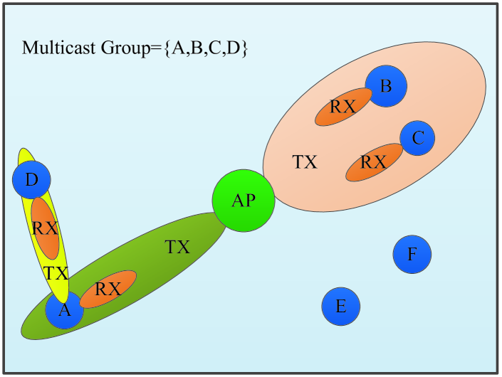
We consider the multicast service transmitted from the AP to a multicast group. To improve multicast efficiency, appropriate beams should be selected from the multi-level codebook for each multicast transmission. How to select appropriate beams is illustrated in Section V-A. Besides, users should be able to receive the multicast service from nearby users through D2D communications. To illustrate our MD2D scheme, which exploits both D2D transmissions and multi-level codebook, we use the simple example depicted in Fig. 1, which is a small cell of six users, with the multicast group consisting of users A to D.
Fig. 1 (a) depicts the time-line illustration of this example. In the system, time is divided into a sequence of non-overlapping frames [23]. Each frame has two periods, multicast scheduling period and multicast transmission period. In the scheduling period, the AP first obtains the multicast traffic and the information of the associated multicast group from the network layer, which needs time ; next the AP computes a schedule required to complete the multicast service, which needs time ; then AP pushes the schedule to the users in sequence, which needs time . In the transmission period, all the nodes in the multicast group begin transmissions according to the schedule until the multicast traffic is distributed to all the users in the group. As illustrated in Fig. 1 (a), a multicast transmission period is naturally divided into multiple phases according to the schedule, and in each phase, the multicast transmission occupies several time slots.
Fig. 1 (b) illustrates the network topology of this simple example. To serve this multicast group efficiently, the multicast group can be partitioned into three subsets, namely, user A, users B and C, and user D. Since users B and C are located sufficiently close with a very small angle difference, the AP can serve them with a wide beam simultaneously. By contrast, since user D and user A span a large angle, serving them simultaneously with a wide beam will lead to low transmission rate and, consequently, requires many more time slots. Instead, the AP may serve user A with a narrow beam, and then by exploiting the close proximity of users A and D, the AP can let user A to serve user D via the D2D communication.
Thus, the schedule as shown in Fig. 1 (a) is obtained, which consists of three multicast transmission phases in a frame. In the first phase, the AP directs its narrowest beam towards user A to achieve the highest transmission rate, as illustrated in Fig. 1 (b), which occupies three time slots. In the second phase, AP serves users B and C simultaneously with a wide beam, which occupies three time slots. Finally, user A serves user D with the narrowest beam to achieve highest transmission rate in the third phase. Because users A and D are very close, this D2D based third phase only occupies two time slots. Thus, a total of eight time slots are needed to serve the multicast group. By contrast, if the AP serves the four users sequentially with the narrowest beams, a total of twelve time slots are needed.
From this simple example, we can clearly observe that there are two key problems to solve in order to maximize multicast efficiency. The first one is how to partition the multicast group into subsets and serve each subset via an appropriate beam to achieve high multicast efficiency. The second one is how to effectively utilize D2D communications by exploiting the physical proximity of devices to further improve multicast efficiency as much as possible.
IV Problem Formulation
The set of users in the multicast group is denoted by and partition into subsets, i.e., . Note that the users in each subset receive multicast service simultaneously. We denote the th user in the th subset by . Since is at least 1, . The traffic demand for the multicast group is denoted by . The schedule for the multicast transmission period of a frame contains phases, and each phase lasts several consecutive time slots.
For each phase, we define the size vector to indicate whether the subsets of the multicast group are scheduled in the th phase, where . Specifically, let the th element of be denoted by , where . If is scheduled in the th phase, ; otherwise, . We denote the transmit node for the subset by . Since D2D communication is enabled, may be the AP or a user with the multicast data. When is a user with the multicast data, we denote the multicast subset that belongs to by , i.e., denotes the subset number of . For the user , the achievable transmission rate provided by is as given in (3), which is rewritten here
| (4) |
where again denotes the transmit beam of and is the receive beam of . We denote the set of beams, i.e., the codebook with levels, by . Therefore, . We further denote the required transmission rate to serve the users in simultaneously by . We denote the number of time slots scheduled for the th phase by , and the time slot duration is .
To maximize the multicast efficiency or throughput, the transmission schedule should accommodate the multicast demand of all the users with a minimum number of time slots. Therefore, the objective function to be minimized is simply
| (5) |
Next we analyze the system constraints of this multicast transmission optimization problem.
First, each multicast group is partitioned into several subsets, which is expressed as the following two constraints
| (6) | ||||
| (7) |
Second, since is a binary variable, we have the constraint
| (8) |
Third, to reduce beamforming overhead and system complexity, we restrict to the case that the multicast transmission for each subset is only scheduled once in one frame of the schedule. Thus, we have
| (9) |
Fourth, to serve the users in each subset simultaneously, the required transmission rate must meet the condition
| (10) |
where is given by (4) with the constraint
| (11) |
Fifth, the schedule must meet the multicast demand, and therefore we must have
| (12) |
Lastly, to be able to exploit D2D communications, the transmit node of each subset should obtain the multicast data first. Thus, if a subset has a user that transmits multicast data to another subset, then the multicast transmission to this subset should be scheduled prior to the D2D based multicast transmission to the other subset. This constraint can be expressed as
| (13) |
Thus, the optimal multicast scheduling problem (P1) can be expressed as follows
| (14) |
Note that constraints (10) and (12) are nonlinear, and there exists set partitioning operation in constraint (6). Thus the problem is a mixed integer nonlinear programming, where are binary variables, are integer variables and is an integer variable, while and are discrete variables. This problem is more complex than the NP-complete 0-1 Knapsack problem [17, 35]. The optimal solution can be obtained via the exhaustive search, which has high computational complexity, and cannot be applied in practice.
V Proposed Multicast Scheduling Scheme
As stated previously, there are two key mechanisms to improve multicast efficiency. First, the potential of multi-level codebook should be unleashed. Wide beams are able to cover larger angle range and may serve more users simultaneously. However, wide beams have low antenna gains, and achievable transmission rates may be low. By contrast, narrow beams have high antenna gains and are able to support high transmission rates. But narrow beams have limited coverage in angle range and may not be able to serve many users simultaneously. Second, the advantages of D2D communications in physical proximity should be reaped. If the users are located sufficiently close, multicast transmission using a wide beam may be more efficient. Clearly, optimizing the network performance based on these two mechanisms is a complex problem, which requires elaborate design for user partition, multicast path planning and beam selection for multicast transmission. To reduce complexity and achieve practical solutions, we propose the heuristic multicast scheduling scheme, MD2D, for the optimization problem (P1). Specifically, we first propose a user-clustering and multicast-path-planning algorithm to partition the multicast group into appropriate subsets and to decide the multicast transmission paths for the multicast group, which is required by constraints (6) and (7).
V-A User Partition and Multicast Path Planning
We start from the AP to find the nearest user subset. Users that are located very close to each other and span a limited angle range will be put into a subset to be served simultaneously. In this way, we can realize the potential of multi-level codebook, and use wide beams to serve more users. We continue to expand the set of the already allocated subsets including the AP by finding the possible user subset nearby. If such a newly selected subset is very close to one of the allocated subsets, then we enable the D2D communications between these two subsets to serve this new subset more efficiently. Of course, the multicast transmission to this new subset should be scheduled behind the transmission to the allocated subset. In this way, the advantages of D2D communications are exploited to enhance multicast efficiency. In other words, the objective function in problem (P1) can be optimized via D2D communications.
Let us denote the AP in the small cell as and the subset of users that the algorithm allocates in the th iteration by . We also denote the set of the subsets that have been allocated and thus are able to serve other unallocated users by . Since the AP has the multicast data to serve users, it can be regarded as a subset that has been allocated, and thus is initialized to . The allocated multicast transmission path from allocated subset to the new subset in the th iteration is denoted by . For each subset with , we define the polar coordinates of user relative to the center of by . For each subset , we denote its transmit node by , and the beam selected for to serve is denoted by . We assume that all the users in point to with the narrowest or finest receive beams. The radius threshold and angle threshold for user partition are denoted by and , respectively.
The pseudo-code of this user partition and multicast path planning is listed in Algorithm 1. Starting from line 3, it iteratively partitions the users in into subsets and schedules the multicast transmission for each subset until all the users are scheduled. Specifically, in the th iteration, we first find a user with the shortest distance from a subset in lines 5–8. Then we allocate the users that are close to this user into the subset in lines 9–15. We measure the closeness in terms of distance and angle with respect to the reference subset identified in lines 5–8. The angle that the current users span is denoted by , as indicated in lines 10–12. As shown in line 13, the users selected should be located not far from the reference radius by a threshold , and the angle that the current users in the subset span after the candidate user is added should be no more than a threshold . If the candidate user meets these two conditions, it is added into and also removed from , as shown in lines 14–15. In line 16, the newly allocated subset is added to and the multicast transmission from to is recorded by . Lines 17–21 determine the transmit node and select beam for . We first obtain the maximum achievable rate and corresponding beam for each user in to serve , denoted by and . Then, we select the user in with the highest maximum achievable rate as the transmit node for , and the corresponding beam is recorded, which is the appropriate beam we referred to before. The algorithm is completed in line 22 by returning , , and the selected transmit node and beam for each subset.
The outer loop of lines 3–21 has iterations. Each of the three inner loops, lines 5–7, lines 9–15 and lines 17–19, has at most iterations. Moreover, the operations inside each inner loop impose at most the complexity on the order of . Therefore, the worst-case computational complexity of Algorithm 1 is on the order of .
V-B Multicast Scheduling Algorithm
The proposed multicast scheduling algorithm iteratively allocates the multicast transmission for each subset into each phase until all the subsets are scheduled. We will denote the scheduled multicast transmission in the th phase by . The pseudo-code of this multicast scheduling is given in Algorithm 2. Note that to meet the requirement of constraint (13), only the user with the multicast data is able to serve other users. Thus, if user in subset is the transmit node for subset , the multicast transmission to must be scheduled before the transmission to . In Algorithm 1, we obtain after , and this order naturally meets constraint (13). Therefore, we can simply schedule the transmissions to the subsets one by one by following the same order as recorded by Algorithm 1, as indicated in lines 4–6 of Algorithm 2, which select the subset for the th phase. The transmit node and beam determined by Algorithm 1 for this subset are then used for the multicast transmission to this subset in the th phase, as indicated in lines 7–8. As shown in line 7, there is only one multicast transmission for each phase, which is required by constraint (9). The scheduling results for all the phases are outputted in line 9.
The computational complexity of Algorithm 2 is obviously on the order of , where , which is negligible compared with the computational complexity of Algorithm 1. Therefore, the computational complexity of our proposed multicast scheduling scheme MD2D, which consists of Algorithm 1 and Algorithm 2, is on the order of .
VI Performance Evaluation
This section evaluates our MD2D scheme. We also investigate the impact of the two thresholds in Algorithm 1, and , on the achievable system throughput, energy consumption, and energy efficiency.
VI-A Simulation Setup
In an mmWave small cell with users, the AP is located in the center of a square area and the users are uniformly and randomly distributed in the area. After the bootstrapping program, we assume the network topology and location information of nodes have been collected by the AP, and the information will be updated periodically. During each frame, due to Gbps transmission rate in the mmWave band, the signalling overhead involving D2D path planning and transmission scheduling is small, and does not have a significant impact on system performance [23]. Besides, the difference in overhead for different schemes is small, and thus we mainly consider the transmission part for performance evaluation.
We adopt the directional antenna model from IEEE 802.15.3c with a main lobe of Gaussian form in linear scale and constant level of side lobes [36]. The gain of the directional antenna in dB, denoted by , can be expressed as
| (15) |
where the angle takes the value in , is the angle of the half-power beamwidth. In the simulation, we adopt the four-level codebook, where the half-power beamwidth is equal to , , and , respectively. The parameters of the simulated mmWave small cell are summarized in Table I [27, 28]. For each experiment, we perform one hundred independent simulations and take the average of the results.
| Parameter | Symbol | Value |
|---|---|---|
| System bandwidth | W | 2160 MHz |
| Background noise | -134dBm/MHz | |
| Path loss exponent | 2 | |
| Number of users | ||
| Maximum Transmission power | dBm | |
| Time slot duration | 18 s | |
| Efficiency of the transceiver design | 0.5 | |
| Multicast data size | Gb |
We adopt the following three performance metrics.
1) Network Throughput: The achieved multicast throughput of all the users in the network, expressed as
| (16) |
2) Energy Consumption: The total energy consumption of all the multicast transmissions, given by
| (17) |
where is the transmission rate in the th phase.
3) Energy Efficiency: The ratio of the achieved network throughput over the consumed energy, which is expressed as
| (18) |
As reviewed in Section II, there exists no previous work in the existing literature that joint exploits D2D communications and multi-level codebook for improving multicast efficiency in mmWave based networks. In order to demonstrate the advantages of utilizing both D2D communications and multi-level codebook in our MD2D scheme, we compare our scheme with the following three multicast schemes.
1) FDMAC: In the FDMAC scheme, the AP sequentially transmits the multicast data to the users one by one using the finest-level beam. This is the baseline scheme which exploits neither multi-level codebook nor D2D communications [23].
2) MC: In the multi-level codebook scheme, the multicast group is divided into different subsets, and the AP selects an optimal beam from the multi-level codebook to serve each subset. In this scheme, the multi-level codebook is exploited but D2D communications are not enabled. Through comparison with the MC scheme, the advantages of using D2D communications in our scheme can be observed.
3) D2D: In the D2D multicast scheme, D2D communications are utilized to improve the system performance, similar to the MD2D. However, for this D2D-only scheme, the finest-level beam is always used for each transmission, where only one user is served. Therefore, unlike our MD2D, this scheme does not utilize the multi-level codebook. Through the comparison with the D2D scheme, the advantages of our scheme due to the multi-level codebook are demonstrated.
To evaluate our scheme under NLOS transmissions, we adopt the NLOS parameters in [34], where the path loss exponent is equal to 3.01, and the shadowing effect is also considered. In the following performance evaluation, the results under NLOS transmissions are also presented.
VI-B Impact of the User Partition Thresholds
Intuitively, the choice of the radius threshold and angle threshold in Algorithm 1 of user partition and multicast path planning will seriously impact the performance of our MD2D scheme. For the system specified in Section VI-A, Fig. 2 plots the network throughput performance achieved by our MD2D with various radius and angle threshold values.
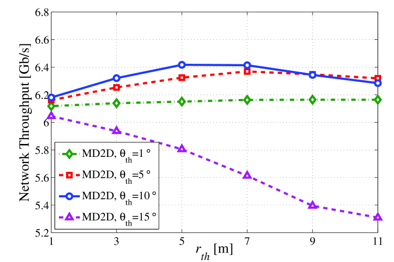
In terms of the impact of angle threshold, too small or too large will degrade the achieved NT performance metric. More specifically, with a small angle threshold of , only a small number of users located nearby can be allocated into a same subset, and MD2D will choose narrow beams to serve each subset. Consequently, the potential of the multi-level codebook is not fully exploited, and the number of transmissions increases, which degrades the network throughput. On the other hand, with a large angle threshold of , many more users will be allocated into a same subset. MD2D will serve such a subset via a wide beam, and the transmission rate will decrease. Besides, some users served in this way would be much better served via more efficient D2D communications. For this system, it can be observed that with , MD2D achieves the best performance.
In terms of the impact of radius threshold, given a too small angle threshold of , the influence of to the achieved NT performance metric is very small. By contrast, given a too large angle threshold of , increasing degrades the achieved NT performance metric seriously. With the ‘optimal’ angle threshold , MD2D with m achieves the best performance and, moreover, for between 5 m and 7 m, the network throughputs are all very good. Observe that in the case of , when is small, the network throughput increases with the radius threshold. This is because more users are allocated into a same subset, and wide beams are able to serve these subsets simultaneously, which unleashes the potential of the multi-level codebook. However, when is large, increasing degrades the performance. This is because similar to the case of too large angle threshold, too many users will be allocated into a same subset which reduces the transmission rate and, moreover, D2D communications could not be exploited fully to improve the network performance. With the angle threshold , the best choice of radius threshold is m.
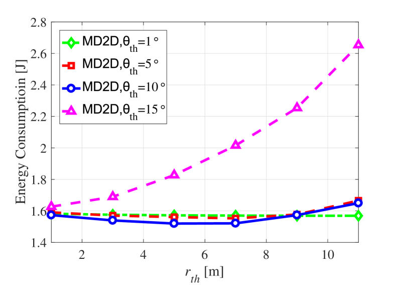
Besides, in Fig. 3, we plot the energy consumptions achieved by our MD2D with different radius thresholds and angle thresholds. We can obverse that MD2D with angle threshold and radius threshold between 5 m and 7 m consumes least energy. For this system, higher throughput means that it can finish task scheduling faster, which causes that the system consumes less energy. According to the above analysis and simulation results, with the ‘optimal’ angle threshold , MD2D with radius threshold between 5 m and 7 m, achieves the best network throughput performance. Hence, MD2D with the same threshold ought to consume least energy, which agrees with the simulation results.
For this system, it can be seen that the optimal choice of angle threshold and radius threshold is around and in the range of 5 m to 7 m. From this experiment, we may conclude that the angle threshold and radius threshold should be optimized according to the network environment, in order to maximize the achieved network throughput performance. Although the optimal threshold may be different under each case, the threshold can be selected to be optimized for the most of the cases. On the other hand, when the performance degrades too much in some cases, the system is assumed to adapt to the changes, and adjust the thresholds in our scheme.
VI-C Comparison with Other Schemes
We now compare the NT, EC and EE performance of our MD2D scheme with those of the other three schemes, i.e., FDMAC, MC and D2D. The user partition thresholds of our MD2D, and , are set to 6 m and , respectively, according to the investigation of the previous section.
VI-C1 Network Throughput
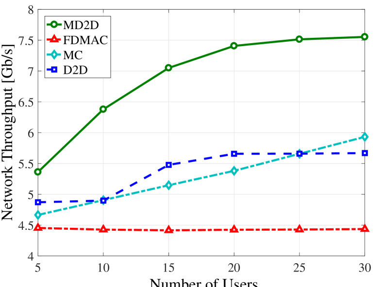
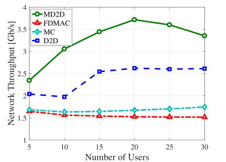
Fig. 4 compares the NT performance metrics achieved by the four schemes for different numbers of users. As expected, the FDMAC scheme attains the worst performance and its NT metric remains constant with the increase of . By contrast, the NT metric of the MC scheme increases linearly with . With the increase of users, the MC scheme can exploit the multi-level codebook more effectively. As for the D2D scheme, its NT metric is relatively low when is small. But when there are sufficient users in the network, the benefit of D2D communications becomes significant, leading to the considerable increase in the achieved NT performance. However, as increases further, its NT performance becomes saturated. The results of Fig. 4 also confirm that our MD2D scheme achieves the best performance among the four multicast schemes. For example, given , the MD2D scheme improves the network throughput by about 10% over the second-best D2D scheme, while with , our MD2D scheme outperforms the second-best MC scheme by 27%.
In Fig. 5, the network throughput comparison of our scheme and three other schemes with different number of users under NLOS transmission assumption is presented. The results show that our scheme performs best under NLOS transmission assumption. Compared with results under LOS assumption, MD2D scheme achieves lower throughput since links suffer higher propagation loss under NLOS transmission assumption.
Fig. 6 depicts the NT metrics as the functions of achieved by the four schemes. Since the is in dBm in the figure, the relationship between NT and transmission power is still consistent with Shannon law. As expected, the FDMAC scheme attains the worst performance, while our MD2D achieves the best performance. Specifically, the performance gap between our MD2D scheme and the second-best MC scheme increases from 1.5 Gb/s to 1.9 Gb/s as increases from 30 dBm to 40 dBm.
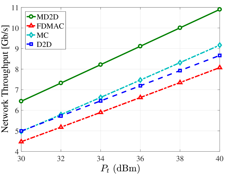
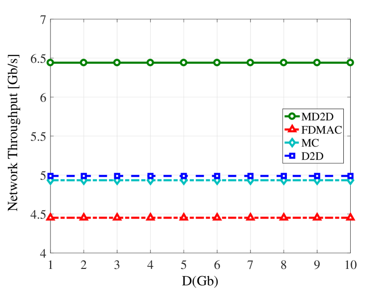
Fig. 7 compares the NT performance metrics achieved by the four schemes, given different multicast data sizes. Since the number of time slots required scales with the multicast data size, the network throughput remains constant when the multicast data size changes. Again the FDMAC scheme attains the worst performance and our MD2D achieves the best performance. The performance gap between our MD2D scheme and the second-best D2D scheme is 1.4 Gb/s.
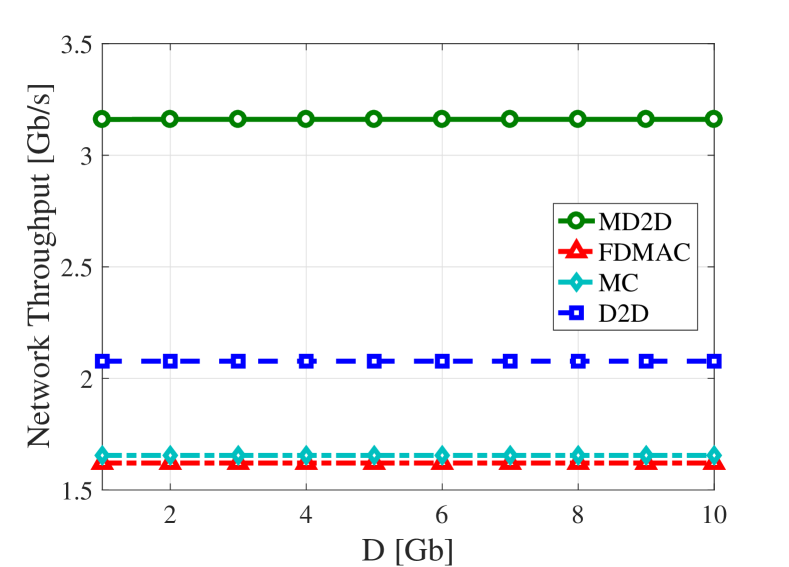
In Fig. 8, we plot the network throughput comparison with different multicast data sizes under NLOS transmission assumption. We can observe that our scheme achieves best, and still lower throughput is achieved due to higher propagation loss.
VI-C2 Energy Consumption
Fig. 9 compares the energy consumptions of the four schemes under different numbers of users. Clearly, the energy consumption increases linearly with the number of users. Observe from both Figs. 9 and 4 that our MD2D scheme consumes the lowest energy consumption and achieves the highest network throughput. This is because higher throughput means that the system can finish the task scheduling faster, which causes that the system consumes less energy. For example, when the number of users is , our MD2D consumes 1 J less energy, while increasing the network throughput by 1.6 Gb/s, compared with the second-best MC scheme. This clearly demonstrates the significant benefits of jointly exploiting multi-level code book and D2D communications.
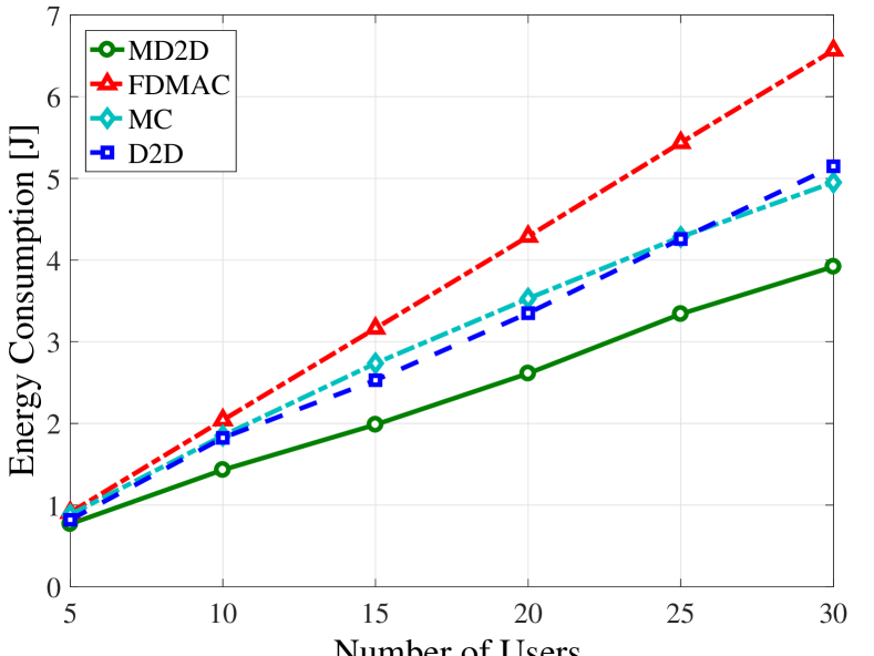
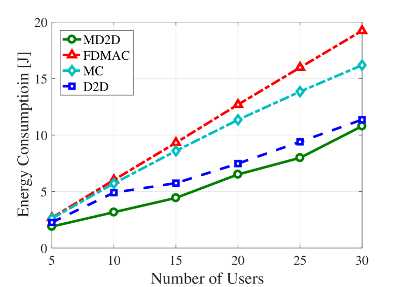
Fig. 10 plots the energy consumption comparison with different number of users under NLOS transmission assumption. From the results, we can observe that our scheme achieves lower energy consumption compared with other schemes. Compared with the LOS case, the energy consumption is much higher for all schemes since worse channel conditions under NLOS transmission assumption to complete the same multicast task.
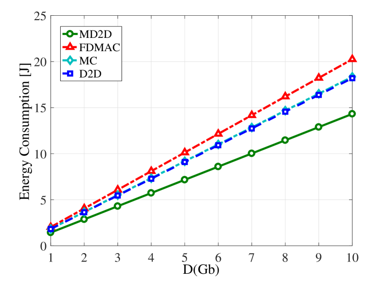
Fig. 11 plots the energy consumptions of the four schemes given different multicast data sizes. The energy consumption increases with since the system needs more time to transmit data. Not surprisingly, our MD2D scheme consumes the least energy, while attaining the highest network throughput. Also observe that the gaps of energy consumption between our MD2D and other schemes increase with the multicast data size. In particular, given the multicast data size Gb, our MD2D consumes 22% less energy than the second-best D2D scheme.
VI-C3 Energy Efficiency
The EE metric combines both the network throughput and energy consumption performance. In Fig. 12, we plot the EE metrics achieved by the four schemes given different numbers of users. With the increase of users, the traffic load of the network increases and the energy efficiency generally decreases, as can be seen from Fig. 12. Since network throughput affects energy consumption, and network throughput and energy consumption affect energy efficiency, as expected, MD2D achieves the highest energy efficiency performance because MD2D achieves the best NT performance and consumes the least energy among the four multicast schemes. In particular, given the number of users , our MD2D improves the energy efficiency by about 72% compared with the second-best MC scheme.
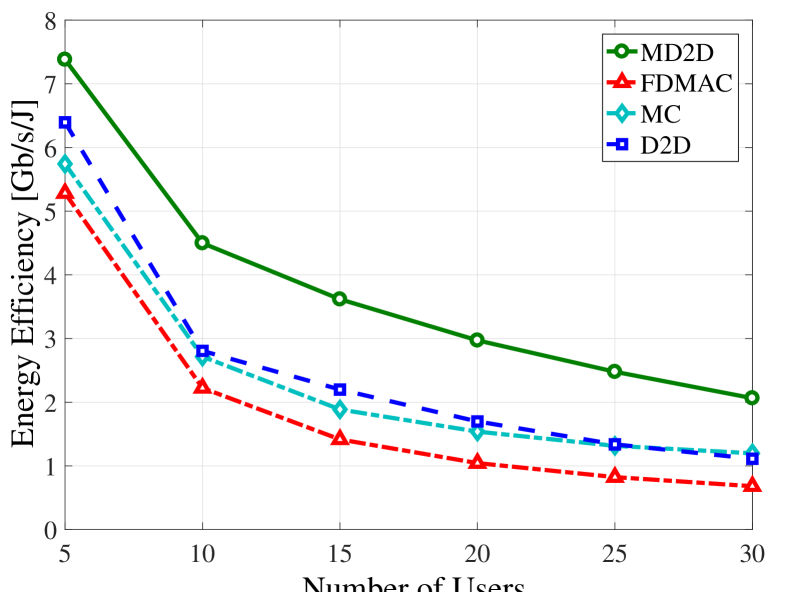
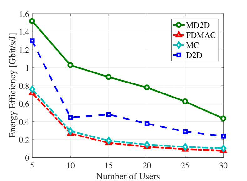
Fig. 13 plots the energy efficiency comparison with different number of users under NLOS transmission assumption. We can observe that our scheme has the highest energy efficiency among all the schemes. Compared with the results under the LOS assumption, the achieved energy efficiency is lower since lower throughput and higher energy consumption under NLOS transmissions.
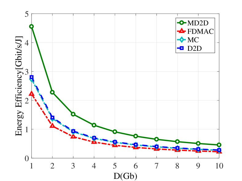
Fig. 14 compares the EE metrics of the four schemes under different multicast data sizes. Since higher energy consumption is necessary for larger multicast data size, the energy efficiency generally decreases with the multicast data size. Not surprisingly, our MD2D achieves the highest energy efficiency among the four schemes. Compared to the second-best D2D scheme, our MD2D improves the energy efficiency by about 64% and 66%, respectively, given the multicast data sizes Gb and Gb.
VII Conclusions
We have developed an efficient multicast scheduling scheme for mmWave small cells, which jointly exploits both D2D transmissions and multi-level antenna codebook to improve multicast efficiency. Our novel contribution has been twofold. Firstly, we have shown that the optimal multicast scheduling problem by jointly optimizing the utilizations of D2D transmissions and multi-level antenna codebook is NP-hard. Secondly, in order to obtain practical and efficient solution, we have developed a novel multicast scheduling scheme, called MD2D. More specifically, in our MD2D solution, an efficient user-partition and multicast-path-planning algorithm partitions users in the multicast group into subsets and selects the transmit node for each subset. Then an effective multicast scheduling algorithm schedules the transmission for each subset into each transmission phase. Performance evaluation has verified that our MD2D multicast scheduling scheme significantly outperforms the other two multicast scheduling schemes relying on D2D communications and multi-level antenna codebook alone, respectively, in terms of network throughput and energy efficiency. In the future work, we will analyze the relationship between the objective function and the parameters such as angle and radius thresholds in a theoretically way.
References
- [1] J. G. Andrews, “Can cellular networks handle 1000x the data?” Seminar given at University of Texas at Austin, Oct. 14, 2011.
- [2] Y. Zhu, Z. Zhang, Z. Marzi, C. Nelson, U. Madhow, B. Y. Zhao, and H. Zheng, “Demystifying 60GHz outdoor picocells,” in Proc. MobiCom 2014 (Maui, Hawaii), Sep. 7-11, 2014, pp. 5–16.
- [3] V. Chandrasekhar, J. G. Andrews, and A. Gatherer, “Femtocell networks: a survey,” IEEE Commun. Mag., vol. 46, no. 9, pp. 59–67, Sep. 2008.
- [4] M. Elkashlan, T. Q. Duong, and H.-H. Chen, “Millimeter-wave communications for 5G – part 2: applications [guest editorial],” IEEE Commun. Mag., vol. 53, no. 1, pp. 166–167, Jan. 2015.
- [5] T. S. Rappaport, J. N. Murdock, and F. Gutierrez, “State of the art in 60-GHz integrated circuits and systems for wireless communications,” Proc. IEEE, vol. 99, no. 8, pp. 1390–1436, Aug. 2011.
- [6] IEEE 802.15.3c Standard, Wireless Medium Access Control (MAC) and Physical Layer (PHY) Specifications for High Rate Wireless Personal Area Networks (WPANs) – Amendment 2: Millimeter-wave Based Alternative Physical Layer, 2009.
- [7] IEEE 802.11ad Standard, Wireless LAN Medium Access Control (MAC) and Physical Layer (PHY) Specifications – Amendment 3: Enhancements for Very High Throughput in the 60 GHz Band, 2012.
- [8] IEEE P802.11-Task Group ay, http://www.ieee802.org/11/Reports/tgay_update.htm.
- [9] J. Wang, Z. Lan, C.-W. Pyo, T. Baykas, C.-S. Sum, M. A. Rahman, J. Gao, R. Funada, F. Kojima, H. Harada, and S. Kato, “Beam codebook based beamforming protocol for multi-Gbps millimeter-wave WPAN systems,” IEEE J. Sel. Areas Commun., vol. 27, no. 8, pp. 1390–1399, Oct. 2009.
- [10] Z. Xiao, T. He, P. Xia, and X.-G. Xia, “Hierarchical codebook design for beamforming training in millimeter-wave communication,” IEEE Trans. Wireless Commun., vol. 15, no. 5, pp. 3380–3392, May 2016.
- [11] Z. Xiao, L. Zhu, J. Choi, X. Chao, and X. Xia, “Joint power allocation and beamforming for non-orthogonal multiple access (NOMA) in 5G millimeter-wave communications,” IEEE Transactions on Wireless Communications, vol. 17, no. 5, pp. 2961-2974, May 2018.
- [12] Z. Xiao, P. Xia, X. Xia, “Enabling UAV cellular with millimeter-wave communication: potentials and approaches,” IEEE Communications Magazine, vol. 54, no. 5, pp. 66-73, May 2016.
- [13] A. Finamore, M. Mellia, Z. Gilani, K. Papagiannaki, V. Erramilli, and Y. Grunenberger, “Is there a case for mobile phone content pre-staging?” in Proc. CoNEXT 2013 (Santa Barbara, CA), Dec. 9-12, 2013, pp. 321–326.
- [14] Y. Niu, L. Su, C. Gao, Y. Li, D. Jin, and Z. Han, “Exploiting device-to-device communications to enhance spatial reuse for popular content downloading in directional mmwave small cells,” IEEE Trans. Vehicular Technology, vol. 65, no. 7, pp. 5538–5550, Jul. 2016.
- [15] S. Naribole and E. Knightly, “Scalable multicast in highly-directional 60 GHz WLANs,” in Proc. SECON 2016 (London, UK), Jun. 27-30, 2016, pp. 1–9.
- [16] Y. Li, Z. Wang, D. Jin, and S. Chen, “Optimal mobile content downloading in device-to-device communication underlaying cellular networks,” IEEE Trans. Wireless Commun., vol. 13, no. 7, pp. 3596–3608, Jul. 2014.
- [17] J. Qiao, L. X. Cai, X. Shen, and J. W. Mark, “STDMA-based scheduling algorithm for concurrent transmissions in directional millimeter wave networks,” in Proc. ICC 2012 (Ottawa, Canada), Jun. 10-15, 2012, pp. 5221–5225.
- [18] L. X. Cai, L. Cai, X. Shen, and J. W. Mark, “Rex: a randomized exclusive region based scheduling scheme for mmWave WPANs with directional antenna,” IEEE Trans. Wireless Commun., vol. 9, no. 1, pp. 113–121, Jan. 2010.
- [19] C.-S. Sum, Z. Lan, R. Funada, J. Wang, T. Baykas, M. Rahman, and H. Harada, “Virtual time-slot allocation scheme for throughput enhancement in a millimeter-wave multi-Gbps WPAN system,” IEEE J. Sel. Areas Commun., vol. 27, no. 8, pp. 1379–1389, Oct. 2009.
- [20] C.-S. Sum, Z. Lan, M. A. Rahman, J. Wang, T. Baykas, R. Funada, H. Harada, and S. Kato, “A multi-Gbps millimeter-wave WPAN system based on STDMA with heuristic scheduling,” in Proc. GLOBECOM 2009 (Honolulu, Hawaii), Nov. 30-Dec. 4, 2009, pp. 1–6.
- [21] J. Qiao, L. X. Cai, X. S. Shen, and J. W. Mark, “Enabling multi-hop concurrent transmissions in 60 GHz wireless personal area networks,” IEEE Trans. Wireless Commun., vol. 10, no. 11, pp. 3824–3833, Nov. 2011.
- [22] Standard ECMA-387, High Rate 60 GHz PHY, MAC and HDMIPAL, 2010.
- [23] I. K. Son, S. Mao, M. X. Gong, and Y. Li, “On frame-based scheduling for directional mmWave WPANs,” in Proc. INFOCOM, 2012 (Orlando, FL), Mar. 25-30, 2012, pp. 2149–2157.
- [24] M. X. Gong, R. Stacey, D. Akhmetov, and S. Mao, “A directional CSMA/CA protocol for mmWave wireless PANs,” in Proc. WCNC 2010 (Sydney Australia), Apr. 18-21, 2010, pp. 1–6.
- [25] S. Singh, F. Ziliotto, U. Madhow, E. M. Belding, and M. Rodwell, “Blockage and directivity in 60 GHz wireless personal area networks: from cross-layer model to multihop MAC design,” IEEE J. Sel. Areas Commun., vol. 27, no. 8, pp. 1400–1413, Oct. 2009.
- [26] Q. Chen, J. Tang, D. T. C. Wong, X. Peng, and Y. Zhang, “Directional cooperative MAC protocol design and performance analysis for IEEE 802.11 ad WLANs,” IEEE Trans. Vehicular Technology, vol. 62, no. 6, pp. 2667–2677, Jul. 2013.
- [27] Y. Niu, Y. Li, D. Jin, L. Su, and D. Wu, “Blockage robust and efficient scheduling for directional mmWave WPANs,” IEEE Trans. Vehicular Technology, vol. 64, no. 2, pp. 728–742, Feb. 2015.
- [28] Y. Niu, C. Gao, Y. Li, L. Su, D. Jin, and A. V. Vasilakos, “Exploiting device-to-device communications in joint scheduling of access and backhaul for mmWave small cells,” IEEE J. Sel. Areas Commun., vol. 33, no. 10, pp. 2052–2069, Oct 2015.
- [29] H. Zhang, S. Huang, C. Jiang, K. Long, V. C. M. Leung, and H. V. Poor, “Energy efficient user association and power allocation in millimeter wave based ultra dense networks with energy harvesting base stations,” IEEE Journal on Selected Areas in Communications, vol. 35, no. 9, pp. 1936-1947, June 2017
- [30] H. Park, S. Park, T. Song, and S. Pack, “An incremental multicast grouping scheme for mmWave networks with directional antennas,” IEEE Commun. Let., vol. 17, no. 3, pp. 616–619, Mar. 2013.
- [31] J. Ning, T.-S. Kim, S. V. Krishnamurthy, and C. Cordeiro, “Directional neighbor discovery in 60 GHz indoor wireless networks,” Performance Evaluation, vol. 68, no. 9, pp. 897–915, Sep. 2011.
- [32] H. Deng and A. Sayeed, “Mm-Wave MIMO channel modeling and user localization using sparse beamspace signatures,” in Proc. SPAWC 2014 (Toronto, Canada), Jun. 22-25, 2014, pp. 130–134.
- [33] J. Choi, V. Va, N. Gonzalez-Prelcic, R. Daniels, C. R. Bhat, and R. W. Heath, “Millimeter-wave vehicular communication to support massive automotive sensing,” IEEE Communications Magazine, vol. 54, no. 12, pp. 160–167, Dec. 2016.
- [34] S. Geng, J. Kivinen, X. Zhao, and P. Vainikainen, “Millimeter-wave propagation channel characterization for short-range wireless communications,” IEEE Trans. Vehicular Technology, vol. 58, no. 1, pp. 3–13, Jan. 2009.
- [35] D. Pisinger, “Where are the hard knapsack problems?” Computers & Operations Research, vol. 32, no. 9, pp. 2271–2284, Sep. 2005.
- [36] Q. Chen, X. Peng, J. Yang, and F. Chin, “Spatial reuse strategy in mmWave WPANs with directional antennas,” in Proc. GLOBECOM 2012 (Anaheim, CA), Dec. 3-7, 2012, pp. 5392–5397.