Controllable coupled-resonator-induced transparency in a dual-recycled Michelson interferometer
Abstract
We theoretically and experimentally study the effect of the coupled-resonator-induced transparency in the Michelson interferometer with the dual-recycled configuration, which is equivalent to the adjustable coupled resonator. The coupling strength, corresponding to the splitting of the reflection spectrum and associated with the width of the coupled-resonator-induced transparent window, can be controlled by adjusting the arm lengths, i.e., the relative phase of the interference arms on the 50/50 beam splitter. Thus, this tunability of the coupling strength can be very fast, and the absorptive and dispersive properties can be effectively controlled. This work provides a new system to coherently control and storage optical field.
The destructive interference between the excitation pathways in the three level atomic system, which is well known as the electromagnetically induced transparency (EIT) harris ; Marangos ; Fleischhauer , has been widely studied and has attracted many attentions in the past twenty years since the first experiment was reported Boller . The steep dispersion and the low absorption at the EIT window make it become the primary choice for coherent optical information storage and freeze the light hau ; Kash ; Budker ; Liu1 ; philips , even storing quantum state in quantum information process Honda ; Appel ; Yan ; xu .
The similar coherence and interference phenomenon, named as EIT-like effect, has been demonstrated in the classical systems such as plasma harris2 ; Litvak ; Shvets , mechanical or electric oscillators Hemmer ; Garrido , coupled optical resonators Opatrny-2001 ; Smith-2004 ; Smith-2004-1 ; Maleki-2004 ; Yanik-2004 ; Di , optical parametric oscillators ma ; ye1 ; ye2 , optomechanical systems Weis ; Safavi ; marquardt and even some metamaterial configurations fan ; jenkins ; zhu . Especially, the analog of EIT in coupled optical resonators, also called coupled-resonator-induced transparency, has made great progress in experiment, which has been reported in the different optical systems, such as compound glass waveguide platform using relatively large resonators Chu , fiber ring resonators Dumeige , coupled fused-silica microspheres Naweed-2005 ; Totsuka , integrated micron-size silicon optical resonator systems Xu-2006 ; Li ; lanyang ; lipson , photonic crystal cavities Yang and graphene-ring resonators shubin . Two dynamically tuned resonators for stopping light have been proposed theoretically Maleki-2004 ; Yanik-2004 ; Otey and demonstrated experimentally Xu-2007 . These works provide the new ways of utilizing coupled optical resonators for the optical communication and the simulation of coherent effect in quantum optics. In this paper, we present a new optical system to realize coupled-resonator-induced transparency, in which the Michelson interferometer with the dual-recycled configuration is employed. This system is equivalent to the coupled resonators with tunable coupling strength. The absorptive and dispersive properties can be effectively controlled by adjusting the arm lengths, i.e., the relative phase of the interference arms on the 50/50 beam splitter. This method can realize the very fast tuning of the coupling strength in the coupled-resonator-induced transparency. It would be useful for the capture, storage, and release of the light, even quantum field.
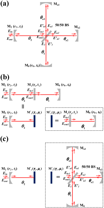
The schematic diagram is shown in Fig. 1(a). A continuous wave laser feeds a dual-recycled Michelson interferometer, which is separated by a 50/50 beam splitter (BS) into two orthogonal directions and reflected back by two mirrors ( and ). Another two mirrors are placed on the input path () and output path () of the Michelson interferometer, respectively. This configuration is so called dual recycling, i.e., the power (input path) recycling and the signal (output path) recycling, which was introduced by Meers into the Michelson interferometer for reflecting the sideband back to the interferometer meers . Thus the signal can be enhanced in the gravitational wave detection. The experimental demonstration was accomplished by Strain strain in 1991. This configuration has been applied to the Advanced LIGO, which can significantly extend the detection range, improve the sensitivity and induce the first detection of detection of gravitational waves emitted from the merger of two black holes GW1 ; GW2 ; GW3 .
In this paper, it is employed to study the coupled-resonator induced transparency. For simplicity, the length from the 50/50 BS to the four end reflective mirrors have the same optical length in our scheme. And the fine adjustment of the optical lengths or the relative phases can be implemented by changing the voltage of the piezoelectric transducers (PZT) mounted on the mirrors. Consequently controlling the four mirrors can make the laser resonant in the interferometer. At the same time, the relative phases of two interferometer arms at the 50/50 BS can be controlled. So the reflectivity (or transmissivity) at the 50/50 BS can be adjusted. Thus the system can be regarded as two coupled resonators whose coupling strength is controllable, as shown in Fig. 1(b). For an usual configuration of two coupled resonators, a mirror with adjustable transmissivity (or reflectivity) is placed in the middle of the standing wave cavity. The coupling strength of the coupled cavity mainly relies on the transmissivity of the middle mirror, usually which is difficult to be controlled or can not be changed. However, the transmissivity (or the reflectivity) of the middle mirror can be changed easily in our scheme because of the controllability of the interference of two interferometer arms at the 50/50 BS. Therefore the transparent window, the absorptive and the dispersive properties of the EIT-like effect can be manipulated. Moreover, in principle it suits any laser frequency in the coating band width of the mirrors. EIT effect is the Fano interference among the different transition pathways, which can be realized in quantum systems (such as in atom) or classic systems (such as coupled resonators). However, optical cavity, which is linear optical system, can be used as classic or quantum devices. EIT in the atomic system can be used to store the classical optical pulse or quantum field (such as squeezed light Honda ; Appel ). Similarly, coupled-resonator-induced transparency can also be used to store the classical optical pulse or quantum field (such as squeezed light). These characteristics make this system easily meet the requirements of the quantum storage in the quantum information, such as for squeezed light Di .
First, a single cavity is considered (for example, inside dash line box of Fig. 1(b)), whose reflected coefficient is written as
| (1) |
according to the input and output relationship. Here, and are input and reflected optical field. and are the reflectivity of the input mirror and the other mirror respectively, where and . is the single-pass phase shift of the intracavity field. Here and are the resonant frequency and the frequency detuning of the laser field respectively, is the single-pass time (the four arms have the same optical length, so we set ). Therefore a single cavity can be regarded as a mirror (as shown inside dash line box of Fig. 1(b)) with and . Then the reflected coefficient of two coupled resonators can be obtained by taking an iterative approach as shown in Fig. 1(b)
| (2) |
Now we can use the similar method to calculate the reflected coefficient of the dual-recycled Michelson interferometer. First, we consider a single cavity consists of the 50/50 BS with two interferometer arms and the signal recycling mirror as shown inside dash line box of Fig. 1(c). The two mirrors and of interferometer arms are high reflective. According to the input and output relationship
| (3) |
| (4) |
and
| (5) |
we can obtain the reflected coefficient of the equivalent single cavity
| (6) |
where, . Thus, the 50/50 BS with two interferometer arms can be regarded as the middle mirror of two coupled resonators with the reflectivity of , which can be controlled easily by the relative phase between two interferometer arms. This relative phase can be manipulated very fast, for example through electro-optic modulator (EOM). Note that the extra phase is introduced in this configuration. Thus the free spectrum range of the equivalent single cavity is for the equivalent cavity 1 and for cavity 2. At last, the reflected coefficient of the dual-recycled Michelson interferometer is obtained by the iterative approach as shown in Fig. 1(c), which is the same as Eq. 2.
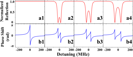
EIT and Autler-Townes splitting have a similar transparency window in the absorption or transmission spectrum, despite the differences in their underlying physics. While the transparency window in EIT results from Fano interference among different transition pathways, in Autler-Townes splitting it is the result of strong field-driven interactions leading to the splitting of energy levels. All-optical analogues of EIT and Autler-Townes splitting in coupled whispering-gallery-mode resonators lanyang were studied by choosing the cavity parameters. Here, we don’t focus on discrimination of two phenomena. EIT and Autler-Townes splitting can also be realized in the dual-recycled Michelson interferometer by choosing the suitable cavity parameters. The theoretical calculation results of the EIT-like effect in the dual-recycled Michelson interferometer are presented in Fig. 2. The coupling strength of the middle mirror can be expressed as ma
| (7) |
The splitting of the spectra that depend on the coupling strength of the coupled cavity can be adjusted by controlling the interference of the optical field on the 50/50 BS, which are well explained above the theoretical analysis. Here, the reflective spectrum and the corresponding phase shift at are obtained from the magnitude and phase of the reflected coefficient by tuning the frequency of injection laser with the wavelength nm. The optical lengths are mm and the reflectivity of the four end mirrors are and . The phase difference and of two arms in Fig. 2 are 0, , and , corresponding to the reflectivity of the middle mirror , , , , respectively (the coupling strength of the middle mirror , MHz, MHz, MHz according to Eq. 7). When we start to set two cavities to be resonant simultaneously (that is increased coupling strength), the single resonance split into two resonances whose spectral distance (that is mode splitting) is increased (from the left to the left curve) with increasing coupling strength.
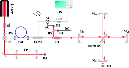
The experimental setup is shown in Fig. 3. A diode-pumped continuous-wave ring single-frequency laser provides the infrared light of 260 mW at 1064 nm. The laser is divided into two parts after an optical isolator. One part is injected into a confocal Fabry-Perot (F-P) cavity (the free spectrum range and the linewidth are 1.5 GHz and 10 MHz respectively, the finesse is 150) to monitor the laser frequency. The other is coupled into a single-mode polarization-maintaining fiber to clean the spatial modes of the laser. The output of the fiber passes through the electro-optic modulation with modulation frequency of 114.5 MHz and another optical isolator, then is injected into the dual-recycled Michelson interferometer. A 50/50 BS is oriented at 45 degrees to the laser beam. The power recycling mirror and the signal recycling mirror have the reflectivity of 93 at 1064 nm, while and are the highly reflective mirrors for 1064 nm. All the four mirrors have radius of curvature of 30 mm and are all mounted on PZT to tune the length of cavity subtly. The optical lengthes from the 50/50 BS to the four end reflective mirrors are about mm. In fact, it is difficult to make the four arms completely same. But the optical length difference is very small and it does not influence on the reflective spectra for several spectrum range. The free spectrum range of the single cavity is 2.66 GHz. The reflected field from the mirror of the dual-recycled Michelson interferometer is detected at the reflective window of the optical isolator 2. The reflected field from the optical isolator 2 is divided into two parts. One part is measured by detector 1 and its signal as the reflection spectrum is directly shown on the oscilloscope (OS). And the other part is detected by detector 2 with a broad detection bandwidth, and the output signal is combined with the local signal at a mixer and the low-frequency mixed signal as the phase shift of the EIT-like effect is collected by OS. This method corresponds to the Pound-Drever-Hall technique to obtain the error signal.
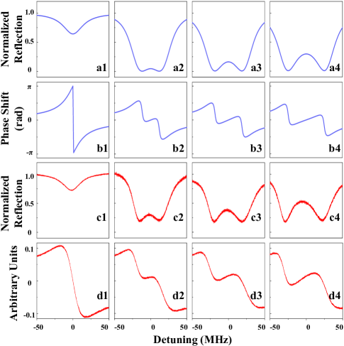
The measurement results are plotted in Fig. 4 (c1)-(c4) and (d1)-(d4) when the laser frequency is scanned. The voltages on the PZT’s are controlled by four high voltage amplifier to make the laser resonant with the system and to control two arms interference phases of the intracavity fields. In Fig. 4(c1), a dip appears in the reflective spectrum, which corresponds to the absorption profile of the equivalent single cavity since the two interferometer arms generate the constructive interference for the input mirror side at the 50/50 BS. A transparent window appears in the middle of the absorption profile as shown in Fig. 4(c2) when adding the coupling with the second cavity by controlling the relative phase of the two interferometer arms. And this transparent window becomes broader as shown in Fig. 4(c3) and (c4) when the coupling strength is increased further. Fig. 4(d1)-(d4) are the corresponding phase shift. The experimental results clearly display the coupled-resonator-induced transparent phenomena in the dual-recycled Michelson interferometer. Fig. 4(a1)-(a4) and (b1)-(b4) show the theoretical plots according to the experimental parameters, which are good agreement with the experimental results. Here, the intracavity loss is considered with in the theoretical calculation.
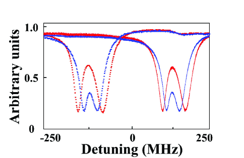
Furthermore, this system also displays more degrees of flexibility. The center frequency of the transparent window can be manipulated by the length from the 50/50 BS to the four end reflective mirrors. The center frequency of the transparent window is shifted MHz for the solid line and MHz for the dotted line, as shown in Fig. 5.
In conclusion, we study the coupled-resonator-induced transparency in the Michelson interferometer with dual-recycled configuration. This system is equivalent to the adjustable coupled resonator. The absorption and dispersion properties can be controlled by manipulating two interferometer arms. This work takes the first step of manipulating optical field using the dual-recycled Michelson interferometer and provides a scheme for the future studies on slow light, storage and retrieval. The basic requirements of a light-stopping process (capture, storage, and release of the light pulse) are that the coupled resonator system supports a large-bandwidth state to accommodate the input pulse bandwidth, which is then dynamically tuned to an narrow-bandwidth state to stop the pulse and done reversibly after some storage time to release light pulse. The current structure of dual-recycled Michelson interferometer in our experiment can satisfy this requirement completely to tune the cavity bandwidth dynamically. We also hope that this work will stimulate the research of manipulating the quantum optical fields, such as squeezed light Di , which is similar to store the squeezed light in atomic vapor Honda ; Appel .
† Corresponding author email: jzhang74@sxu.edu.cn, jzhang74@yahoo.com
Acknowledgements.
This research was supported in part by the MOST (Grant No. 2016YFA0301602), National Natural Science Foundation of China (NSFC) (Grant No. 11234008, 11361161002, 615712768, 11654002, 11804206), Natural Science Foundation of Shanxi Province (Grant No. 2015011007), Research Project Supported by Shanxi Scholarship Council of China (Grant No. 2015-002).References
- (1) S. E. Harris, “Electromagnetically Induced Transparency”, Phys. Today 50, 36 (1997).
- (2) J. P. Marangos, Electromagnetically Induced Transparency, J. Mod. Opt. 45, 471 (1998).
- (3) M. Fleischhauer, A. Imamoglu, and J. Marangos, Electromagnetically Induced Transparency: Optics in Coherent Media, Rev. Mod. Phys. 77, 633 (2005).
- (4) K. J. Boller, A. Imamoglu, and S. E. Harris, Observation of Electromagnetically Induced Transparency, Phys. Rev. Lett. 66, 2593 (1991).
- (5) L. V. Hau, S. E. Harris, Z. Dutton, and C. H. Behroozi, “Light Speed Reduction to 17 Metres per Second in an Ultra-Cold Atomic Gas”, Nature 397, 594 (1999).
- (6) M. M. Kash, V. A. Sautenkov, A. S. Zibrov, L. Hollberg, G. R. Welch, M. D. Lukin, Y. Rostovtsev, E. S. Fry, and M. O. Scully, ”Ultraslow Group Velocity and Enhanced Nonlinear Optical Effects in a Coherently Driven Hot Atomic Gas”, Phys. Rev. Lett. 82, 5229 (1999).
- (7) D. Budker, D. F. Kimball, S. M. Rochester, and V. V. Yashchuk, ”Nonlinear Magneto-Optics and Reduced Group Velocity of Light in Atomic Vapor with Slow Ground State Relaxation”, Phys. Rev. Lett. 83, 1767 (1999).
- (8) C. Liu, Z. Dutton, C. H. Behroozi, and L. V. Hau, “Observation of Coherent Optical Information Storage in an Atomic Medium Using Halted Light Pulses”, Nature 409, 490 (2001).
- (9) D. F. Phillips, A. Fleischhauer, A. Mair, R. L. Walsworth, and M. D. Lukin, “Storage of Light in Atomic Vapor”, Phys. Rev. Lett. 86, 783 (2001).
- (10) K. Honda, D. Akamatsu, M. Arikawa, Y. Yokoi, K. Akiba, S. Nagatsuka, T. Tanimura, A. Furusawa, and M. Kozuma, ”Storage and Retrieval of a Squeezed Vacuum”, Phys. Rev. Lett. 100, 093601 (2008).
- (11) J. Appel, E. Figueroa, D. Korystov, M. Lobino, and A. I. Lvovsky et al., ”Quantum Memory for Squeezed Light”, Phys. Rev. Lett. 100, 093602 (2008).
- (12) Z. Yan, L. Wu, X. Jia, Y. Liu, R. Deng, S. Li, H. Wang, C. Xie, K. Peng, ”Establishing and Storing of Deterministic Quantum Entanglement among Three Distant Atomic Ensembles”, Nat. Commun. 8, 718 (2017)
- (13) Z. Xu, Y. Wu, L. Tian, L. Chen, Z. Zhang, Z. Yan, S. Li, H. Wang, C. Xie, and K. Peng, “Long Lifetime and High-Fidelity Quantum Memory of Photonic Polarization Qubit by Lifting Zeeman Degeneracy”, Phys. Rev. Lett. 111, 240503 (2013).
- (14) S. E. Harris, “Electromagnetically Induced Transparency in an Ideal Plasma”, Phys. Rev. Lett. 77(27), 5357 (1996).
- (15) A. G. Litvak and M. D. Tokman, ”Electromagnetically Induced Transparency in Ensembles of Classical Oscillators”, Phys. Rev. Lett. 88, 095003 (2002).
- (16) G. Shvets and J. S. Wurtele, ”Transparency of Magnetized Plasma at the Cyclotron Frequency”, Phys. Rev. Lett. 89, 115003 (2002).
- (17) P. R. Hemmer and M. G. Prentiss, ”Coupled-Pendulum Model of the Stimulated Resonance Raman Effect”, J. Opt. Soc. Am. B 5, 1613 (1988).
- (18) C. L. Garrido Alzar, M. A. G. Martinez, and P. Nussenzveig, ”Classical Analog of Electromagnetically Induced Transparency”, Am. J. Phys. 70, 37 (2002).
- (19) T. Opatrny and D. G. Welsch, ”Coupled Cavities for Enhancing the Cross-Phase-Modulation in Electromagnetically Induced Transparency”, Phys. Rev. A 64, 023805 (2001).
- (20) D. D. Smith, H. Chang, K. A. Fuller, A. T. Rosenberger, and R. W. Boyd, ”Coupled-Resonator-Induced Transparency”, Phys. Rev. A 69, 063804 (2004).
- (21) D. D. Smith and H. Chang, ”Coherence Phenomena in Coupled Optical Resonators”, J. Mod. Opt. 51, 2503 (2004).
- (22) L. Maleki, A. B. Matsko, A. A. Savchenkov, and V. S. Ilchenko, ”Tunable Delay Line with Interacting Whispering-Gallery-Mode Resonators”, Opt. Lett. 29, 626 (2004).
- (23) M. F. Yanik, W. Suh, Z. Wang, and S. Fan, ”Stopping Light in a Waveguide with an All-Optical Analog of Electromagnetically Induced Transparency”, Phys. Rev. Lett. 93, 233903 (2004).
- (24) K. Di, C. D. Xie, and J. Zhang, “Coupled-Resonator-Induced Transparency with a Squeezed Vacuum”, Phys. Rev. Lett. 106, 153602 (2011).
- (25) H. Ma, C. Ye, D. Wei, and J. Zhang, “Coherence Phenomena in the Phase-Sensitive Optical Parametric Amplification inside a Cavity”, Phys. Rev. Lett. 95, 233601 (2005).
- (26) C. Ye, and J. Zhang, “Absorptive and Dispersive Properties in the Phase-Sensitive Optical Parametric Amplification inside a Cavity”, Phys. Rev. A, 73(2), 023818 (2006).
- (27) C. Ye, and J. Zhang, “Electromagnetically Induced Transparency-Like Effect in the Degenerate Triple-Resonant Optical Parametric Amplifier”, Opt. Lett. 33(6), 1911-1913 (2008).
- (28) S. Weis, et al. ”Optomechanically Induced Transparency”. Science 330, 1520 (2010).
- (29) A. H. Safavi-Naeini, et al. ”Electromagnetically Induced Transparency and Slow Light with Optomechanics”, Nature 472, 69 (2011).
- (30) A. Kronwald, and F. Marquardt, ”Optomechanically Induced Transparency in the Nonlinear Quantum Regime”, Phys. Rev. Lett. 111, 133601 (2013).
- (31) Y. Fan, T. Qiao, F. Zhang, Q. Fu, J. Dong, B. Kong, and H. Li, ”An Electromagnetic Modulator Based on Electrically Controllable Metamaterial Analogue to Electromagnetically Induced Transparency”, Sci. Rep. 7, 40441 (2017).
- (32) S. D. Jenkins, and J. Ruostekoski, ”Metamaterial Transparency Induced by Cooperative Electromagnetic Interactions”, Phys. Rev. Lett. 111, 147401 (2013).
- (33) L. Zhu, F. Meng, L. Dong, Q. Wu, B. Che, J. Gao, J. Fu, K. Zhang, and G. Yang, ”Magnetic Metamaterial Analog of Electromagnetically Induced Transparency and Absorption”, J. Appl. Phys. 117 17D146 (2015).
- (34) S. T. Chu, W. Pan, S. Suzuki, B. E. Little, S. Sato, and Y. Kokubun, “Temperature Insensitive Vertically Coupled Microring Resonator Add/Drop Filters by Means of a Polymer Overlay”, IEEE Photonics Technol. Lett. 11, 1426 (1999).
- (35) Y. Dumeige, T. K. N. Nguyên, L. Ghişa, S. Trebaol, and P. Féron, “Measurement of the Dispersion Induced by a Slow-Light System Based on Coupled Active-Resonator-Induced Transparency”, Phys. Rev. A 78, 013818 (2008).
- (36) A. Naweed, G. Farca, S. I. Shopova, and A. T. Rosenberger, ”Induced Transparency and Absorption in Coupled Whispering-Gallery Microresonators”, Phys. Rev. A 71, 043804 (2005).
- (37) K. Totsuka, N. Kobayashi, and M. Tomita, “Slow Light in Coupled-Resonator-Induced Transparency”, Phys. Rev. Lett. 98, 213904 (2007).
- (38) Q. Xu, S. Sandhu, M. L. Povinelli, J. Shakya, S. Fan, and M. Lipson, ”Experimental Realization of an On-Chip All-Optical Analogue to Electromagnetically Induced Transparency”, Phys. Rev. Lett. 96, 123901 (2006).
- (39) B. Li, Y. Xiao, C. Zou, X. Jiang, Y. Liu, F. Sun, Y. Li, and Q. Gong, “Experimental Controlling of Fano Resonance in Indirectly Coupled Whispering-Gallery Microresonators”, Appl. Phys. Lett. 100, 021108 (2012).
- (40) B. Peng, S. K. Özdemir, W. Chen, F. Nori, and L. Yang, ”What is and what is not electromagnetically induced transparency in whispering-gallery microcavities”, Nat. Commun. 5, 5082 (2014).
- (41) A. Dutt, S. Miller, K. Luke, J. Cardenas, A. L. Gaeta, P. Nussenzveig, and M. Lipson, “Tunable Squeezing Using Coupled Ring Resonators on a Silicon Nitride Chip”, Opt. Lett. 41, 223 (2016).
- (42) X. Yang, M. Yu, D. Kwong, and C. Wong, “All-Optical Analog to Electromagnetically Induced Transparency in Multiple Coupled Photonic Crystal Cavities”, Phys. Rev. Lett. 102, 173902 (2009).
- (43) Y. Wang, C. Xue, Z. Zhang, H. Zheng, W. Zhang, and S. Yan, “Tunable Optical Analog to Electromagnetically Induced Transparency in Graphene-Ring Resonators System”, Sci. Rep. 6, 38891 (2016).
- (44) C. R. Otey, M. L. Povinelli, and S. Fan, ”Capturing Light Pulses into a Pair of Coupled Photonic Crystal Cavities”, Appl. Phys. Lett. 94, 231109 (2009).
- (45) Q. Xu, P. Dong, and M. Lipson, ”Breaking the Delay-Bandwidth Limit in a Photonic Structure”, Nature Phys. 3, 406 (2007).
- (46) B. J. Meers, “Recycling in Laser-Interferometric Gravitational-Wave Detectors”, Phys. Rev. D, 38(8), 2317-2326 (1988).
- (47) K. A. Strain, and B. J. Meers, “Experimental Demonstration of Dual Recycling for Interferometric Gravitational-Wave Detectors”, Phys. Rev. Lett., 66(11), 1391-1394 (1991).
- (48) B. P. Abbott et al. (LIGO Scientific Collaboration and the Virgo Collaboration), ”Observation of Gravitational Waves from a Binary Black Hole Merger”, Phys. Rev. Lett. 116, 061102 (2016).
- (49) B. P. Abbott et al. (LIGO Scientific Collaboration and the Virgo Collaboration), ”GW150914: Implications for the Stochastic Gravitational-Wave Background from Binary Black Holes”, Phys. Rev. Lett. 116, 131102 (2016).
- (50) B. P. Abbott et al. (LIGO Scientific Collaboration and the Virgo Collaboration), ”GW150914: The Advanced LIGO Detectors in the Era of First Discoveries”, Phys. Rev. Lett. 116, 131103 (2016).