The ‘Recovered Space’ Advection Scheme for Lowest-Order Compatible Finite Element Methods
Abstract
We present a new compatible finite element advection scheme for the compressible Euler equations. Unlike the discretisations described in Cotter and Kuzmin (2016) and Shipton et al (2018), the discretisation uses the lowest-order family of compatible finite element spaces, but still retains second-order numerical accuracy. This scheme obtains this second-order accuracy by first ‘recovering’ the function in higher-order spaces, before using the discontinuous Galerkin advection schemes of Cotter and Kuzmin (2016). As well as describing the scheme, we also present its stability properties and a strategy for ensuring boundedness. We then demonstrate its properties through some numerical tests, before presenting its use within a model solving the compressible Euler equations.
Keywords: Advection scheme; Discontinuous Galerkin; Compatible finite element methods; Numerical weather prediction
1 Introduction
Over the past few decades, technological improvements in parallel computing
have driven increased performance of numerical models of weather and
climate systems, allowing them to be run at increasingly finer resolutions
and delivering significantly improved predictive capabilities.
However, the traditional latitude-longitude grids used in these models
are leading to the approach of a scalability bottleneck:
improvements in potential computational power no longer lead to
improved model performance, as the clustering of points around the poles
limits the rate of data communication (the so-called ‘pole problem’).
This has led to a search for alternative grids for these models.
However, latitude-longitude grids (coupled with Arakawa C-grid staggering)
provided many properties important for accurate representation of
atmospheric motion: avoiding spurious pressure modes, accurately
representing geostrophic balance and not supporting spurious gravity-inertia
or Rossby wave modes.
These properties are described in [1].
It is therefore desirable that any alternative grid should
maintain these properties.
Finite element methods have therefore been explored, as they offer
the opportunity to solve the equations of motion with arbitrary
mesh structures.
Extending previous work into the use of mixed finite element methods
for such geophysical fluid models, [2] proposed
mixed finite element methods with two crucial properties.
Firstly, that the finite element spaces used should be compatible
with one another, so that the discrete versions of the vector calculus
operators preserve the properties that
and that .
Secondly, the function spaces used for the velocity and pressure variables
should be chosen to fix the ratio of velocity to pressure degrees of freedom
per element to be 2:1.
This was shown in [2] to be a necessary condition for the
avoidance of spurious inertia-gravity and Rossby wave modes.
[2] also proposed two sets of finite element spaces
that would meet these criteria on quadrilateral and triangular elements.
[2] has been followed by a series of works into the use
of compatible finite element methods for use in numerical weather models,
for instance [3], [4], [5],
[6] and [7].
Most relevant to the work here are [8], which presented a full discretisation
of the Euler-Boussinesq equations in the context of compatible finite element methods;
and [9], which introduced a
embedded discontinuous Galerkin transport scheme.
The compatible finite element framework thus suggests using particular
compatible finite element spaces for the velocity and density .
For horizontal grids, the examples given in [2] are
with on quadrilateral elements,
and with on triangular elements.
Here is the space of -th degree Raviart-Thomas quadrilateral elements,
is the space of discontinuous -th order polynomial elements on quadrilaterals,
is the space of -th degree Brezzi-Douglas-Fortin-Marini triangular elements
and finally is the space of -th order polynomial elements on triangles.
Most of these elements appear in the Periodic Table of Finite Elements [10].
Another set of spaces to consider are those used in 2D vertical slices, which are relevant for test cases
used in developing the model.
These models are constructed as the tensor product of a 1D horizontal space with a
1D vertical space .
We will denote the space of -th degree continuous polynomial elements by ,
and that of -th degree discontinuous polynomials by .
In this case horizontal velocities lie in the space ,
vertical velocities are in , whilst the density is in
.
In order to mimic the Charney-Philips grid used in
finite difference models, the potential temperature
lies in the partially-continuous space,
,
i.e. temperature degrees of freedom (DOFs) are co-located with
those for vertical velocity, as in [6]
and [8].
The construction of tensor product finite element spaces is described by [11].
Throughout the rest of the paper we will consider the case that for quadrilateral elements in this vertical slice set-up, although the advection scheme can be applied more generally.
Advection schemes for the family of spaces have been presented in [9],
[8] and [7].
An advantage of the degree was that it is easy to
formulate for it advection schemes
with the property of
second-order numerical accuracy, i.e. that the error
associated with the discretisation of the advection
process is proportional to
, the grid size squared.
This is one of the crucial properties of discretisations for
numerical weather models
listed in [1].
However, in the families, coupling of the dynamics to the
sub-grid physical processes
(for example the effects of moisture or radiation)
may be more challenging than for case.
The effects of such physical processes are commonly expressed
as tendencies to the prognostic variables and typically
calculated pointwise at the degrees of freedom.
For the fields that are piecewise constant or linear,
the pointwise values can be interpreted as mean quantities
for that element and the tendencies can be formulated as such.
In the case on quadrilateral elements, the temperature and moisture fields
are piecewise quadratic functions in the vertical,
and the physical interpretation of the values at the degrees
of freedom becomes less clear.
It is therefore desirable to consider spaces using
advection schemes that have second-order numerical accuracy.
The main result of this paper is thus a presentation of such an
advection scheme for this set of spaces.
This scheme has been inspired by the results of
[12], which implies
that it is possible to reconstruct a discontinuous zeroth-order
field in a continuous first-order space, via
an averaging operation that has second-order numerical
accuracy.
After describing the scheme in Section 2, this paper
presents several of its properties in Section 3,
including a general argument of its stability and von Neumann
analysis of the scheme in three particular cases.
Section 4 presents the results of numerical
tests demonstrating the second-order numerical accuracy of the
scheme, the stability calculations of Section
3.2 and the use of a limiter within
the advection scheme.
Finally, the use of the advection scheme within a model
of the compressible Euler equations is presented in Section
5.
2 The ‘Recovered Space’ Scheme
The key idea upon which this scheme is based is the family of
recovered finite element methods introduced by
[12]. These methods combine features of
discontinuous Galerkin approaches with conforming finite element
methods. They are similar to other recovery methods, such as those in
[13, 14], in that they reconstruct
higher-order polynomials from lower order data in a patch of cells.
They differ in that they do not attempt to reproduce polynomials of a
certain degree exactly. Instead, they involve mapping discontinuous
finite element spaces to continuous ones, via recovery operators,
relying on analysis estimates of stability and accuracy.
The scheme that we will introduce involves the use of one
of these operators to recover a function in a
discontinuous first-order space
from one in a discontinuous zeroth-order space.
To do this, we first recover a first-order continuous function
from the zeroth-order discontinuous function using an averaging
operator described in [12] and
[15].
This operator finds the values for any degree of freedom
shared between elements in a continuous function space,
by averaging between the values of the surrounding degrees of
freedom from the discontinuous space.
Once this operator has been applied, existing transport schemes
can be used to perform the advection upon the recovered field.
This approach is compatible when the transport equation is in
‘advective’ form
| (2.1) |
or ‘conservative’ form
| (2.2) |
where is the quantity to be transported by velocity . However most of our analysis will focus on the application of this scheme to the ‘advective’ form of the equation, under which the mass over the whole domain will only be necessarily conserved when the flow is incompressible, .
2.1 The Scheme
First we will define a set of spaces that our functions will lie in.
Let be the lowest-order finite element space in which the
initial field lies, where is our spatial domain***This spatial domain can be arbitrary, but with geophysical applications in mind we anticipate the scheme being used upon rectangular or cuboid domains (with or without periodicity) or spherical shells.
However the recovery operator that we consider in Section 2.3 is intended for use in flat spaces or with only scalar fields in curved spaces and we do not yet consider the application to transport of vector fields in curved spaces.
Therefore in this work we will predominantly consider rectangular domains with a vertical coordinate, with rigid walls at the top and bottom edges..
is then the space of next degree, which will be fully discontinuous.
We also have that .
is the fully continuous space of
same degree as ,
whilst is a
broken (i.e. fully discontinuous) version of .
In many cases, and will coincide.
We now define a series of operators to map between these spaces.
Definition 1.
The recovery operator acts upon a function in the initial space to make a function in the continuous space of higher-degree, so that . The operator has second-order numerical accuracy.
Assumption 1.
The recovery operator has the property that for all , there is some such that .
Definition 2.
The injection operator identifies a function in , or as a member of . This must be numerically implemented, although it does nothing else mathematically.
Definition 3.
The projection operator , is defined to give , from , by finding the solution to
| (2.3) |
Definition 4.
The advection operator , represents the action of performing one time step of a stable discretisation of the advection equation (in either advective or conservative form) and has second-order numerical accuracy in space.
Definition 5.
The projection operator will have two forms. The first, , is defined to give from , by finding the solution to
| (2.4) |
where and .
The second form, , is
composed of two operations: , interpolation
into the broken space by pointwise evaluation at degrees of freedom, and , recovery
from the broken space to the original space, restoring continuity
via the reconstruction operator from [12].
can thus be written as .
In the case that is fully discontinuous, and will be identical operations. However for fully or partially continuous , prevents the formation of any new maxima and minima, whereas does not. We may thus use as the projection operator when trying to bound the transport, such as for a moisture species. Further discussion can be found in Section 2.4. The drawback is that whilst preserves the mass (setting gives ), does not necessarily do so.
Definition 6.
The ‘recovered space’ scheme then takes the function at the -th time step and returns the function at the -th time step by performing the following series of operations:
| (2.5) |
where could be either or .
An important property of this scheme is that in the absence of flow, the field being advected must remain unchanged. In this case will be the identity, and since , then . In practice, mass will be only be conserved up to the precision used by the numerical solver for .
2.2 Example Spaces
In this section we give an example set of spaces
on quadrilateral elements
that can be used for this scheme,
in the context of 2D vertical slice problems.
The variables that we will consider are the density , velocity and
potential temperature .
| Variable | ||||
|---|---|---|---|---|
![[Uncaptioned image]](/html/1811.06956/assets/DG0.png) |
![[Uncaptioned image]](/html/1811.06956/assets/DG1.png) |
![[Uncaptioned image]](/html/1811.06956/assets/CG1.png) |
![[Uncaptioned image]](/html/1811.06956/assets/DG0.png) |
|
| Vector | Vector | Broken | ||
![[Uncaptioned image]](/html/1811.06956/assets/RT0.png) |
![[Uncaptioned image]](/html/1811.06956/assets/VDG1.png) |
![[Uncaptioned image]](/html/1811.06956/assets/VCG1b.png) |
![[Uncaptioned image]](/html/1811.06956/assets/RT0_broken.png) |
|
![[Uncaptioned image]](/html/1811.06956/assets/Vtheta0.png) |
![[Uncaptioned image]](/html/1811.06956/assets/DG1.png) |
![[Uncaptioned image]](/html/1811.06956/assets/CG1.png) |
![[Uncaptioned image]](/html/1811.06956/assets/Vtheta0_broken.png) |
For each variable the space is the normal space in which the variable lies.
Since we are motivated by using the lowest-order family
of compatible finite element spaces on quadrilateral elements,
that is what we will use here.
For this is ,
the lowest-order Raviart-Thomas space with vector DOFs
that have normal components continuous over cell boundaries.
The density lies ,
which has a single DOF at the centre
of the cell, and ,
i.e. discontinuous constant values in the horizontal but continuous linear in the vertical.
The DOFs are co-located with those for vertical velocity.
For the advection operator to have second-order numerical accuracy,
the advection should take place in spaces that are at least linear in each direction.
We therefore choose to be the smallest entirely discontinuous space that is linear
in both directions.
For and , this is ,
whilst for this is the vector space,
(and so is for each component).
The space is then formed by taking the completely continuous
form of , whilst is formed from the completely broken or discontinuous
version of .
The full set of spaces is listed in Table 1, whilst also shows the spaces diagrammatically,
representing scalar DOFs by dots and vector DOFs by arrows.
2.3 The Recovery Operator
Here we discuss the details of the recovery operator that
we will use, which is very similar to the ‘weighted averaging’
operator used in [12].
Our recovery operator reconstructs into using the following procedure.
Let be a degree of freedom in the space .
The value of the field in at is
determined to be the value of at the location of .
However as is continuous, may be shared
between a set of multiple elements .
In this case the value in is the average of the
values over .
Such an operator is found in [12]
to possess second-order convergence in the -norm when
is the discontinuous constant space
and is ,
the space of continuous linear functions over cells.
These spaces correspond to those listed in Section
2.2 that we will use for our advection schemes.
This operator is intended only for use with fields on flat meshes, and must be extended for transport of vector fields on curved meshes.
However, this operation for
to
does not have second-order convergence when representing
fields with non-zero gradient at the boundaries of the domain.
Whilst the second-order convergence holds for the interior
of the domain, at the boundaries degrees of freedom are shared
by fewer elements and may not necessarily accurately represent
the gradient.
We therefore extend the recovery operation at the boundaries
by finding the field that minimises the curvature
over a given element
subject to the constraints:
-
1.
at the interior degrees of freedom of the element , where is the first recovered field.
-
2.
for the element , where is the original field.
Once this has been found, the final recovered field
is given by applying the
original ‘averaging’ recovery operator again to .
Finally, we will now show that the specific recovery operator that
we have defined in this section satisfied Assumption 1,
i.e. for all there is some such that
, where we take
and
.
This property is used in Section 3.1.
Theorem 1.
Consider the action of the specific recovery operator defined in Section 2.3 upon a field for and . There is some such that for all , where denotes the norm.
Proof.
We begin by defining . We consider the norm of over an individual element , . The element and cells that it shares DOFs with form a patch , and we introduce a coordinate scaling under which becomes , which has unit area. If are the basis functions spanning , then can be written as
| (2.6) |
where is the value of at the -th DOF. We now consider
| (2.7) |
where is the vector of values of at DOFs and denotes the norm with the mass matrix acting upon some -dimensional vector . From norm equivalence, we know that for some , evaluated in the norm can be bounded from above by evaluation with the vector norm, and we can write this as the sum of components
| (2.8) |
where is a constant that depends upon the size of the element. If the -th DOF in is shared between cells, then is the average values of in those cells, and hence , giving
| (2.9) |
where the equalities follow as is a positive integer, from the Cauchy-Schwarz inequality and from the definition of the norm in . The constant has absorbed the effect of double-counting of cells over the patch. Under some regularity assumptions about the shape of the mesh,
| (2.10) |
where is the maximum of over the mesh. Now, considering the norm over the whole domain,
| (2.11) |
where the constant again takes double-counting into account. This also holds for the procedure at the boundaries, where the values of the reconstructed field are a linear function of the interior and original field values. Thus we arrive at the conclusion that for some ,
| (2.12) |
∎
2.4 Limiting
In numerical weather or climate models, there may be many additional prognostic
variables representing moisture or chemical species.
These variables will typically lie in either the same space as the density or the potential temperature .
In this paper we will consider only moisture variables, which
will lie in the space of , which can simplify the
thermodynamics associated with phase changes.
However it may come at the cost of sacrificing conservation
of the mass of water, although this could be remedied by solving
the transport equation in ‘conservative’ form
(2.2) for rather than
in ‘advective’ form for tracer .
The continuous equations describing the advection of these
tracer variables have monotonicity
and shape-preserving properties; however the discrete representation may not replicate
these properties, which may lead to unphysical solutions such as negative concentrations.
This can be avoided by the application of slope limiters.
In the recovered scheme, both the advection operator and final projection
operator may produce spurious overshoots and undershoots,
and so need limiting.
In the case of the projection operator, we do this by using the second projection operator
.
This prevents the formation of new maxima and minima as it is composed of two bounded operations: the projection into the broken lower-order space and then the recovery of continuity.
For the set of spaces proposed in Section 2.2, to limit the advection
operator , we use the vertex-based limiter outlined in [16].
This limiter divides the field in each element into a constant mean part and a linear perturbation.
Considering the values of neighbouring elements at shared vertices gives upper and lower bounds.
The limited field is then the mean part plus a constant times the perturbation, so that the field remains bounded.
This limiter is applied to the field before the advection operator begins, and after each stage
of .
3 Properties of the Numerical Scheme
3.1 Stability
Here we will show the stability of the ‘recovered space’ scheme, following a similar argument to that used in [9]. First, we will need the following Lemma.
Lemma 1.
Let the operator be defined by
| (3.1) |
so that the ‘recovered space’ scheme can be written as
| (3.2) |
Denote by the norm. Then for some for all .
Proof.
From the definition of ,
| (3.3) |
By applying the triangle inequality,
| (3.4) |
We will now inspect the term. The definition of is that for all , where . Since , then it must be true that
| (3.5) |
Now we consider the integral , which cannot be negative. Expanding this integral and using the result (3.5) gives , in other words that . Hence, returning to considering , we obtain
| (3.6) |
Finally, we use the property of that for some , and so letting we arrive at
| (3.7) |
This completes the proof. ∎
Theorem 2.
Let the advection operator have a stability constant , such that
| (3.8) |
Then the stability constant of the ‘recovered space’ scheme on satisfies for some constant .
Proof.
Since from Lemma 1, for some ,
| (3.9) |
As , the supremum over elements in cannot be smaller than the supremum over elements in . Recognising that ,
| (3.10) |
For the final step, we must consider both cases and for the projection operator. In the case of , we can use a similar argument to that of the projection operator in Lemma 1 to obtain that . For , each step maps a function into a space that is smaller; i.e. and , so that the supremum of must be smaller than the supremum of . In both cases we obtain that
| (3.11) |
where the final inequality defines the stability of . Combining these arguments together gives
| (3.12) |
and so the stability constant of the ‘recovered space’ scheme is . ∎
3.2 Von Neumann Analysis
Now we will attempt to identify the stability constant for three one-dimensional
examples, by performing Von Neumann stability analysis.
This can also be used with the Courant-Friedrich-Lewy (CFL) condition
to give upper limits to stable Courant numbers.
The three cases that will be considered are that of
(which might represent the advection of ), and the two cases of
with and as the
projection operators (for advection of velocity and moisture
respectively).
The same advection operator discretising the advective form
(2.1) of the transport equation will be used for all three cases,
with the advection taking place in .
In each case we consider a periodic domain of length , divided into cells, each
of length .
We will make the assumption that our function at the -th
time step can be written as a sum of Fourier modes,
| (3.13) |
Then for the -th mode .
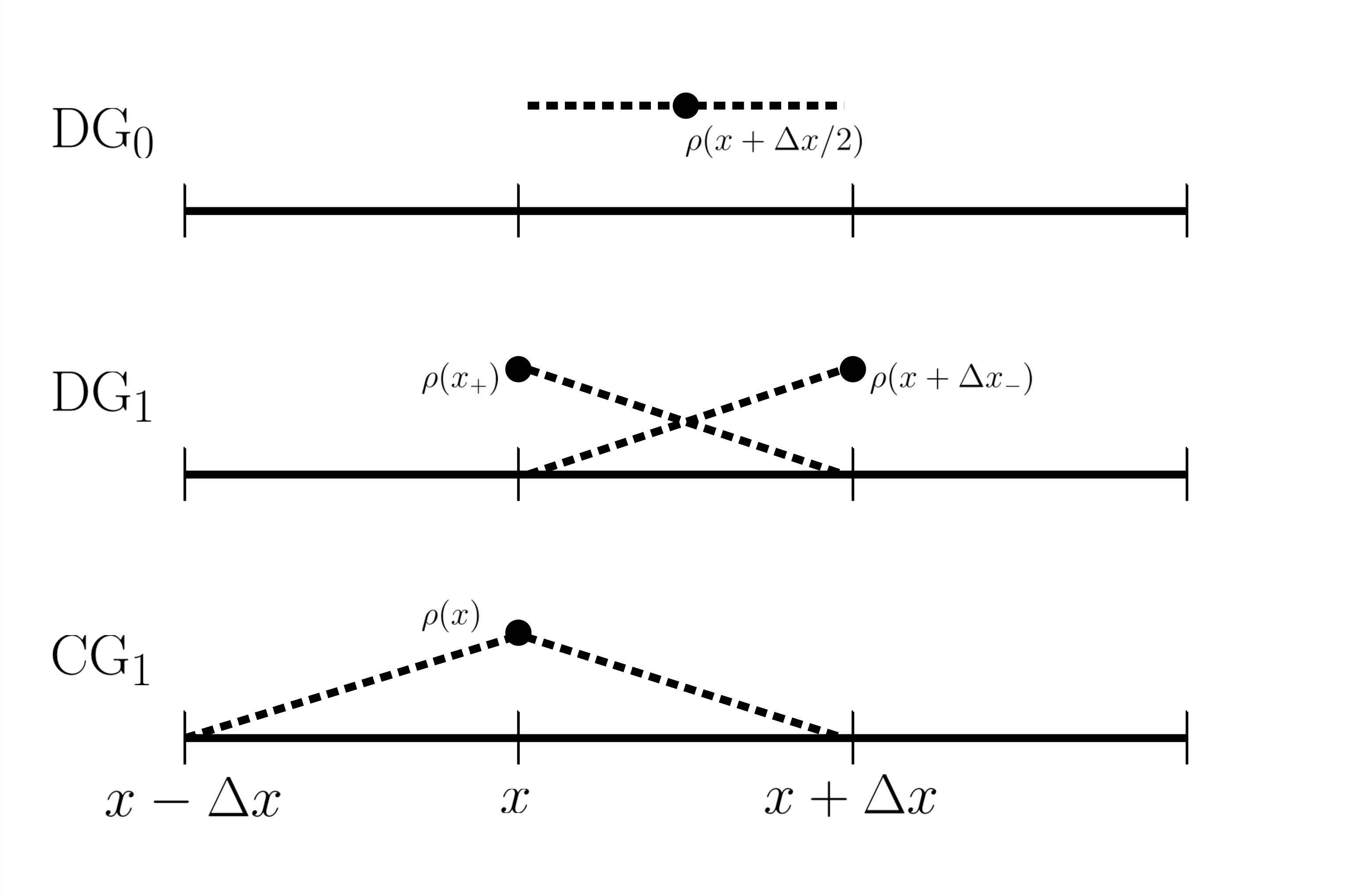
Three spaces are relevant to this analysis:
DG0, which is piecewise constant and whose DOFs are in the centre of cells;
CG1, which is continuous piecewise linear and has one DOF per cell at the cell boundary;
and DG1, which is linear within a cell but discontinuous between cells and has
two DOFs per cell – one at each cell boundary.
These spaces are shown in Figure 1.
3.2.1 Advection Operator
First we described the advection operator acting upon the -th mode of a function in . In each cell, the function can be described by two components: evaluation of the field at each cell boundary. For the advection, we use a simple upwinding scheme with a forward Euler time discretisation, within the framework of a three-step Runge-Kutta scheme. We describe the action of a single forward Euler step with the operator . This is determined by discretising the one dimensional advection equation with constant ,
| (3.14) |
for by integrating with the test function . This gives
| (3.15) |
where denotes the jump in field between the -th cell and the -th cell. Making the assumption that , and using that is piecewise linear, we can write down a representation of for the degrees of freedom on either side of a given cell:
| (3.16) |
We then obtain the full advection operator by using the three-step Runge-Kutta scheme outlined in [17]:
| (3.17) | ||||
| (3.18) | ||||
| (3.19) |
The overall advection operator is then
| (3.20) |
where is the identity operator. We omit the matrix representation of here for brevity.
3.2.2 Case A:
This represents the advection of density ,
or the velocity perpendicular to its direction.
The set of spaces
is .
Then, for a given cell and Fourier mode, the operators can be represented in
the following matrix forms
| (3.21) |
Combining these operators, the advection scheme for the -th mode of is then expressed as
| (3.22) |
Following the analysis through and writing gives a stability constant
| (3.23) |
3.2.3 Case B: with
In this case the set of spaces is . This describes advection of velocity parallel to its direction, or of potential temperature without bounding the final projection step. The operators can be represented by
| (3.24) |
where the projection operator has been determined by solving equation (2.4). The recovery operator is the identity, and since the injection and the projection are equivalent in this case the scheme acting upon becomes . Following through the analysis gives
| (3.25) |
3.2.4 Case C: with
For this case, the set of spaces are the same as in the second case. The only difference is that the projection operator is now . As , the interpolation is the identity, and . The operators are
| (3.26) |
which gives leads to the amplification factor
| (3.27) |
3.3 Critical Courant Numbers
The Courant-Friedrich-Lewy (CFL) criterion says that an
advection scheme with amplification factor
may not be stable.
The critical Courant number is the lowest Courant number
such that the amplification factor
is greater than unity.
We numerically measured the critical Courant numbers for the
three cases laid out in Section 3.2, and these
are displayed in Table 2.
Although case C has a significantly lower critical Courant
number, the intention is to run this scheme with a limiter
or with a subcycling time discretisation, allowing it
to be used at higher Courant numbers.
Instances of work using these kind of limiters are
[9] and [16].
Examples of critical Courant numbers for other upwinding schemes
can be found in Table 2.2 of [18].
The most relevant comparison that can be made from this
is to that of polynomials of degree 1 with a Runge-Kutta method of order 3,
which has a critical Courant number of 0.409.
A space of discontinuous linear polynomials has the same number of degrees of freedom
as a space of discontinuous constants but with half the grid size, and thus improvements
are made if the critical Courant number is more than twice that of the transport scheme for the
linear functions.
We do therefore observe that the critical Courant numbers for cases A and B are improvements
on the discontinuous upwinding scheme applied just to discontinuous linear functions.
| Case | A | B | C |
|---|---|---|---|
| 0.8506 | 0.9930 | 0.3625 |
4 Numerical Tests
The numerical implementation of this scheme was performed using the Firedrake software of [19], and relied heavily on the tensor product element functionality on extruded meshes, descriptions of which can be found in [11], [20] and [21].
4.1 Numerical Accuracy
To verify the numerical accuracy of the scheme, we performed
a series of convergence tests.
The aim is to find how the error due to advection changes
with the grid spacing .
We used tests that have an analytic solution
in the limit that , and compare the final
advected profile with the ‘true’ profile , which
is the analytic solution projected into the relevant function
space.
This gives an error (where denotes the norm) which is calculated for
the same problem at different
resolutions, and the errors are plotted as a function
of the grid spacing .
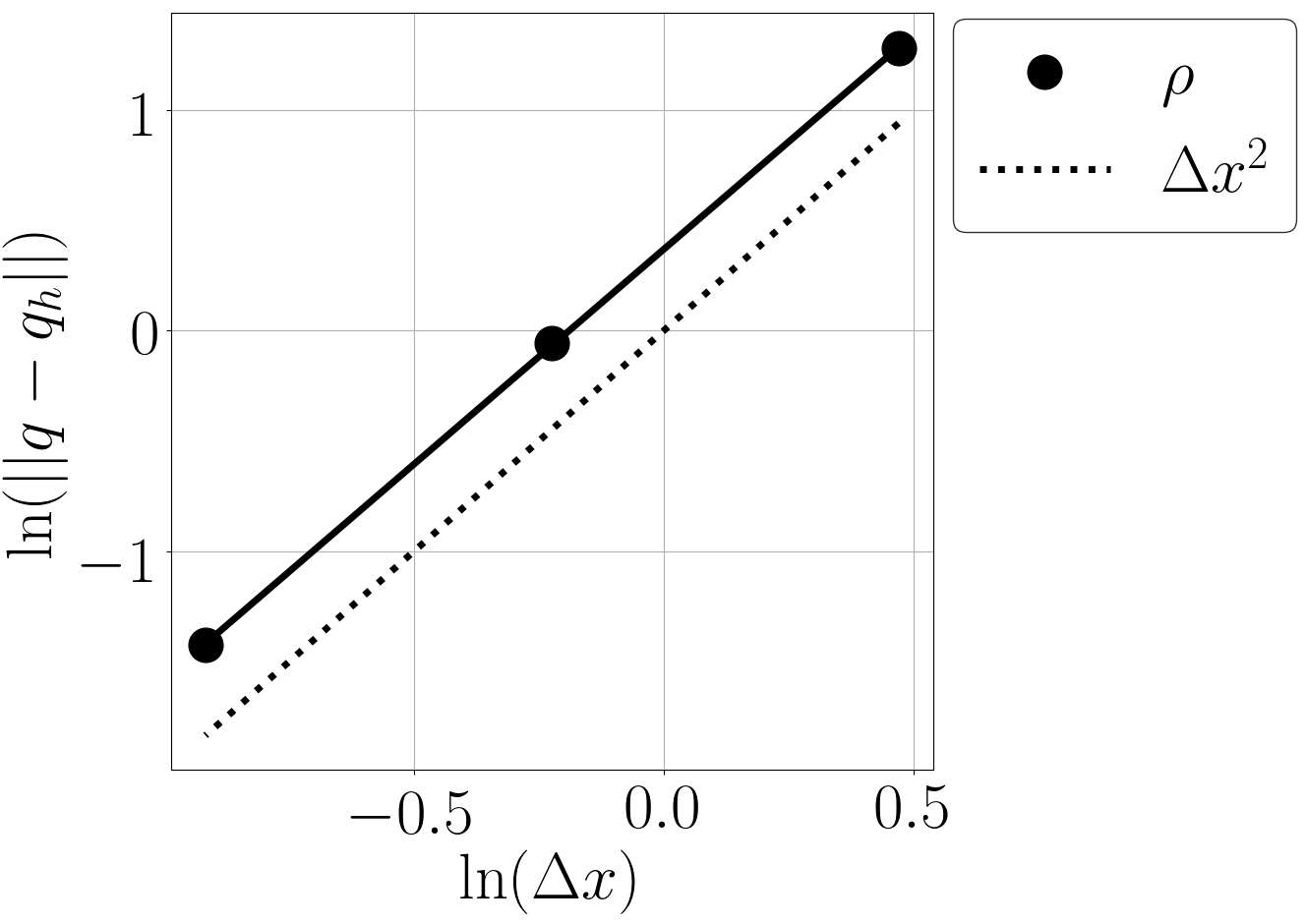
The order of the numerical accuracy is the number such that
, which can
measured from the slope of a plot of
against .
For simplicity, the tests we used are designed so that the ‘true’
profile is the same as the initial condition.
The initial conditions were obtained by pointwise evaluation
of the expressions into higher order fields (we used CG3).
These were then projected into the correct fields.
The advecting velocity used lay in the RT1 space.
To mimic how the scheme might be used in a numerical weather
model, we performed some of the tests on the different sets
of spaces laid out in Section 2.2
and the configurations described in Section
3.2.
Each set of spaces is labelled by the variable name in Table 1,
with
for the fields , , and given by
| (4.1) | ||||
| (4.2) | ||||
| (4.3) | ||||
| (4.4) |
where the bold font recognises that the space has vector valued nodes.
While the scheme labelled uses the projection operator
, the scheme labelled represents a moisture
variable, so uses the same spaces
as but the projection operator
and the vertex-based limiter of [16].
All tests solve the transport equation in the ‘advective’ form
of (2.1).
The first three tests involve advection around a 2D domain
representing a vertical slice that is periodic along
its side edges but rigid walls at the top and bottom.
The final test is performed over the surface of a sphere.
All the vertical slice tests use a domain of height and width
1 m and advect the profile with time steps of
s for a total time of s.
4.1.1 Rotational Convergence Test
The first test involves a rigid body rotation of a Gaussian profile around the centre of the domain. Using and as the horizontal and vertical coordinates, defining for m, m and using m, the initial condition used for all fields was
| (4.5) |
For the velocity variable, this initial profile was used for each component of the field. The advecting velocity is generated from a stream function via . Defining with m and m, the stream function used was:
| (4.6) |
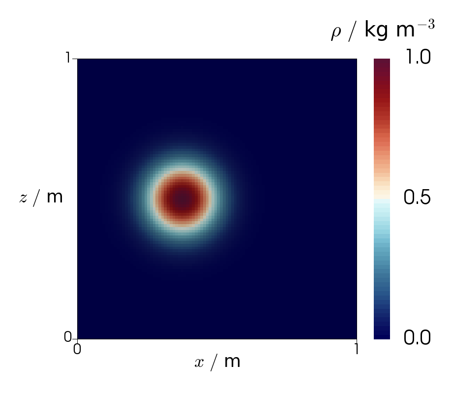
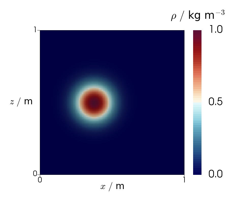
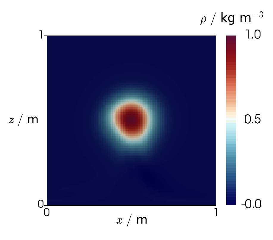
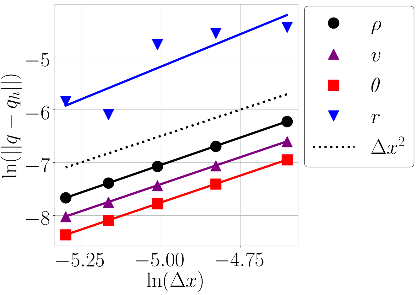
This is designed to be a rigid body rotation for , with no velocity for to prevent spurious noise being generated from the edge of the domain. The stream function and its derivative vary smoothly for . We use m and m, with , and . Results showing second order numerical accuracy can be found in Figure 4 (left). Initial and final fields for the density in the lowest resolution run ( m) are displayed in Figure 2.
4.1.2 Deformational Convergence Test
The second test is a more challenging convergence test, based on the deformational flow experiment described in [9]. The initial profiles were the same as used in the rotational advection test, but with m. The advecting velocity was that of [9]:
| (4.7) |
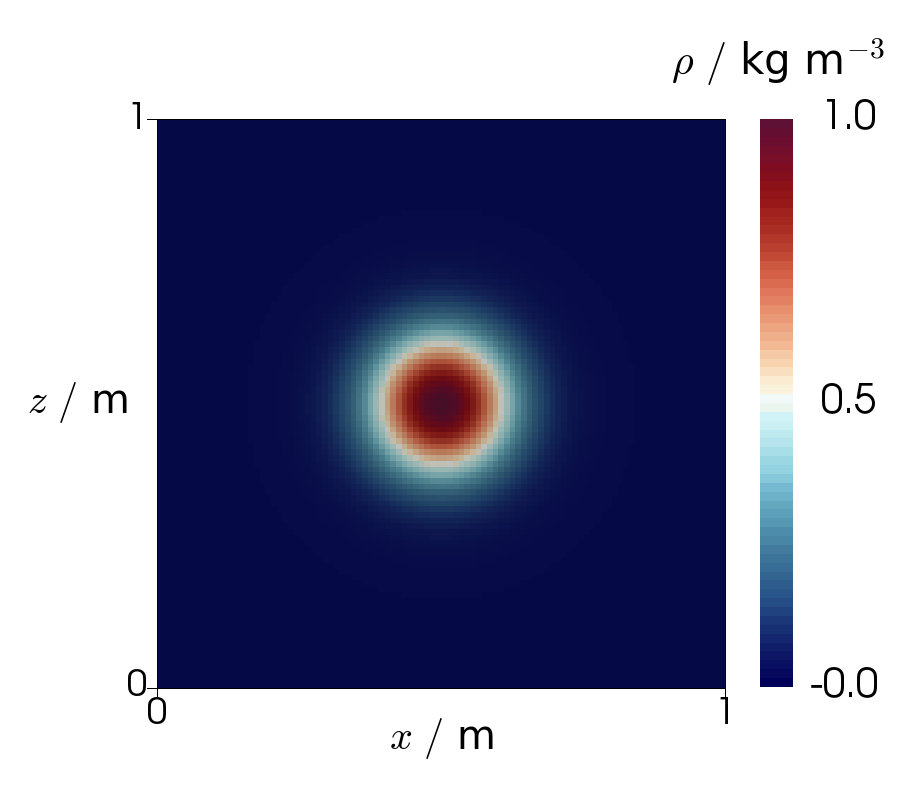
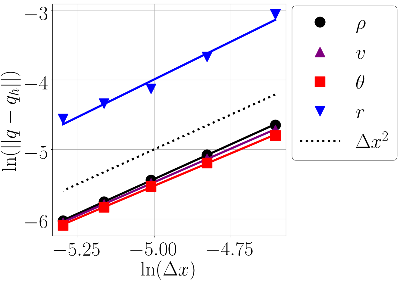
Figure 4 (right) plots the results of this test, with each variable measuring second order numerical accuracy. Initial and final fields for the density in the lowest resolution run ( m) are displayed in Figure 3.
4.1.3 Boundary Convergence Test
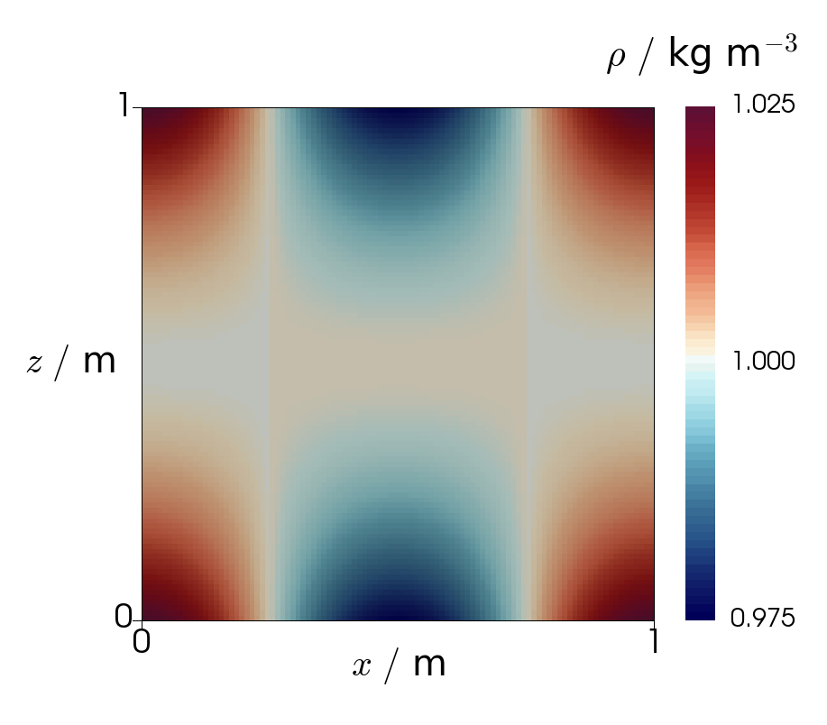
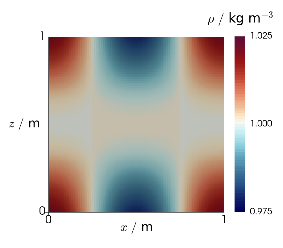
The third test was intended to investigate the integrity of the advection scheme at the boundaries of the domain. We use the following reversible flow, which squashes the advected material into the boundary before recovering it:
| (4.8) |
The initial condition was
| (4.9) |
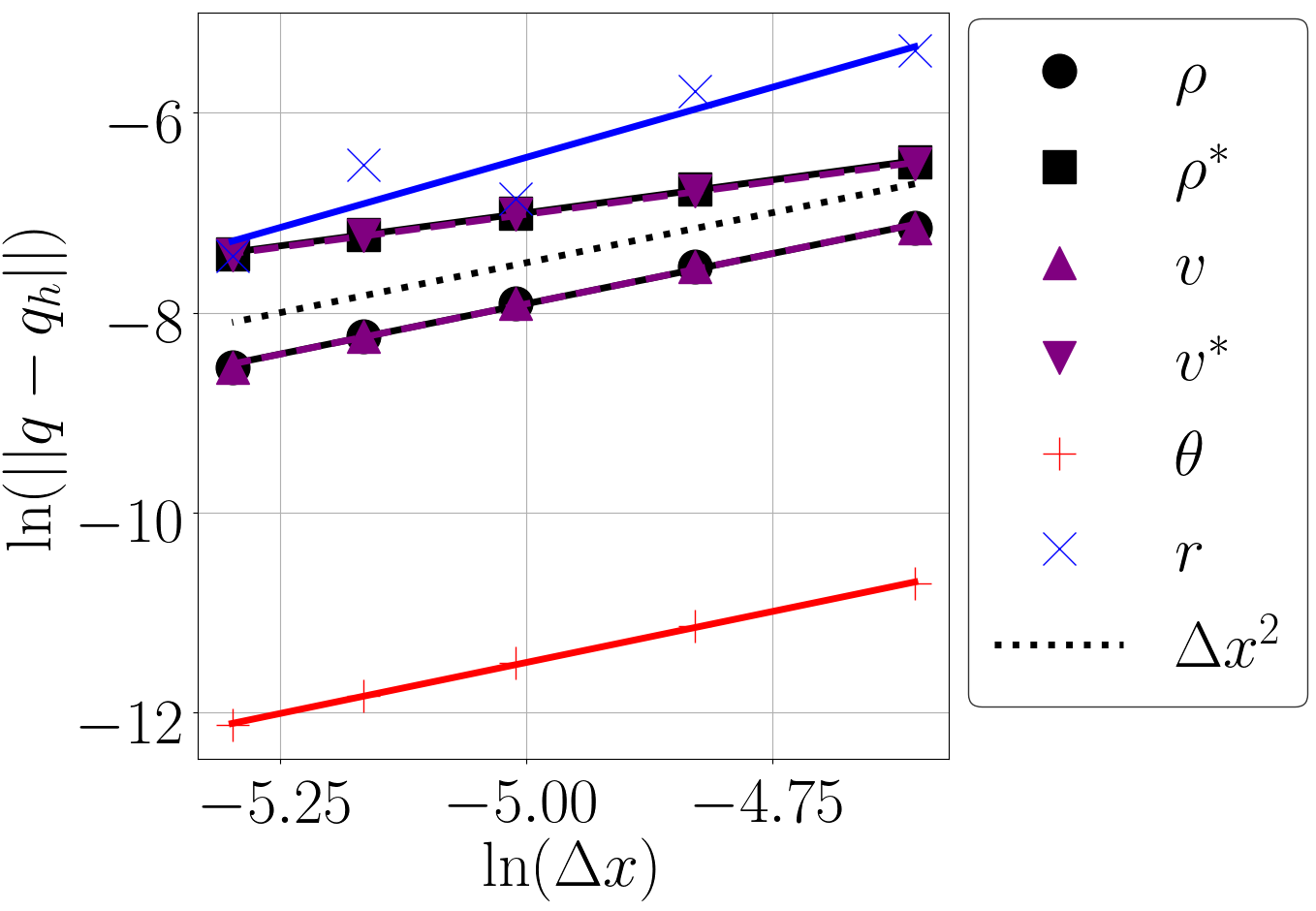
To see the effect of the extra recovery performed at the boundary described in Section 2.3, this extra recovery was turned off for the variables labelled with an asterisk. The results in Figure 7 (left) demonstrate that without doing extra recovery at the boundaries, the whole recovery process does not have second order numerical accuracy. Initial and final fields for the density in the lowest resolution run ( m) are displayed in Figure 5.
4.1.4 Spherical Convergence Test
The final convergence test was performed on the surface of a sphere. In this case we used a cubed sphere mesh of a sphere of radius 100 m. The advecting velocity field used was , for latitude and m s-1, which gave a constant zonal rotation rate about the sphere. We took time steps of s up to a total time of s so that the initial profile should be equal to the ‘true’ profile. The initial profile that we used was very similar to that used in the first test case of [22]:
| (4.10) |
where m and for latitude and longitude with and , and where is now given by
| (4.11) |
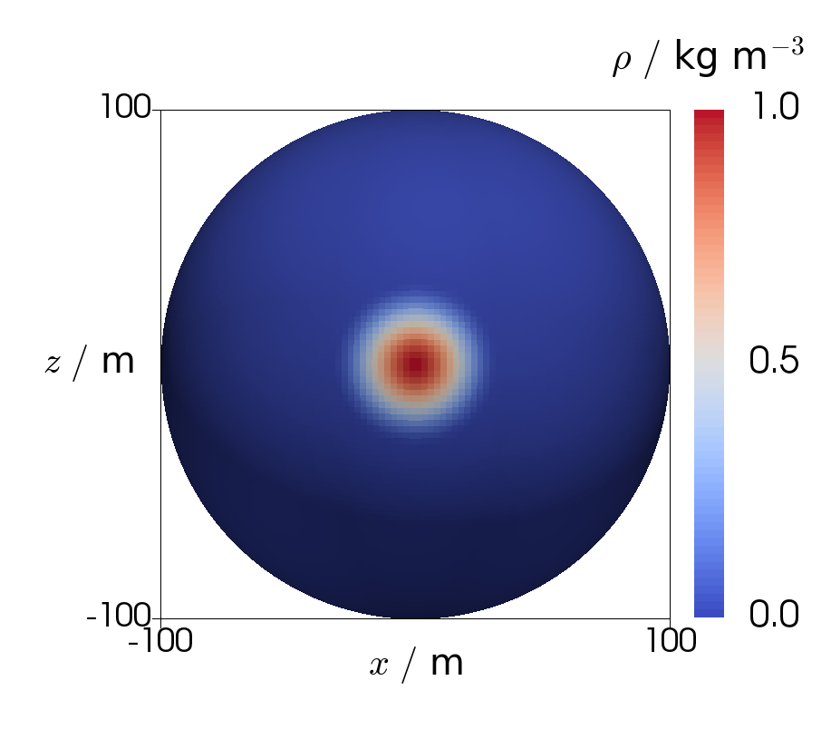
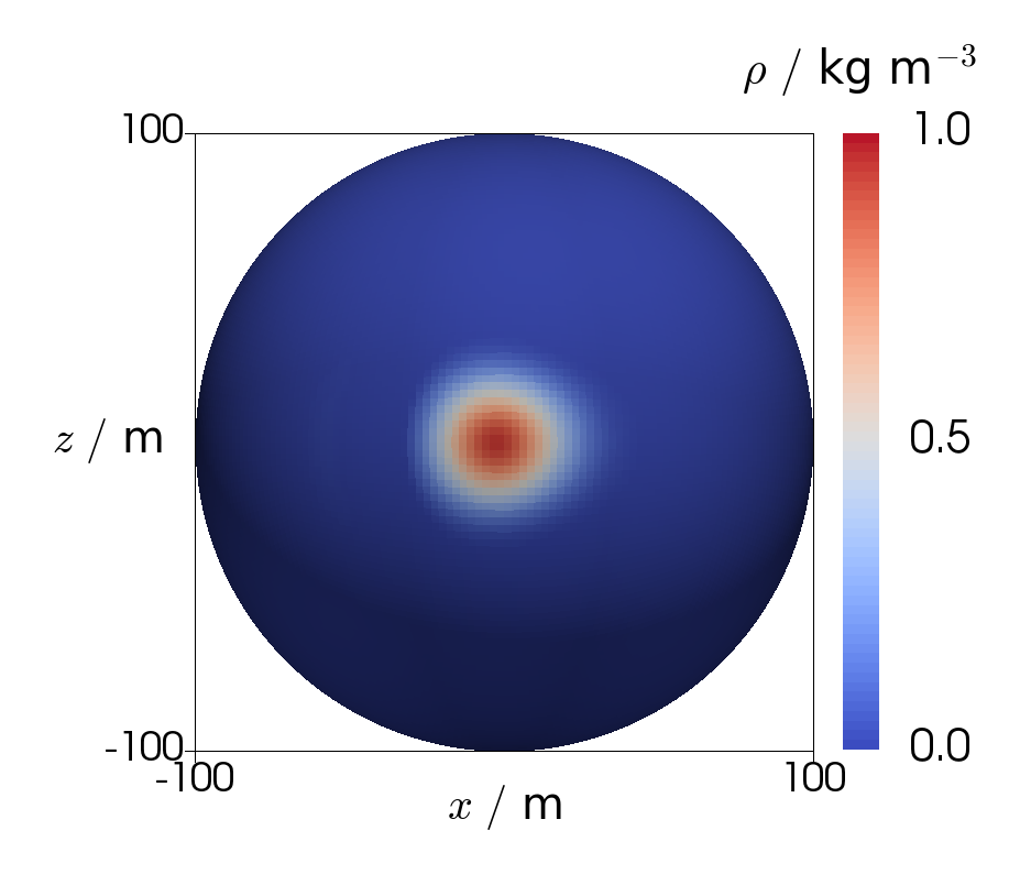
The errors of this test as a function of resolution are plotted in Figure 7 (right). This also appears to show second order accuracy. We found that at lower resolutions, the errors due to the advective scheme were obscured by those from the imperfect discretisation of the surface of the sphere. The initial and final fields of this test are plotted for the coarsest resolution in Figure 6.
4.2 Stability
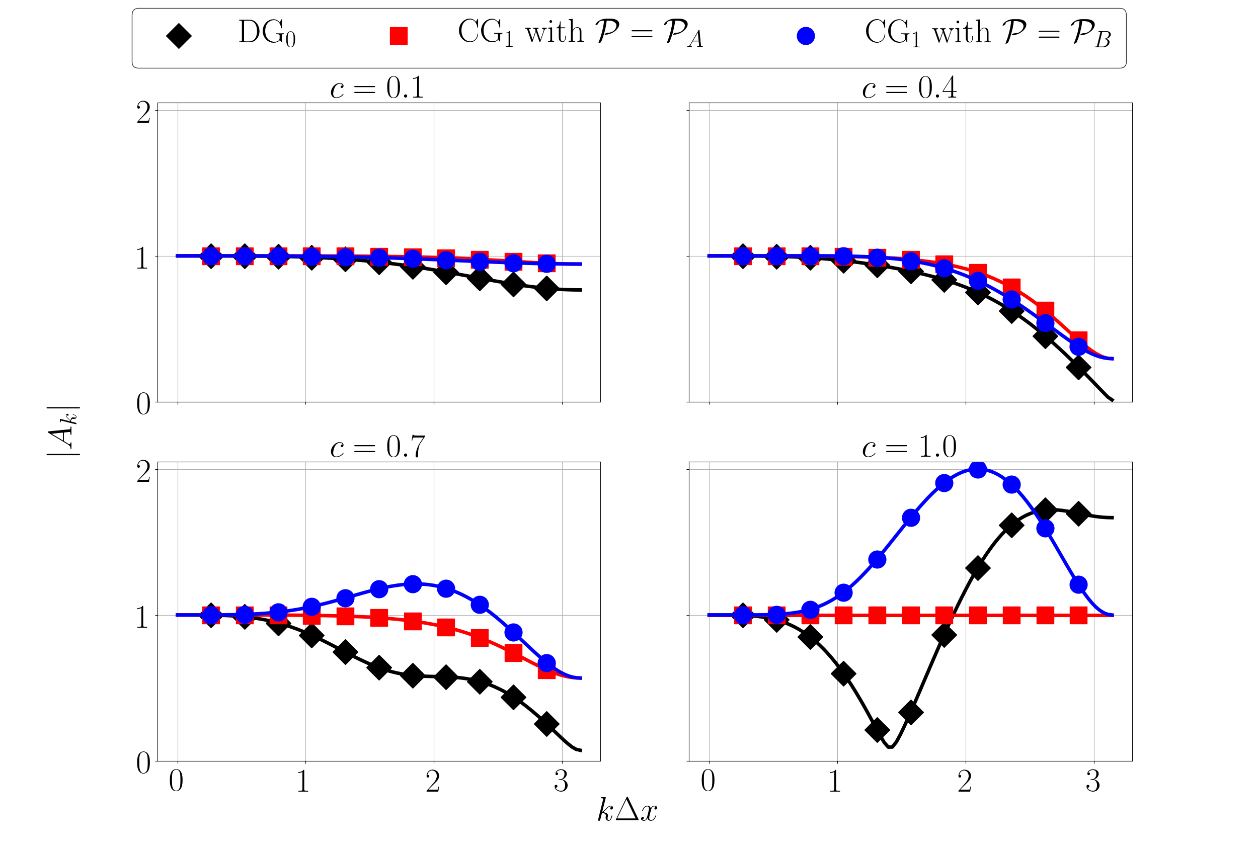
We tested the formulas (3.23), (3.25)
and (3.27)
by advecting sine and cosine waves for each of the cases defined.
The domain used was a square vertical slice of length 120 m
with grid spacing m.
The amplification factor for a given wavenumber and Courant
number was measured by advecting a sine and cosine wave
of wavenumber by a constant horizontal velocity
for a single time step of s.
As before, the domain had periodic boundary conditions on the
vertical walls.
The amplification factor was then found by measuring the
amplitude of the sine and cosine components after the first time
step.
This was done for several values of .
The measured values are compared with those from the formula
in Figure 8
which shows agreement for each of the cases considered in
Section 3.2.
4.3 Limiting
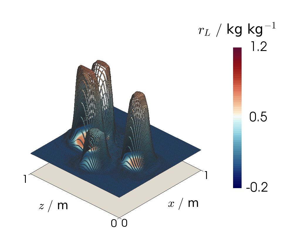
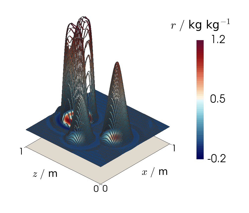
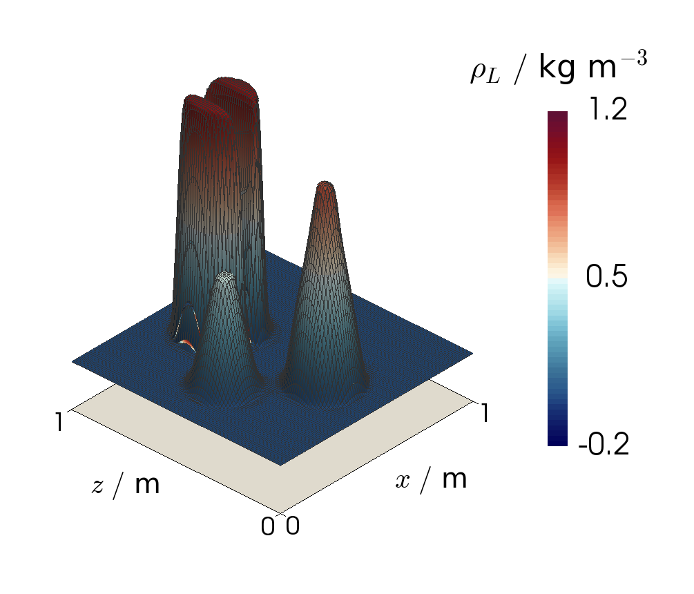
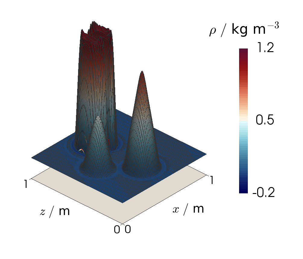
The efficacy of the limiting scheme was tested by using the LeVeque slotted-cylinder, hump, cone set-up originally defined in [23] and used in both [16] and [9]. The advected field was initialised lying with this condition, lying in the space to mimic moisture variables, before a solid-body rotation was completed. This was performed for the bounded case of the scheme defined in Section 2, using the projection operator and the vertex-based limiter of [16] for the advection. The resulting field is shown in Figure 9 where it is also compared to the rotation of a field in the space, using the same limited advection scheme, but without the ‘recovered’ parts of the scheme. The field does indeed remain bounded, suggesting that the limiter has worked well.
5 Compressible Euler Model
We have used this advection scheme in a numerical model of the compressible Euler equations. The continuous equations we used are
| (5.1) | |||
| (5.2) | |||
| (5.3) | |||
| (5.4) |
where with
m s-2 is the uniform gravitational
acceleration towards the Earth’s surface,
J kg-1 K-1 is the specific heat capacity
at constant pressure of a dry ideal gas,
J kg-1 K-1 is the specific gas constant of a
dry ideal gas,
and is the Exner pressure, found at reference pressure
hPa.
The general strategy to solve these equations is based
upon that used in the UK Met Office Endgame model,
and is very similar to that described in
[8], which discretised the Boussinesq
equations.
The overall structure of our model
can be described by the performance of various operations
to the state variables, which we denote together by
.
In a time step, the first stage is to apply a ‘forcing’
to , the details of which are explained
below.
At this point the algorithm enters an outer iterative loop, in which
an advecting velocity is determined, and an
advection step is performed by an advection operator
.
There is then an inner loop, in which the forcing is reapplied
and a residual is calculated between the newly forced state
and the best estimate for the state at the next time step.
The state is corrected by solving a linear problem
(here we denote the linear operator by )
for the residual.
The scheme is balanced between being explicit and implicit
by the off-centering parameter , which we will take to be 1/2.
This process is summarised by the following pseudocode:
-
1.
FORCING:
-
2.
SET:
-
3.
OUTER:
-
(a)
UPDATE:
-
(b)
ADVECT:
-
(c)
INNER:
-
i.
FIND RESIDUAL:
-
ii.
SOLVE: for
-
iii.
INCREMENT:
-
i.
-
(a)
-
4.
ADVANCE TIME STEP:
In our case, the forcing operator acts only upon the velocity. It is the solution to the following problem:
| (5.5) |
where is the domain, is the set of all interior facets, the angled brackets denote
the average value on either side of a facet and
is the function space
in which the velocity field lies.
The advection operators use the scheme defined in Section
2 with as the simple upwinding
and three-step Runge-Kutta method described in
Section 3.2.
The spaces used in the recovered scheme are listed in
Section 2.2.
We do not use any limiting strategy for , and use the projection operator in all schemes.
Finally, the strategy for the linear solve step is to first
analytically eliminate .
The resulting problem for and defines
the operator , which we solve using a Schur complement
preconditioner.
Then is reconstructed from the result.
5.1 Rising Bubble Test Case
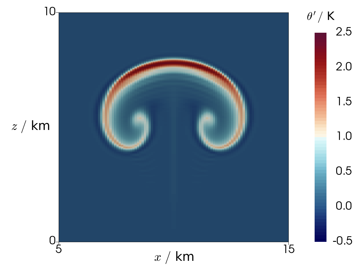
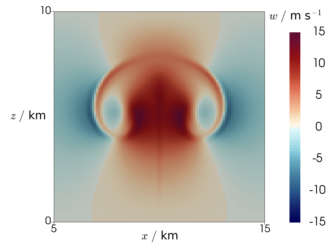
Here we show some results of using the recovered space advection scheme within a full model of the compressible Euler equations in the context of a vertical slice model. The example test case that we use is the dry bubble test of [24]. The initial state is K and zero velocity everywhere, while is determined via from solving for hydrostatic balance using the procedure described in [6]. The following perturbation to was then applied:
| (5.6) |
so that , with
| (5.7) |
where = 10 km, 2 km. In the model used in [24], the Exner pressure is a prognostic variable, rather than the density . To ensure that our initial pressure is unchanged by the perturbation, we found the initial density state by solving for :
| (5.8) |
where is the function space that lives in, and and are the hydrostatically balanced background states. The domain used had a width of 20 km and a height of 10 km. The top and bottom boundaries had rigid lid boundary conditions () whilst there were periodic boundary conditions on the left and right sides. The perturbed potential temperature field at the final time s is shown in Figure 10 for a simulation with grid spacing m and time steps of = 1 s. Although there is good agreement between the fields shown in Figure 10 and those presented in [24], there are some visible errors in the solution: chiefly some ringing artifacts surrounding the mushroom-shaped perturbation that develops in the field. In the authors’ experience, such numerical simulations of rising or sinking thermals can often exhibit instability at the leading edge of the moving bubble, capturing an inherent physical instability. In this case, the underlying equations may have multiple solutions and the numerical solution may not converge to one as the resolution is refined.
6 Summary and Outlook
We have presented a new ‘recovered’ advection scheme for use in numerical weather prediction models. This scheme is a form of the embedded DG advection described in [9], but in which higher-degree spaces are recovered via averaging operators, as described in [12]. It is intended for use with the compatible finite element set-up laid out in [2], and in particular can be used with the zeroth-degree set of spaces. With these spaces, the scheme has second-order numerical accuracy. We have also presented a bounded version of this scheme, which can be used for moisture variables to preserve monotonicity or to prevent negative values. Stability properties of the scheme have also been provided. Future work should extend this scheme to cover vector functions that lie in curved domains. This will require careful averaging of vectors that lie in different tangent spaces.
Acknowledgements
TMB was supported by the EPSRC Mathematics of Planet Earth Centre for Doctoral Training at Imperial College London and the University of Reading. CJC was supported by EPSRC grant EP/L000407/1, while JS was supported by the EPSRC EP/L000407/1 and NERC NE/R008795/1 grants. The authors would like to thank the developers of the Firedrake software which was used extensively for this work, and in particular Thomas H. Gibson who wrote the original piece of code for the recovery operator. The authors are also grateful to the two anonymous reviewers whose constructive feedback was useful in the revision of this paper. Any mistakes, however, belong to the authors.
References
- [1] A. Staniforth and J. Thuburn, “Horizontal grids for global weather and climate prediction models: a review,” Quarterly Journal of the Royal Meteorological Society, vol. 138, no. 662, pp. 1–26, 2012.
- [2] C. J. Cotter and J. Shipton, “Mixed finite elements for numerical weather prediction,” Journal of Computational Physics, vol. 231, no. 21, pp. 7076–7091, 2012.
- [3] A. Staniforth, T. Melvin, and C. Cotter, “Analysis of a mixed finite-element pair proposed for an atmospheric dynamical core,” Quarterly Journal of the Royal Meteorological Society, vol. 139, no. 674, pp. 1239–1254, 2013.
- [4] C. J. Cotter and J. Thuburn, “A finite element exterior calculus framework for the rotating shallow-water equations,” Journal of Computational Physics, vol. 257, pp. 1506–1526, 2014.
- [5] A. T. McRae and C. J. Cotter, “Energy-and enstrophy-conserving schemes for the shallow-water equations, based on mimetic finite elements,” Quarterly Journal of the Royal Meteorological Society, vol. 140, no. 684, pp. 2223–2234, 2014.
- [6] A. Natale, J. Shipton, and C. J. Cotter, “Compatible finite element spaces for geophysical fluid dynamics,” Dynamics and Statistics of the Climate System, vol. 1, no. 1, 2016.
- [7] J. Shipton, T. Gibson, and C. Cotter, “Higher-order compatible finite element schemes for the nonlinear rotating shallow water equations on the sphere,” Journal of Computational Physics, vol. 375, pp. 1121–1137, 2018.
- [8] H. Yamazaki, J. Shipton, M. J. Cullen, L. Mitchell, and C. J. Cotter, “Vertical slice modelling of nonlinear Eady waves using a compatible finite element method,” Journal of Computational Physics, vol. 343, pp. 130–149, 2017.
- [9] C. J. Cotter and D. Kuzmin, “Embedded discontinuous Galerkin transport schemes with localised limiters,” Journal of Computational Physics, vol. 311, pp. 363–373, 2016.
- [10] D. N. Arnold and A. Logg, “Periodic table of the finite elements,” SIAM News, vol. 47, no. 9, p. 212, 2014.
- [11] A. T. McRae, G.-T. Bercea, L. Mitchell, D. A. Ham, and C. J. Cotter, “Automated generation and symbolic manipulation of tensor product finite elements,” SIAM Journal on Scientific Computing, vol. 38, no. 5, pp. S25–S47, 2016.
- [12] E. H. Georgoulis and T. Pryer, “Recovered finite element methods,” Computer Methods in Applied Mechanics and Engineering, vol. 332, pp. 303–324, 2018.
- [13] V. A. Titarev and E. F. Toro, “Ader: Arbitrary high order godunov approach,” Journal of Scientific Computing, vol. 17, no. 1-4, pp. 609–618, 2002.
- [14] B. Van Leer and S. Nomura, “Discontinuous galerkin for diffusion,” in 17th AIAA Computational Fluid Dynamics Conference, p. 5108, 2005.
- [15] O. A. Karakashian and F. Pascal, “Convergence of adaptive discontinuous Galerkin approximations of second-order elliptic problems,” SIAM Journal on Numerical Analysis, vol. 45, no. 2, pp. 641–665, 2007.
- [16] D. Kuzmin, “A vertex-based hierarchical slope limiter for p-adaptive discontinuous Galerkin methods,” Journal of computational and applied mathematics, vol. 233, no. 12, pp. 3077–3085, 2010.
- [17] C.-W. Shu and S. Osher, “Efficient implementation of essentially non-oscillatory shock-capturing schemes,” Journal of Computational physics, vol. 77, no. 2, pp. 439–471, 1988.
- [18] B. Cockburn and C.-W. Shu, “Runge–kutta discontinuous galerkin methods for convection-dominated problems,” Journal of scientific computing, vol. 16, no. 3, pp. 173–261, 2001.
- [19] F. Rathgeber, D. A. Ham, L. Mitchell, M. Lange, F. Luporini, A. T. McRae, G.-T. Bercea, G. R. Markall, and P. H. Kelly, “Firedrake: automating the finite element method by composing abstractions,” ACM Transactions on Mathematical Software (TOMS), vol. 43, no. 3, p. 24, 2017.
- [20] G.-T. Bercea, A. T. McRae, D. A. Ham, L. Mitchell, F. Rathgeber, L. Nardi, F. Luporini, and P. H. Kelly, “A structure-exploiting numbering algorithm for finite elements on extruded meshes, and its performance evaluation in firedrake,” arXiv preprint arXiv:1604.05937, 2016.
- [21] M. Homolya and D. A. Ham, “A parallel edge orientation algorithm for quadrilateral meshes,” SIAM Journal on Scientific Computing, vol. 38, no. 5, pp. S48–S61, 2016.
- [22] D. L. Williamson, J. B. Drake, J. J. Hack, R. Jakob, and P. N. Swarztrauber, “A standard test set for numerical approximations to the shallow water equations in spherical geometry,” Journal of Computational Physics, vol. 102, no. 1, pp. 211–224, 1992.
- [23] R. J. LeVeque, “High-resolution conservative algorithms for advection in incompressible flow,” SIAM Journal on Numerical Analysis, vol. 33, no. 2, pp. 627–665, 1996.
- [24] G. H. Bryan and J. M. Fritsch, “A benchmark simulation for moist nonhydrostatic numerical models,” Monthly Weather Review, vol. 130, no. 12, pp. 2917–2928, 2002.