Empirical Effects of Dynamic Human-Body Blockage in 60 GHz Communications
Abstract
The millimeter wave (mmWave) bands and other high frequencies above 6 GHz have emerged as a central component of Fifth-Generation (5G) cellular standards to deliver high data rates and ultra-low latency. A key challenge in these bands is blockage from obstacles, including the human body. In addition to the reduced coverage, blockage can result in highly intermittent links where the signal quality varies significantly with motion of obstacles in the environment. The blockages have widespread consequences throughout the protocol stack including beam tracking, link adaptation, cell selection, handover and congestion control. Accurately modeling these blockage dynamics is therefore critical for the development and evaluation of potential mmWave systems. In this work, we present a novel spatial dynamic channel sounding system based on phased array transmitters and receivers operating at 60 GHz. Importantly, the sounder can measure multiple directions rapidly at high speed to provide detailed spatial dynamic measurements of complex scenarios. The system is demonstrated in an indoor home-entertainment type setting with multiple moving blockers. Preliminary results are presented on analyzing this data with a discussion of the open issues towards developing statistical dynamic models.
I Introduction
Since the inception of cellular communications systems, providers have faced an ever-increasing demand for data. In recent years, the impending capacity crunch has forced the many stakeholders to explore higher frequency bands where more spectrum is available and harness them for mobile communication [1]. These extremely high frequencies include the millimeter wave bands, which formally comprise the range of 30 to 300 GHz. These bands, along with other frequencies above 6 GHz, are now considered the primary vehicle for enabling the extremely high throughputs of bandwidth-hungry applications and services in fifth-generation (5G) mobile networks.
However, the design and deployment of mmWave communication systems present several unique challenges arising from the relatively unfavorable radio wave propagation at these frequencies. Most significantly, mmWave signals are highly susceptible to blockage. Compared to signals transmitted at lower (e.g., microwave) frequencies, mmWave transmissions simply cannot penetrate many common objects and building materials. Similarly, the human body, the subject of this work, can typically result in 20 dB of attenuation as demonstrated later in this article – much greater than at lower frequencies.
In addition to loss in coverage, blockage results in another equally challenging problem: channel dynamics. Due to blockage, mmWave signal strength can vary rapidly with any motion relative to obstacles in the environment. For example, moving behind buildings, changes in the orientation of a handset or the location of a body or hand blocker may all cause fast and significant large-scale fading. These dynamics have a wide-ranging impact throughout the protocol stack including beam tracking, link adaptation, channel feedback at the physical layer, as well as Transmission Control Protocol (TCP) and end-to-end application performance. While there have been extensive studies of blockage in the mmWave bands, many of these works have been limited to static scenarios. For example, there are numerous studies for penetration loss measurements of various materials, as well as measurement campaigns in outdoor settings for deriving statistical path loss and coverage models with fixed receiver locations.
Understanding channel dynamics in realistic time-varying blockage scenarios is more complicated. Most importantly, mmWave transmissions are inherently directional. To overcome the high isotropic path loss, mmWave signals will be transmitted and received in narrow beams formed by electrically steerable antenna arrays. Due to scattering and reflections, there are often multiple viable communication paths in addition to the line-of-sight (LOS) links. Hence, if a current mmWave path is suddenly blocked, ongoing communication can be steered to an alternate path from the same serving cell or an alternate cell to maintain the Quality of Service/Experience [2]. MmWave blockage models must therefore describe the joint dynamics of these paths to properly assess such procedures including beam tracking, multi-connectivity, and handover.
In this article, we begin with an overview of blockage modeling techniques which view blockage from a Radio Frequency (RF) theory perspective [3], and those which seek to develop statistical models and methodologies for simulations involving mmWave blockage [4]. These statistical models often rely on ray-tracing based studies instead of measured data due to the difficulty of performing these measurements.
To ensure that there is no gap between these blockage models and the true statistical nature of human blockage, NYU WIRELESS has developed a 60 GHz measurement system using two phased arrays. Importantly, the system can measure the channel characteristics in multiple directions almost simultaneously. We report measurements in an indoor, home entertainment-type setting with multiple moving blockers and discuss some preliminary efforts aimed at deriving statistical characterizations of blockage dynamics from these measurements.
II Overview of Blockage Models
Before describing blockage models, it is useful to consider a typical human-body blockage event. Fig. 1 presents a trace of such an event from our measurements discussed in detail below. The figure shows the attenuation versus time for the LOS component. Blockage models seek to characterize the statistics of various key parameters such as the attenuation level, the duration of the blockage, as well as the fading and rise time.
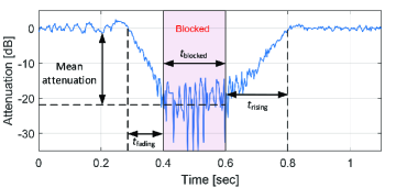
We can see that the impact of human-body blockage on the radio link can be severe. In the trace of Fig. 1, there is a more than 20 dB attenuation for a duration of seconds. Furthermore, before and after the link is blocked, there are regions and , where the signal strength first decreases as the blocker begins to obstruct the LOS path and then rises as the blocker moves away. These effects alone can influence the quality of a mmWave connection. For 5G wireless systems requiring low latency, such blockage durations are critical and must be mitigated by beam steering antenna arrays. If the LOS signal is blocked, the link can be maintained by switching to an alternative path.
II-A Blockage Studies Extending RF Theory
Many early papers on mmWave blockage focused on 60 GHz due to the standardization efforts behind IEEE 802.11ad and beyond [3], [4]. More recently, with the increasing interest in mmWave for 5G there have been a growing number of contributions that targeted other frequencies, such as 28 and 73 GHz. The authors of [5] reported a series of measurements performed with a single-input single-output (SISO) channel sounder operating at 73 GHz. Two horn antennas were pointed directly at each other to yield a channel that was dominated by a single LOS component, where a human blocker walked through the link at varying distances between the transmitter (TX) and the receiver (RX). The resulting data was utilized to verify and extend the well-known double knife edge diffraction (KED) model to allow its use with directional antennas at mmWave frequencies. In this model, the attenuation due to a screen between the TX and the RX is computed analytically, requiring precise knowledge of the TX, RX, and screen locations. In addition to the double KED model, other models have received attention such as multiple KED and uniform theory of diffraction. As argued in [6], alternative blockage models may under- or overestimate attenuation; thus, measurements are needed in order to accurately characterize human-body blockage.
II-B mmWave Blockage Models for Simulation Purposes
Geometry based blockage models are a very common approach which allows the simulation to capture the effects of blockers moving throughout the environment. As noted earlier, the question is whether or not the locations and behavior of these blockers can be accounted for accurately. Despite these concerns, these types of models are widespread and can be very useful in the appropriate circumstances.
The 3rd Generation Partnership Project (3GPP) channel model for frequencies from 0.5 to 100 GHz [7] includes blockage as an add-on feature. The blockers are distributed randomly within the environment in a way that is dependent upon the scenario under simulation. To evaluate attenuation due to blockage, there are two methods available. The first is a simplified model, which remains computationally efficient, while the second is a more intensive but realistic calculation that models each blocker as a screen and then follows the KED theory to calculate the attenuation due to blockage.
The METIS initiative [8] also utilizes geometry-based blockage modeling with screens similar to 3GPP. All the considered screens are vertical and oriented perpendicular to the line connecting the TX and the RX. For sparse distributions of blockers, METIS proposes to sum the losses due to each of the screens, whereas in denser distributions a more sophisticated technique based on the Walfisch-Bertoni model is employed to determine the effects of multiple blockers.
In [9], the authors perform an extensive simulation of mmWave blockage in a vehicle-to-infrastructure (V2I) scenario. Vehicles are randomly dropped into an environment which has base stations located at street corners. The effects of large blocking vehicles such as buses and trucks are considered and important figures such as coverage probability are derived analytically and verified via numerical simulations. Using this framework, the authors were able to uncover some interesting insights, such as the fact that blockage can be considered insignificant for V2I scenarios with multiple-lanes as opposed to a single-lane roadway.
II-C Common Measurement Methods
One common method to study dynamic blockage is by employing a combination of physical measurements and ray-based simulations. The measurement systems typically fall into several categories: (i) fixed horn or patch antennas possibly with mechanical steering, (ii) quasi-omni antennas, and (iii) MIMO measurement systems with a limited number of antennas. Horn antennas provide excellent spatial filtering, which makes them well suited for many types of channel measurements. However, this spatial filtering is a double-edged sword when it comes to studying channel dynamics where one would like to simultaneously measure the channel across all multipath components that are available. Because human blockage is a process that unfolds over timescales on the order of milliseconds, it is impossible to rotate a horn antenna quickly enough to perform measurements over all of these paths.
This problem is partially resolved by utilizing antennas with an omnidirectional pattern, where it is indeed possible to simultaneously measure blockage of different multipath components. However, this capability comes at the cost of spatial information. Multipath components are identified solely by the different times at which they arrive at the receiver. As will be discussed later, phased array systems can bridge the gap between these different types of measurement systems.
Another consideration for a blockage measurement campaign is whether or not the blockers should be aware of the experiment and follow predefined paths, or whether they should be people moving throughout an environment in a completely unbiased manner. For measurements seeking to verify RF theory it makes sense to have the blockers follow simple paths for repeatability [5], whereas for measurements that are being used to understand the statistics of blockage it is preferable to have the blockers be unaware of the experiment [10]. A potential third option is to have blockers follow predefined paths that are designed to mimic the motion of ordinary people.
III Blockage Measurement Methodology
III-A Experimental Setup
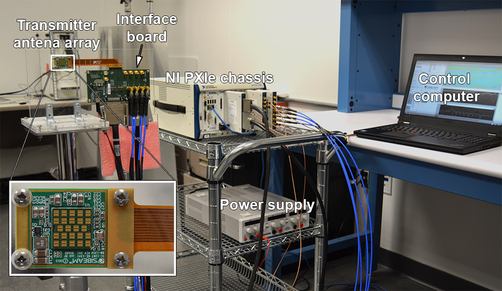
To address the limitations of common measurement techniques discussed earlier, NYU WIRELESS has constructed a setup that utilizes SiBeam 60 GHz phased antenna arrays at both the TX and RX [11]. Each transceiver array consists of 12 steerable TX elements and 12 steerable RX elements. The array has a steerable range of approximately in the azimuth plane with a peak directional gain of 23 dBi. This system enables directional measurements to be performed similar to studies that relied on mechanically rotated horn antennas, but is additionally capable of switching from one angle of arrival/departure (AoA/AoD) to another with microsecond latency – fast enough to keep up with human blockage events. The SiBeam phased array can electronically alter its pointing angle by applying a weight vector which defines the relative phases applied to the elements of the antenna array.
A crucial drawback of phased arrays is that the radiation patterns that can be achieved are often of much poorer quality than those of horn antennas. For example, in [12] the authors present simulated antenna patterns for the same arrays that are used in this work. They note that the half-power beamwidths are typically around and in some cases the mainlobe and sidelobe are nearly at the same level, particularly as the mainlobe gets farther away from the boresight. Luckily, different multipath components can still be discriminated via the transmission of a wideband sequence which separates different arriving multipath components in the channel. This system can be thought of as a middle ground between horn antennas which provide excellent spatial resolution but can only measure a single multipath component, and omnidirectional measurements which provide no spatial information and therefore rely entirely on delay to distinguish different multipath components.
Our system uses two codebooks of 12 predefined antenna weight vectors that allow for the TX and RX array to be scanned over a dozen of distinct angles of arrival/departure with an approximate range of coverage of in the azimuth plane. Each array is supported by a National Instruments PCI eXtenstions for Instrumentation (PXIe) chassis. Fig. 2 displays the TX component of the system. The chassis contains several Field Programmable Gate Arrays (FPGAs) as well as Input/Output (I/O) modules that allow them to interface with the array. These FPGAs implement all of the necessary signaling to control the arrays during a measurement as they rapidly scan over the azimuth plane. Cables connecting the TX and the RX chassis ensure that these remain synchronized throughout an experiment.
III-B Measurement Procedure
In each measurement, we collect hundreds of thousands of complex-valued channel impulse response (CIR) samples over a period of about 5 seconds. To perform a scan over all of the possible combinations of AoA and AoD, the TX will first apply one weight vector to the array, and the RX will cycle through its 12 weight vectors and acquire a CIR for each. The TX will then advance to the next weight vector in its codebook, with the RX again cycling through its entire codebook. A single scan of all 144 AoA/AoD combinations takes less than one millisecond, and this scan is repeated approximately every 3 milliseconds.
The duration of a single scan is short relative to the speed of a moving blocker; thus, we can assume that all CIRs captured during one scan experience the same blockage profile. In other words, one can conclude that these CIRs are captured ‘almost’ simultaneously. This is a crucial feature of our system which separates it from other similar setups that can only examine blockage over a single path at a time.
III-C Indoor Blockage Measurements
To evaluate the effects of human-body blockage in a characteristic in-home streaming/gaming scenario, a measurement campaign was conducted in a room on the NYU campus with furnishings that mimicked a typical living room. The TX was located at a height of 1 m beneath a wall-mounted TV to model a set-top box or similar device located as part of an entertainment center, while the RX was located 4 m away in front of a couch to represent a seated user. While the measurement system was continuously scanning, human blockers moved around the room at typical walking speeds following the paths indicated in Fig. 3.

Trials 1, 2, and 3 featured a single human blocker walking perpendicular to the LOS path between the TX and the RX. This simple blocker motion serves as a useful baseline and provides a good opportunity to compare with other studies such as the one in [13]. Trial 4 comprised multiple blockers attempting more ‘natural’ paths as if they were entering/exiting the room or moving from one seat to another. This trial was repeated with the number of blockers varied from 1 to 3 in order to examine the effects associated with the density of blockers. Finally, all trials were performed with the arrays turned in the azimuth plane. This allowed the experiments to better capture the non-LOS (NLOS) component reflected off the walls of the room.
This setup was chosen because it represents a scenario of significant interest (wireless virtual reality being one example of short-range, high throughput, and low latency communications) but it is certainly not the only situation where this measurement system can be useful to understand mmWave blockage. For example, additional measurement campaigns could focus on in-home streaming with relays located throughout the home, or in a crowded cafe with a very high density of blockers that are in almost constant motion.
IV Empirical Results of Human Blockage
IV-A Interpreting Measurement Results
The results of our measurements take the form of a very large 4-way tensor, which essentially represents a 4-dimensional array. This tensor is indexed by the delay (measured in samples of the CIR), the RX antenna weight vector index, the TX antenna weight vector index, and the time at which the scan was acquired. It is possible to use this measurement data “as-is” by taking a measurement trace and using it to analyze the performance of a beamtracking algorithm or an entire mmWave communications system which employs antennas similar to those used in these measurements. As we will see however, developing statistical models from this measurement data can benefit from some additional processing of the measurement files.
The multidimensional nature of the measurement data, as well as its large volume, may make it cumbersome to analyze and interpret the results. A simpler approach is to reduce the order of the tensor by performing interleaving (commonly referred to as partial unfolding) of the RX antenna weight vector and the TX antenna weight vector dimensions. This procedure creates a single dimension with the size of 144, because there were a total of 12 antenna weight vectors, each applied at the TX and the RX. The operation in question does not yield a loss of data, but it makes it more difficult to draw conclusions about the measured data, since the effects of TX and RX pointing angles are now mixed together. With this reduction to a 3-way tensor, there is one additional step needed before the results can be plotted. We consider each CIR and sum together the received power from each of the arriving paths that are present within the CIR. This reduces the delay dimension to only a single value and produces a matrix (equivalently, a 2-way tensor), which can be easily plotted.
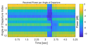
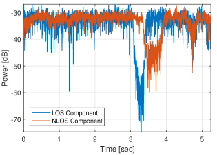
Fig. 4 demonstrates the results of two blockage measurements: (i) with a single person walking perpendicular to the LOS path and (ii) with three blockers following the paths as displayed in Fig. 3. The single blocker measurement has the arrays facing towards the wall so that the NLOS component is relatively strong. There are two distinct blockage events visible in the single blocker measurement – first the LOS component and then the NLOS component. There is an overlap between the two blockage events around the 3.5 second mark which has important implications for radio system design. If blockage mitigation is to be performed by switching between the LOS and NLOS path as each one experiences blockage, then an overlap similar to the one seen in Fig. 4 could mean that there is simply no way to steer around this particular blockage event.
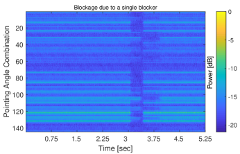
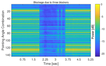
In the three-blocker measurement there is one very long blockage event on the LOS path due to the blocker who begins near the TX and walks toward the RX. This path is ‘unlucky’ due to the fact that the blocker spends a large amount of time blocking the LOS path but is certainly something that could occur in a real use case. There is also a NLOS path that survives for most of the duration of the LOS blockage with the exception of some brief blockage events that are much shorter than the LOS blockage event. We can see two brief instances between 3 and 3.75 seconds where the LOS component appears to be coming out of blockage, but then becomes blocked again. This was likely caused by small variations in the blocker’s path that briefly took him out of the way of the LOS between the TX and RX. These ‘false’ recoveries might incur additional overhead if a radio transceiver switches back to the LOS component because it senses that it has been restored – only to return to the blocked state shortly after. Overall, these measurements confirm that there is much to be gained from intelligent beam-tracking algorithms, which can select non-blocked paths.
Another way to visualize the results of our measurement is to plot the received power as a function of only the TX antenna weight vector (angle of departure) or the RX antenna weight vector (angle of arrival), while choosing the best pointing angle at the opposite end. An example of this plot for the single blocker measurement is introduced in Fig. 5. The latter is more intuitive than Fig. 4, which contains information from all of the possible combinations of the AoA and AoD.
By inspecting plots in the style of Fig. 5 or Fig. 4, it is possible to label blockage events on the LOS path and any clearly visible NLOS paths. In this study, we seek to understand the temporal correlation between LOS and NLOS blockage. By examining all of the measured data collected during this campaign for the single blocker and multi-blocker measurements, we were able to conclude that there was never a moment where the LOS path and both NLOS paths reflected off the left and right walls would be simultaneously blocked. This outcome bodes well for 60 GHz applications, but as mentioned earlier more measurements in other environments and with different blocker trajectories are certainly needed in order to draw authoritative conclusions. For example, this observation may not hold if Blocker 3 in Fig. 3 moved closer to the array. Further, this type of analysis is somewhat difficult to scale. As a way of automating the labeling process, we have developed a technique which uses a low-rank tensor decomposition to extract blockage profiles of the dominant paths in a single measurement.
IV-B Low-Rank Tensor Decomposition
A well-known method for reducing large datasets with multiple redundant or correlated entries is principal component analysis (PCA). PCA is suitable for a variety of problems and has been shown to be effective for interpreting the results of MIMO channel measurements at 6 GHz [14]. PCA can easily be applied by performing the singular value decomposition (SVD) of the data matrix; the SVD is available in most standard linear algebra software packages which makes PCA a very accessible form of analysis. Because the SVD is only defined for matrices and not tensors, there are two ways to conduct the intended analysis. One way is to perform another unfolding of the data tensor as discussed earlier, but this time also interleaving the pointing angle combination along with the delay dimensions. The resulting matrix can then be used for standard PCA. However, as shown in [11], this method is not as effective as other techniques, such as parallel factor analysis (PARAFAC), which generalize PCA to tensors. Intuitively, the PARAFAC model has fewer degrees of freedom than the equivalent PCA model which uses this interleaving process. If the PARAFAC model is sufficient to model the data, then these additional degrees of freedom can result in modeling noise or modeling system components in a redundant way [15]. The PARAFAC model expresses the data tensor as a sum of contributions from components, with each component defined as the outer product of its delay signature , its spatial signature , and its gain over time . In this way, PARAFAC provides a very elegant way of representing the results of a single measurement. The delay signature tells us how strongly correlated multipath component is with delay in the power delay profile and therefore at what delay this multipath component is arriving. The spatial signature tells us how strongly correlated the component is with pointing angle combination and can therefore be used to determine where in the environment this path was located. Lastly, the gain trajectory tells us how strong a particular component is at time . Because all variation in the gain of each path in this experiment should be due to blockage, we can use this to obtain a blockage trace for each path in the channel.
Fig. 6 displays the two gain trajectories and obtained from a PARAFAC model () that was produced for the single blocker measurement shown in Fig. 4. These two curves have a straightforward physical interpretation as the time-varying received power of the two multipath components visible in the measurement. This very simple and usable form can be directly employed for the construction of statistical models. For instance, by fitting a piecewise linear model to the two blockage trajectories and then assigning states of ‘Blocked’ or ‘Unblocked’ to each path in every time slot, the Markov model demonstrated in [13] can be developed jointly for multiple paths instead of one path.
V Conclusions and Future Work
Characterizing fast channel dynamics due to blockage is vital for virtually every aspect of mmWave radio system design. At the link layer, these models are needed for beam tracking, channel measurement and reporting, and link adaptation. At the upper layers, they impact cell selection, handover and congestion control. Models based on ray tracing, diffraction theory, or single directional measurements are difficult to generalize to more complex scenarios. In this work, we discussed the need for empirical studies of human-body blockage in mmWave communications. To address it, we developed and presented a novel methodology that can capture the spatial dynamics of mmWave channels using phased arrays. The system was demonstrated in a living room-type situation with multiple blockers.
The development of this tool can be regarded as a first step toward the ultimate goal, which is constructing an accurate statistical framework that captures the dynamic spatial and temporal nature of mmWave channels. Beyond the work presented here, we anticipate that two further steps will be needed. First, raw data collected from our system is enormous and some form of dimensionality reduction is required. We considered one possibility based on low-rank tensor decompositions, which can automatically extract the dominant paths and their trajectories. Second, we also need to fit a time-series type model to these trajectories. In this case, we have multiple gains from different directional paths. It is possible that the four-state models such as those used in IEEE 802.11 may apply, but these would have to be extended to handle the joint dynamics across multiple paths. This modeling challenge is an open and interesting one.
In addition to the statistical modeling of the existing data, our proposed methodology can also be applied to other scenarios of interest. For example, one can easily perform similar measurements in larger venues or public spaces, such as cafes and typical hotspots where 5G systems are likely to be deployed. The PARAFAC method in this work requires that the only change in the channel over time is due to blockage, but it is possible to explore other formulations of this method or pre-processing techniques which make it suitable for other types of channel dynamics.
References
- [1] M. Shafi et al., “5G: A tutorial overview of standards, trials, challenges, deployment, and practice,” IEEE Journal on Selected Areas in Communications, vol. 35, no. 6, pp. 1201–1221, June 2017.
- [2] M. Feng, S. Mao, and T. Jiang, “Dealing with link blockage in mmWave networks: D2D relaying or multi-beam reflection?” in 2017 IEEE 28th Annu. Int. Symp. on Personal, Indoor, and Mobile Radio Communi. (PIMRC), Oct 2017, pp. 1–5.
- [3] C. Gustafson and F. Tufvesson, “Characterization of 60 GHz shadowing by human bodies and simple phantoms,” in 2012 6th Eur. Conf. on Antennas and Propagation (EuCAP), April 2012, pp. 3084–3088.
- [4] M. Jacob et al., “A ray tracing based stochastic human blockage model for the IEEE 802.11ad 60 GHz channel model,” in 2011 5th Eur. Conf. on Antennas and Propagation (EuCAP), April 2011, pp. 473–477.
- [5] T. S. Rappaport et al., “Small-scale, local area, and transitional millimeter wave propagation for 5G communications,” IEEE Trans. on Antennas and Propagation, vol. 65, no. 12, pp. 6474–6490, Dec 2017.
- [6] M. Peter et al., “Analyzing human body shadowing at 60 GHz: Systematic wideband MIMO measurements and modeling approaches,” in 2012 6th Eur. Conf. on Antennas and Propagation (EuCAP), April 2012, pp. 468–472.
- [7] 3GPP, “Study on channel model for frequencies from 0.5 to 100 GHz (Release 14),” Jan. 2018, version 14.3.0 (Accessed Aug. 24 2018). [Online]. Available: https://portal.3gpp.org/desktopmodules/Specifications/SpecificationDetails.aspx?specificationId=3173
- [8] METIS, “METIS Channel Models,” Jul. 2015, Deliverable D1.4 v3 (Accessed Aug. 24 2018). [Online]. Available: https://www.metis2020.com/wp-content/uploads/METIS_D1.4_v3.pdf
- [9] Y. Wang et al., “Blockage and coverage analysis with mmwave cross street BSs near urban intersections,” in 2017 IEEE Int. Conf. on Commun. (ICC), May 2017, pp. 1–6.
- [10] S. Collonge, G. Zaharia, and G. E. Zein, “Influence of the human activity on wide-band characteristics of the 60 GHz indoor radio channel,” IEEE Trans. on Wireless Commun., vol. 3, no. 6, pp. 2396–2406, Nov 2004.
- [11] C. Slezak, A. Dhananjay, and S. Rangan, “60 GHz blockage study using phased arrays,” in 2017 51st Asilomar Conf. on Signals, Syst., and Comput., Oct 2017, pp. 1655–1659.
- [12] S. K. Saha et al., “X60: A programmable testbed for wideband 60 GHz WLANs with phased arrays,” in Proc. Workshop on Wireless Network Testbeds, Experimental Evaluation & CHaracterization, Oct 2017, pp. 75–82.
- [13] G. R. MacCartney, T. S. Rappaport, and S. Rangan, “Rapid fading due to human blockage in pedestrian crowds at 5G millimeter-wave frequencies,” in 2017 IEEE Global Commun. Conf., Dec 2017, pp. 1–7.
- [14] X. Ma et al., “A PCA-based modeling method for wireless MIMO channel,” in 2017 IEEE Conf. on Comp. Commun. Workshops (INFOCOM WKSHPS), May 2017, pp. 874–879.
- [15] R. Bro, “PARAFAC. tutorial and applications,” Chemometrics and Intelligent Laboratory Systems, vol. 38, no. 2, pp. 149 – 171, 1997.
| Christopher Slezak [GM] (chris.slezak@nyu.edu) received the B.S degree in Electrical and Computer Enginerring from Rutgers, the State University of New Jersey in 2014. He is currently a researcher at NYU WIRELESS working toward the Ph.D. degree at the NYU Tandon School of Engineering in Brooklyn NY. His research interests include wireless communications, millimeter wave channel measurements, and modeling of millimeter wave channel dynamics. |
| Vasilii Semkin (vasilii.semkin@tut.fi) is a Postdoctoral Researcher in the Laboratory of Electronics and Communications Engineering at Tampere University of Technology, Finland. He received B.Sc. degree from Saint-Petersburg State University of Aerospace Instrumentation, Russia, in 2009 and M.Sc. degree in 2011. He received Lic. Sc. (Tech.) in 2014 and D.Sc. (Tech.) in 2016 from Aalto University, School of Electrical Engineering. His interests comprise millimeter-wave communications, especially in the field of reconfigurable antennas and radio-wave propagation modeling. |
| Sergey Andreev [SM] (sergey.andreev@tut.fi) is a Senior Research Scientist in the Laboratory of Electronics and Communications Engineering at Tampere University of Technology, Finland. He received the Specialist degree (2006) and the Cand.Sc. degree (2009) both from St. Petersburg State University of Aerospace Instrumentation, St. Petersburg, Russia, and the Ph.D. degree (2012) from Tampere University of Technology. Sergey (co-)authored more than 150 published research works on wireless communications, energy efficiency, HetNets, cooperative communications, and M2M applications. |
| Yevgeni Koucheryavy [SM] (yk@cs.tut.fi) is a Full Professor in the Laboratory of Electronics and Communications Engineering of Tampere University of Technology (TUT), Finland. He received his Ph.D. degree (2004) from TUT. He is the author of numerous publications in the field of communications. His current research interests include heterogeneous wireless communication networks and systems, the IoT, and nanocommunications. He is Associate Technical Editor of IEEE Communications Magazine and Editor of IEEE Communications Surveys and Tutorials. |
| Sundeep Rangan [F] (sundeep.rangan@nyu.edu) is a Professor in Electrical and Computer Engineering at New York University and Director of NYU Wireless. He received his Ph.D. from the University of California, Berkeley. He co-founded (with four others) Flarion Technologies, that developed Flash-OFDM, the first cellular OFDM data system and pre-cursor to 4G LTE. Flarion was acquired by Qualcomm where Dr. Rangan was a Director of Engineering at Qualcomm before joining NYU. |