Bilateral Control of Two Finger Joints
Using Functional Electrical Stimulation
Abstract
Bilateral control, a remote-control technique, is used to work at a distance. However, many existing bilateral control systems have two common problems: 1) it is difficult to create a system like a human hand, that has multiple degrees of freedom and 2) if the mechanism becomes too complicated, operators feel restrained and experience discomfort. Because, for these reasons, the bilateral control of fingers has not been accomplished to date, we aimed to overcome this by applying functional electrical stimulation (FES). In our experiments, through an adhesive electrode pad, electrical stimulation was delivered to the muscles that flex and expand the metacarpophalangeal joints of the thumb and middle finger. Position-symmetrical bilateral control was implemented so that the deviation of the master’s and slave’s positions relative to each other was zero degrees. A sliding mode controller was used as a position controller. We found it possible to control multiple degrees of freedom; however, we found areas where the number of tracking errors was large. We speculated that the middle finger did not bend, because the arm rotates as the thumb was abduction, therefore the position of the motor point of the middle finger deviates from the position of the pad.
I Introduction
Robotic remote-control technology is useful in many situations, such as extreme environments and the medical field [1] [2].
Bilateral control, a type of remote-control technique, can transmit force information between a master and a slave. The force information received in the slave environment can be conveyed to the master [3] [4]. The operator can experience the actual feeling of the remote environment via bilateral controllers. Conventionally, bilateral control has been researched for use in the medical field and on disaster sites [5] [6].
However, many existing bilateral control systems have two common problems: 1) it is difficult to create a system with multi-degrees of freedom, like the human hand, and 2) as the mechanism becomes complicated, operators feel uncomfortable restrained. In the current paper, we aimed to solve these problems using functional electrical stimulation (FES) because it has already been demonstrated to achieve bilateral control [7] [8]; it has been used to restore function, by providing electrical stimulation, to permanently paralyzed limbs resulting from upper motor-neuron disorders such as spinal cord injury and stroke. Research into controlling the human body using FES has been actively conducted since the 1960s [9]. In recent years, the use of FES not only for rehabilitation but also to move the body has attracted much attention.
The following research has been carried on the use of FES for bodily control. Gollee et al. reproduced standing motions with an intact and a paraplegic subject using linear second Gaussian control of FES [10]. Ching et al. proposed using neural network (NN) in combination with PID control to improve control performance [11]. Ajoudani et al. proposed control by combining NN and sliding-mode control [12]. Tamaki et al. controlled hands using FES; they showed that it was possible to use hands to help play a musical instrument [13]; they used FES to move their fingers and tried to reproduce the object’s gripping motion by performing closed-loop control using a force sensor [14]. Kitamura et al. performed bilateral control of an elbow joint using FES [15]. These various studies indicate that FES is useful for control. However, the bilateral control of fingers has not yet been reported in any studies to the best of our knowledge. Human fingers are capable of many varied motions; if FES is to be used as a remote-control technology in the future, it is imperative that it can bilaterally control the movement of fingers. Therefore, in this paper, as initial research into the bilateral control of fingers using FES, bilateral control of a movement of the thumb and middle finger was performed by applying electrical stimulation. Moreover, Farhoud et al. confirmed that control is improved by using a high-order sliding mode control for an operation using FES [16]. Therefore, in this paper, bilateral control using FES was also performed using high-order sliding mode control.
The current paper is organized as follows; Section II describes FES; Section III describes bilateral control, Section IV describes sliding mode control, Section V describes the experimental environment, Section VI describes the experimental method, Section VII describes and discusses the experimental result of the bilateral control, and Section VIII concludes this paper.
II Functional Electrical Stimulation
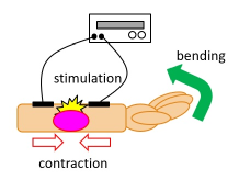
In this section, FES is described and is conceptually illustrated in Fig. 1. FES delivers electrical stimulation to peripheral nerves using an external power source and excites the peripheral nerves; in this way, it is possible to drive the body.
II-A Stimulation Method
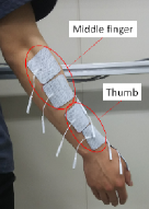
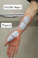
In this experiment, electrostimulation was delivered to the forearm using an adhesive pad for safety and convenience consideration. To drive the thumb and middle finger, we stimulated the flexor and extensor apollicis brevis muscles, the pollicis brevis muscle, the flexor digitorum superficialis muscle, and the extensor digitorum muscle. The flexor works in the direction that bends the fingers and the extensor works in the direction that extends the fingers. Fig. 2 shows the locations of the pads.
 [A]Extensor muscle
 [B]Flexor muscle
|
II-B Stimulation Waveform
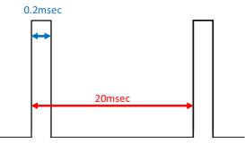
In this experiment, we used a pulse wave because it is convenient and commonly used. Fig. 3 shows the stimulation waveform with a frequency of 50 Hz and a pulse width of 0.2 msec. The frequency was selected from 20, 50 and 100 Hz the value at which the muscle reacted the most.
III Bilateral Control
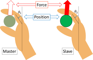
In this section, bilateral control, a remote-control technique [17] [18], is described and is illustrated in Fig. 4. The operator side is called a master and the operated side is called a slave. The slave follows the movement of the master. In addition, forces applied to the slave are feed back to the master. Therefore, the master feels as if it is in the slave’s location [19] [20]. There are several types of bilateral control; however, in this paper, we used position-symmetrical bilateral control because the control system for this method is simple and stable and does not require a force sensor.
IV Sliding Mode Control
In this section, sliding mode control is described. The objective of the sliding mode controller is that the system state vector converges to the desired state vector depending on the effect of uncertainty such as disturbance or modeling error [21]. A general sliding mode control satisfies the control goal when the sliding manifold is on the sliding manifold (ie, when ). The sliding manifold is defined as follows:
| (1) | |||||
| (2) |
where, is a positive constant. Also, represents the deflection between the target value and the measured value of the finger joint angle, represents the target value of the angle, and represents the measured value of the angle. In the current paper, because angle and angular velocity are inputted, the order n of the input variable is . However, for this classical sliding mode control, the problem of oscillatory, high-frequency input, called chattering, arises; therefore, high order sliding mode (HOSM) control was used. HOSM control works on higher-order derivatives compared to standard sliding variables. The control target of the HOSM controller can be described by Eq. (3) using the sliding manifold s given in Eq (1).
| (3) |
In the HOSM controller, the high-order element s, which increases when chattering occurs, consequently converges to zero, and therefore, chattering can be suppressed.
In the current paper, we used a super-twisting algorithm to realize HOSM control [21]. This algorithm was developed to avoid the chattering phenomena. The high-order element s contains up to second order terms that do not depend on the derivative of the sliding variable. In this paper, the control input , satisfying the control target of , is defined as follows:
| (4) |
where, and are positive constants and is preferably 0.5 when [22]. It is difficult to identify the values of and . Therefore, it was determined that and by trial and error. After the values of these parameters were applied to both subjects, the experiments were carried out.
V Experiment Environment
In this section, the experiment environment is described.
V-A Electrical Stimulation Device
Table I shows the input and output of electrical stimulation device. We used a maximum output current less than the effective value of 20 mA in accordance with the Japanese Industrial Standard (JIS) for low-frequency therapy devices. In addition, in consideration of the subject’s safety and to reduce their discomfort, we restricted the stimulation voltage to a 30 V maximum.
| Supply voltage | 50 V |
|---|---|
| Output voltage(Effective value) | 45 V |
| Output current(Effective value) | 20 mA |
V-B Angle Measuring Device
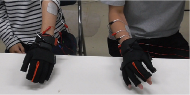
We measured the angle of the finger joint using a data glove (Manus VR, Eindhoven. Netherlands) (Fig. 5). The joint angle of each finger was measured by flexible sensors in the glove’s fingers.
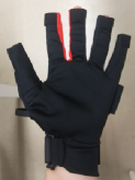 [A]The palm side
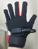 [B]The back side
|
VI Methods
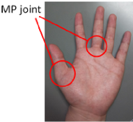
In this section, the experimental method is described. The subjects, referenced as A and B, were two healthy men aged in their twenties. We explained the content and objectives of the experiment to the subjects and conducted the experiments after obtaining their informed consent. Permission from the ethics committee of the Saitama University was obtained for this experiment. For the experiment, we used the metacarpophalangeal (MP) joints of the thumb and middle finger, shown in Fig. 6, for bilateral control. The joint angle when the fingers were extended was set to 0 deg and when the fingers were flexed was set to 90 deg. Fig. 7 shows the experimental setup.
VI-A Determination of Electrical Stimulation Position
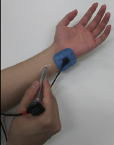
For the experiment, we selected a muscle to drive the MP joints of the thumb and middle finger using a motor point pen (MPP) (COMPEX). By using an MPP, it was possible to find the part where the muscles tended to respond to electrical stimulation (motor point) (Fig. 8).
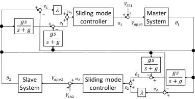
VI-B Control System
The control system used in this experiment is shown in Fig. 9. The inputs, and , to the sliding mode controller can be expressed by the following equations derived from Eqs (1), (2);
| (5) | |||
| (6) |
where the output is the stimulation voltage; when is positive, the muscles which bend the finger joints are stimulated, and when is negative, the muscles which extend the finger joints are stimulated. However, human muscles do not contract unless a voltage exceeding a threshold voltage is applied. Therefore, in this experiment, the threshold voltage was selected for each subject, and the stimulation voltage amplitude can be expressed as follows:
| (7) |
The angular velocity was obtained by pseudo-differentiating the angle, and the cutoff frequency was set at 6.28 Hz.
VII Experimental Results and Discussion
In this section, we describe the results of the experiment.
First, two subjects were selected, and one subject became a master and the other subject became a slave. A short instruction gPlease freely move the finger joint h was given to the master. Simultaneously, a short instruction gPlease do not look at the hand of the master h was given to the slave. The duration of the experiment was 25 s. After this, the master and slave swapped places, and the same 25 s experiment was repeated.
We conducted three kinds of experiments using FES as follows:
-
•
bilateral control of the thumb
-
•
bilateral control of the middle finger
-
•
bilateral control of both the thumb and the middle finger
The experimental results are given below.
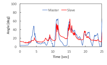
VII-A Bilateral Control of Thumb Using FES
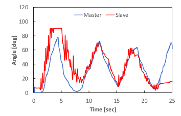
The results of the experiment using subject A as the master and subject B as the slave are shown in Fig. 10. Those with subject A as the slave and subject B as the master are shown in Fig. 11. From these result, we confirmed that the thumb of the slave followed the thumb of the master.
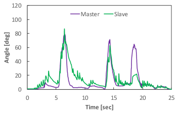
VII-B Bilateral Control of Middle Finger Using FES
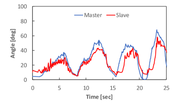
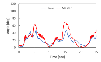
The results of the experiment with subject A as the master and subject B as the slave are shown in Fig. 12. Those with subject A as the slave and subject B as the master are shown in Fig. 13. From these results, it was shown that the movement of the middle finger of the slave generally followed the movement of the middle finger of the master. However, it was evident that there was a period when errors increased.
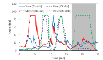
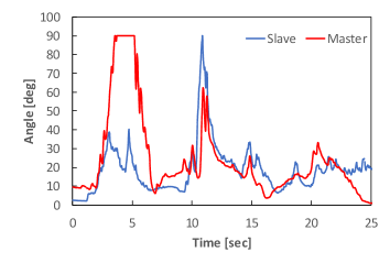
VII-C Bilateral Control of Thumb and Middle fingers using FES
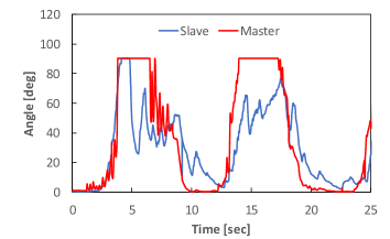
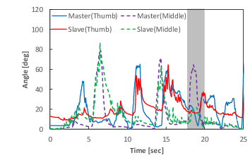
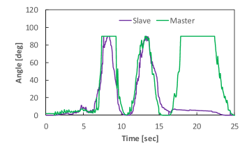
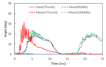
The results of the experiments with subject A as the master and subject B as the slave are shown in Fig. 14. Those with subject A as the slave and subject B as the master are shown in Fig. 15. In addition, Figs. 16-19 focus on the motions of the thumb and the middle finger shown in Figs. 14 and 15. Figs. 14-19 are free motion data. In addition, contact motion with subject A as the master and subject B as the slave grabbing a cylinder with a diameter of 5 cm is shown in Fig. 20. Figs. 14-20 also confirmed where the slave followed the motion of the master. However, compared to when the thumb and middle finger were individually, bilaterally controlled, many motions were not followed exactly.
From the gray part of Figs. 14 and 15, error of the middle finger was increased, when middle fingers were bent for the third time. We speculated that the middle finger did not bend, because the arm rotated as the thumb was abduction, therefore the position of the motor point of the middle finger deviated from the position of the pad. In order to solve this problem, we need to investigate the movement of the muscles of the forearm when electric stimulation is delivered, and to devise a mechanism that the stimulation position does not deviate from the motor point. In addition, we speculated that the thumb’s time constant became large, because since the setting of the control gain of the thumb could not be set well in Fig. 20.
VIII Conclusion
We proposed the bilateral control of two degrees of freedom in a thumb and a middle finger using FES. In an experiment, we recorded the motion of the thumbs and the middle fingers of two subjects during bilateral control and confirmed that the slave followed the motion of the master. However, we found a period of time where the tracking error was large. We speculated that the middle finger did not bend, because the arm rotated as the thumb was abduction, therefore the position of the motor point of the middle finger deviated from the position of the pad. We will devise a mechanism that the stimulation position does not deviate from the motor point and aim to further increase the degree of freedom.
Acknowledgement
This work was entrusted by the KDDI Foundation and JST, PRESTO Grant Number JPMJPR1755, Japan.
References
- [1] C. C. Abbou, A. Hoznek, L. Salomon, L. E. Olsson, A. Lobontiu, F. Saint, A. Cicco, P. Antiphon, and D. Chopin: “Laparoscopic radical prostatectomy with a remote controlled robot,” The Journal of urology, vol. 165, no. 6, pp, 1964-1966, 2001.
- [2] G. Hirzinger, B. Brunner, J. Dietrich, and J. Heindl: “ROTEX-the first remotely controlled robot in space,” Robotics and Automation, pp, 2604-2611, 1994.
- [3] D. Takahashi, T. Furuya, S. Sakaino, T. Tsuji, and Y. Kaneko: “Experimental evaluation of bilateral control of velocity control system using electric and hydraulic actuators,” Industrial Electronics Society, IECON 2013-39th Annual Conference of the IEEE, pp, 4120-4125, 2013.
- [4] S. Sakaino, T. Sato, and K. Ohnishi: “Multi-DOF micro-macro bilateral controller using oblique coordinate control,” IEEE Transactions on Industrial Informatics, vol. 7, no. 3, pp, 446-454, 2011.
- [5] S. Katsura, W. Iida, and K. Ohnishi: “Medical mechatronics-An application to haptic forceps,” Annual Reviews in Control, vol. 29, no. 2, pp, 237-245, 2005.
- [6] H. Yamada, N. Tao, and Z. Dingxuan: “Construction tele-robot system with virtual reality,” Robotics, Automation and Mechatronics, 2008 IEEE Conference on, pp, 36-40, 2008.
- [7] T. Kitamura, S. Sakaino, and T. Tsuji: “Bilateral control using functional electrical stimulation,” Industrial Electronics Society, IECON 2015-41st Annual Conference of the IEEE, pp, 2336-2341, 2015.
- [8] H. Mizoguchi, T. Kitamura, S. Sakaino, and T. Tsuji: “Bilateral Control Using Functional Electrical Stimulation Considering Muscle Length,” The IEEJ International Workshop on Sensing, Actuation, Motion Control, and Optimization(SAMCON2016), TT8-6, 2016.
- [9] C. L. Lynch, and M. R. Popovic: “Closed-loop control for FES: Past work and future directions,” 10th Annual Conference of the International FES Society, pp, 2-4, 2005.
- [10] H. Gollee, K. J. Hunt, and D. E. Wood: “New results in feedback control of unsupported standing in paraplegia,” IEEE Transactions on Neural Systems and Rehabilitation Engineering, vol. 12, no. 1, pp, 73-80, 2004.
- [11] G. C. Chang, J. J. Lub, G. D. Liao, J. S. Lai, C. K. Cheng, B. L. Kuo, and T. S. Kuo: “A neuro-control system for the knee joint position control with quadriceps stimulation,” IEEE transactions on rehabilitation engineering, vol. 5, no. 1, pp, 2-11, 1997.
- [12] A. Ajoudani, and A. Erfanian: “A neuro-sliding-mode control with adaptive modeling of uncertainty for control of movement in paralyzed limbs using functional electrical stimulation ,” IEEE Transactions on Biomedical Engineering, vol. 56, no. 7, pp, 1771-1780, 2009.
- [13] E. Tamaki, T. Miyaki, and J. Rekimoto: “PossessedHand: techniques for controlling human hands using electrical muscles stimuli,” Proceedings of the SIGCHI Conference on Human Factors in Computing Systems, pp, 543-552, 2011.
- [14] C. Freschi, F. Vecchi, S. Micera, AM. Sabatini, and P. Dario: “Force control during grasp using FES techniques: preliminary results,” 5th Annual Conference of the International Functional Electrical Stimulation Society (IFESS 2000), pp, 17-24, 2014.
- [15] T. Kitamura, N. Mizukami, H. Mizoguchi, S. Sakaino, and T. Tsuji: “Bilateral Control in the Vertical Direction Using Functional Electrical Stimulation.”IEEJ Journal of Industry Applications. vol. 5, no. 5, pp, 398-404, 2016.
- [16] A. Farhoud, and A. Erfanian: “Fully Automatic Control of Paraplegic FES Pedaling Using Higher-Order Sliding Mode and Fuzzy Logic Control,” IEEE Transactions on Neural Systems and Rehabilitation Engineering, Vol. 22, No. 3, pp, 533-542, 2014.
- [17] I. Takeuchi, and S. Katsura: “Motion Reproduction with Time-adaptation control for Dealing with Variations of Environmental Location,” IEEJ Journal of Industry Applications, Vol. 5, No. 3, pp, 221-227, 2016.
- [18] S. Hyodo, and K. Ohnishi: “A Bilateral Control System to Synchronize with Haptic and Visual Sense for Teleoperation over Network,” IEEJ Journal of Industry Applications, Vol. 5, No. 5, pp, 370-377, 2016.
- [19] D. Yashiro, K. Yubai, and S. Komada: “Fast Estimation of Environment’s Stiffness for Bilateral Control Systems with Communication Delay,” IEEJ Journal of Industry Applications, Vol. 5, No. 6, pp, 422-428, 2016.
- [20] H. Murata, and S. Katsura: “Improvement of operationality under time varying delay for bilateral teleoperation systems by differential signal based data modulation,” IEEJ Journal of Industry Applications, Vol. 6, No. 3, pp, 245-251, 2017.
- [21] A. Farhoud, and A. Erfanian:“Higher-order sliding mode control of leg power in paraplegic FES-cycling.” Engineering in Medicine and Biology Society (EMBC), 2010 Annual International Conference of the IEEE, pp, 5891-5894, 2010.
- [22] T. Kitamura, H. Mizoguchi, N. Mizukami, S. Sakaino, and T. Tsuji: “Chattering reduction of functional electrical stimulation with the smith compensator.” Industrial Electronics Society, IECON 2017-43rd Annual Conference of the IEEE, pp, 7577-7582, 2017.
- [23] O. Camacho, C. Smith, and W. Moreno: “Development of an internal model sliding mode controller.”Industrial Engineering Chemistry Research, vol. 41, pp, 568-573, 2003.