Drastic Reduction of Plasmon Damping in Two-Dimensional Electron Disks
Abstract
The plasmon damping has been investigated using resonant microwave absorption of two-dimensional electrons in disks with different diameters. We have found an unexpected drastic reduction of the plasmon damping in the regime of strong retardation. This finding implies large delocalization of retarded plasmon field outside the plane of the two-dimensional electron system. A universal relation between the damping of plasmon polariton waves and retardation parameter is reported.
pacs:
73.23.-b, 73.63.Hs, 72.20.My, 73.50.MxStudies of plasma excitations in 2DESs have attracted an increasing interest in recent years Heitmann:86 ; Lusakowski:16 . This interest has been triggered by a discovery of an absolutely new part of 2D plasmon spectrum, where coupling with light is especially strong Kukushkin:03 ; Muravev:06 . This regime, where the influence of the retardation is important, can be realized when the plasmon and light wavelengths become comparable. The influence of the electrodynamic effects can be quantified by the retardation parameter , defined as the ratio of the frequency of the quasi-static 2D plasmon to the frequency of light in the medium with the same wave vector Stern:67
| (1) |
where and are the density and effective mass of the 2D electrons, respectively. Here, effective permittivity of the surrounding medium is the average dielectric constant of GaAs () and free space. These experiments revealed very interesting and fully unexpected features of the 2D magnetoplasmon spectra. It has been shown that in the small wave-vector and high-density regimes, where the influence of the retardation effects is prominent, there is a strong reduction of the resonant plasma frequency with very unusual zigzag behavior in field.
These experiments served as a benchmark for a plethora of research in the field of 2D plasma electrodynamics, such as the strong and ultrastrong coupling between 2D electrons and photonic cavity mode Gunter:09 ; Todorov:10 ; Muravev:11 ; Science:12 ; Zhang:16 , super-radiant Dicke decay of the 2D electron ensemble Zudov:14 ; Sirtori:15 ; Muravev:16 , and fine structure of the cyclotron resonance Muravev:16 . It is widely accepted that retardation is associated with a dramatic broadening of the plasmon polariton resonance Sonnichsen:02 ; Mikhailov:05 ; Andreev:14 . The main reason for that is a significant increase of radiative decay. This fact has conceptually hampered the progress of research in the direction of plasmonic systems placed in the regime of ultra strong retardation. The regime which is potentially very attractive for plasmonic applications Shaner ; Knap ; Popov .
In this Letter we systematically studied the plasmon damping in 2DES disks as a function of their diameter. The measurements reveal that, in contrast to general belief, there is a drastic suppression of plasmon damping in the regime of strong retardation. Our results allowed us to draw important conclusions about delocalization of retarded plasmon field outside the plane of 2DES. Moreover, we established a universal relation between the damping of plasmon polariton waves and retardation parameter. These results pave the way for research in the field of ultra strong light-matter interaction.
This study was performed using a set of high-quality GaAs/AlxGa1-xAs () heterostructures hosting a 2DES in a nm quantum well. The electron density was in the range of to cm-2, with an electron transport mobility in the range of to cm(V s). Disk-shaped mesas with diameters in the range of mm to mm were fabricated from these heterostructures. The plasma wave in the disk was excited by electromagnetic radiation guided to the sample either through the waveguide section or with a coaxial cable. The detailed description of the experimental scheme is given in the Supplemental Material I Supplemental . In the latter case, the radiation from the coaxial cable was transferred to the 2DES through a coplanar waveguide transmission line. In order to detect 2D electron plasma excitations, we employed a non-invasive optical technique of microwave absorption detection Ashkinadze ; Kukushkin:02 . This technique relies on the high sensitivity of the 2DES luminescence spectra to 2D-electrons heating caused by the absorption of incident microwave radiation. In this technique, 2DES luminescence spectra with and without microwave radiation were collected using a spectrometer with a liquid-nitrogen cooled charge-coupled device (CCD) camera. The resulting differential spectrum reveals microwave-caused 2DES temperature heating. Therefore, the integral of the absolute value of the differential spectrum could be used as a measure of the microwave absorption by the 2DES. In our experiments, we used a nm stabilized semiconductor laser with a net output power of mW to excite 2D luminescence, and single-grating spectrometer with a spectral resolution of meV to analyze the luminescence spectra. All of the experiments were performed in the liquid-helium with a superconducting magnet at a base temperature of K. The magnetic field was directed perpendicular to the sample surface and swept in the range of T.
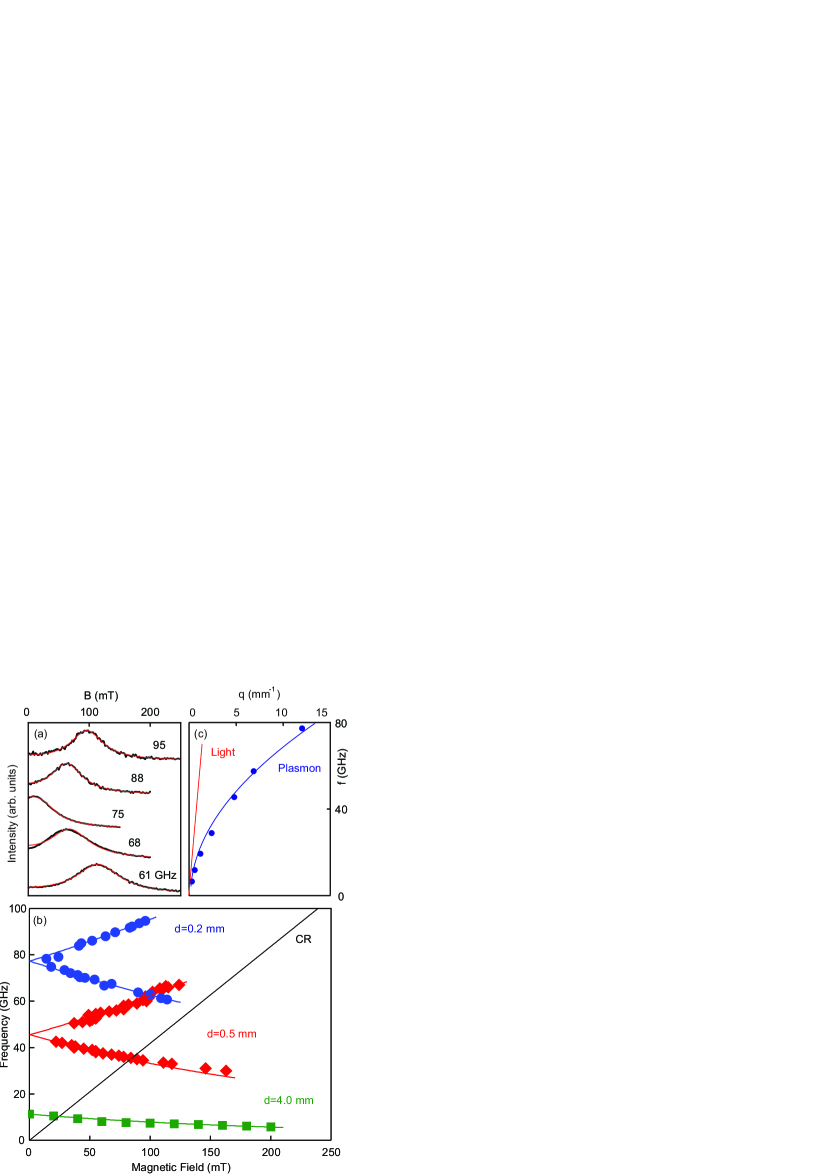
Figure 1(a) shows the experimental magnetic-field dependences of the microwave absorption at different frequencies in a 2DES disk with a diameter of mm and electron density of cm-2. For convenience, the curves are shifted vertically. Each of the curves shows resonance occurring at different magnetic-field values. The resonance corresponds to the excitation of the plasma oscillation in the disk. In order to obtain the resonance position and half-width, each magneto-absorption curve was fitted using a theory that considers both resonant heating and non-resonant Drude absorption (solid lines in Fig. 1(a)). The detailed fitting procedure is described in the Supplemental Material II Supplemental . Figure 1(b) shows the magnetic-field values at which plasmon resonances occur as a function of the the microwave frequency for the disks with diameters of , and mm. The theoretical prediction for the magneto-dispersion of plasma waves in the 2DES disks is Allen:83 ; Shikin :
| (2) |
where is the cyclotron frequency. In the presence of the retardation effects this dependency is modified Kukushkin:03 ; Mikhailov:05 ; Muravev:06 . Both zero-field plasmon frequency and slope of the magnetodispersion dependency decrease. By fitting the theoretical prediction to the data (solid curves in Fig. 1(b)), we can obtain the zero-field plasmon frequency. For the disk under consideration ( mm), the zero magnetic field plasmon frequency GHz. We assign to each plasmon mode a wave vector Kukushkin:03 . The experiments of Fig. 1(a) were performed for a serious of 2DES disks with diameters of , , , , , , , and mm. The resultant long-wavelength part of the plasmon polariton dispersion at T is plotted in Fig. 1(c). The solid curve represents the theoretical 2D plasmon polariton dispersion Kukushkin:03 . The dispersion of light is also shown in the same figure. The plasmon polariton dispersion strongly deviates from the quasi-static law, and asymptotically tends to the light line in the limit of a large retardation.
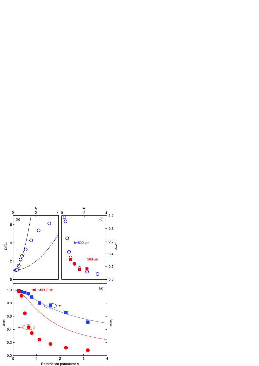
The red circles in Fig. 2(a) represent the dependence of the normalized plasmon polariton half-width on the retardation parameter . The retardation parameter is calculated using the definition of Eq. (1). The resonance half-width was determined by two mutually consistent methods. The first method directly utilizes frequency scans at T (see inset in Fig. 3). The second method uses magnetic-field scans at a fixed microwave frequency. The polariton half-width is then obtained from the half-width of the polariton resonance in sweeps multiplied by the magneto-dispersion slope . The was obtained by fitting the experimental absorption curves using the theory that considers both resonant heating and non-resonant Drude absorption (see Supplemental Material II Supplemental ). We verified that both methods yield the same value of for a series of studied disks.
Figure 2(a) also shows the normalized plasmon frequency as a function of (blue squares). It is remarkable that the plasmon half-width drastically decreases with . Moreover, the decreases significantly faster than the resonance frequency . These result implies that the retarded plasmon field is concentrated in a region , significantly larger than the region in which the dissipation occurs Falko:89 . Indeed, the plasmon polariton damping can be estimated by the formula (we present a precise theoretical derivation in Supplemental Material III Supplemental ):
| (3) |
The delocalization of the plasmon mode perpendicular to the 2DES plane is determined by . This relation is a direct consequence of the Maxwell’s equations for the bound electromagnetic wave propagating along the 2DES, . Considering the retardation effects, the plasmon polariton dispersion can be very simply expressed as Stern:67 :
| (4) |
By combining Eq. (3) and Eq. (4), we can derive the following expressions for the plasmon polariton frequency and damping:
| (5) |
In the limit of a not-large retardation, these equations can be expanded in series, leading to:
| (6) |
We denoted the non-retarded plasmon resonance Q-factor as . It should be noted that Eq. (3) is similar to suppression of the atomic spontaneous emission occurring in the resonator with a unitary Q-factor. This effect has been originally predicted by Purcell Purcell . The coincidence is not accidental, it stems from the unified nature of all electrodynamic phenomena.
Formula (5) predicts that decreases with faster than the frequency . This is consistent with our experimental results in Fig. 2(a). However, although the plasmon polariton frequency closely follows the theory (blue line in Fig. 2(a)), the resonance narrows with the increase of the retardation parameter significantly faster than the theoretical prediction (red line in Fig. 2(a)). In order to establish a direct comparison with our theory, we plot the normalized Q-factor, , as a function of the retardation parameter (Fig. 2(b)). The solid line in Fig. 2(b) represents a quadratic-function () fitting. The experimental data closely follow the quadratic dependence for a relatively small retardation (). This quantitatively agrees with Eq. (6), albeit the plasmon damping is suppressed relative to the theory (dashed line in Fig. 2(b)). One may assume that suppression of the plasmon polariton damping is associated with an effect of the semiconductor substrate. In order to test this possibility, we performed measurements (Fig. 2) on the same set of samples thinned from the original mm to mm. Figure 2(c) shows a comparison of the normalized plasmon half-widths measured for the samples with thicknesses of mm (open circles) and mm (filled squares). The main observation to note is that the substrate thickness does not affect the plasmon polariton damping. We can speculate that a more adequate theoretical consideration for the retardation in the studied 2DES geometry is certainly imperative. The discovered phenomenon is significant in terms of both physics and technology.
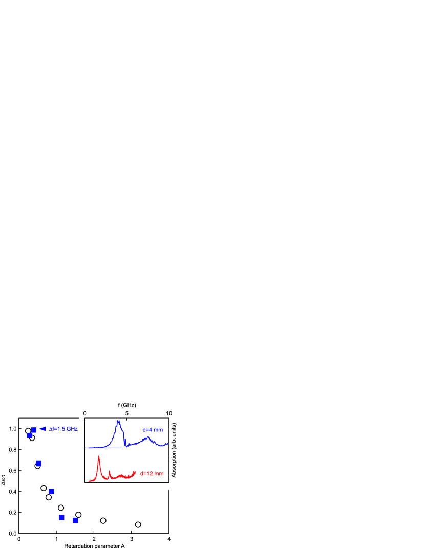
One of the most important predictions of the theory is that there is a universal relationship between the normalized plasmon damping and retardation parameter . In order to investigate this relation, we repeated the experiment of Fig. 2 for 2DES disks fabricated from three different wafers in terms of density and relaxation time . Figure 3 shows the normalized plasmon polariton half-width as a function of the retardation parameter . The measurements were performed for two wafers with electron densities and relaxations of cm-2 and s-1 (empty circles), and cm-2 and s-1 (blue squares), respectively. The plasmon normalized dampings for the samples fabricated from the two wafers indeed have an idendical dependence on the parameter . The same universal dependence was also reproduced for the third wafer with cm-2 and s-1 (see Supplemental Material IV Supplemental ). The discovered universality has a remarkably general nature and is applicable to any type of 2D plasmons.
In conclusion, we have investigated resonant microwave absorption in 2DES disks with diamaters in the range of mm to mm. The plasmon polariton mode excited in the disks has been detected by the optical technique. We have demonstrated an unexpected anomalous suppression of the plasmon damping when the retardation became important. Remarkably, the dependence of the normalized resonance half-width on the retardation parameter has a universal character and does not depend on the 2DES parameters and semiconductor substrate thickness.
We thank L.S. Levitov and V.A. Volkov for the stimulating discussions. The authors gratefully acknowledge the financial support from the Russian Science Foundation (Grant No. 14-12-00693).
References
- (1) D. Heitmann, Surf. Science 170, 332 (1986).
- (2) J. Łusakowski, Semicond. Sci. and Technol. 32, 013004 (2016).
- (3) I. V. Kukushkin, J. H. Smet, S. A. Mikhailov, D. V. Kulakovskii, K. von Klitzing, and W. Wegscheider, Phys. Rev. Lett. 90, 156801 (2003).
- (4) I. V. Kukushkin, V. M. Muravev, J. H. Smet, M. Hauser, W. Dietsche, and K. von Klitzing, Phys. Rev. B 73, 113310 (2006).
- (5) F. Stern, Phys. Rev. Lett. 18, 546 (1967).
- (6) G. Günter, A. A. Anappara, J. Hees, A. Sell, G. Biasiol, L. Sorba, S. De Liberato, C. Ciuti, A. Tredicucci, A. Leitenstorfer, and R. Huber, Nature (London) 458, 178 (2009).
- (7) Y. Todorov, A. M. Andrews, R. Colombelli, S. De Liberato, C. Ciuti, P. Klang, G. Strasser, and C. Sirtori, Phys. Rev. Lett. 105, 196402 (2010).
- (8) V. M. Muravev, I. V. Andreev, I. V. Kukushkin, S. Schmult, and W. Dietsche, Phys. Rev. B 83, 075309 (2011).
- (9) G. Scalari, C. Maissen, D. Turcinkova, D. Hagenmüller, S. De Liberato, C. Ciuti, C. Reichl, D. Schuh, W. Wegscheider, M. Beck, and J. Faist, Science 335, 1323 (2012).
- (10) Qi Zhang, M. Lou, X. Li, J. L. Reno, W. Pan, J. D. Watson, M. J. Manfra and J. Kono, Nature Physics 12, 1005 (2016).
- (11) Qi Zhang, T. Arikawa, E. Kato, J. L. Reno, W. Pan, J. D. Watson, M. J. Manfra, M. A. Zudov, M. Tokman, M. Erukhimova, A. Belyanin, and J. Kono, Phys. Rev. Lett. 113, 047601 (2014).
- (12) T. Laurent, Y. Todorov, A. Vasanelli, A. Delteil, C. Sirtori, I. Sagnes, and G. Beaudoin, Phys. Rev. Lett. 115, 187402 (2015).
- (13) V. M. Muravev, I. V. Andreev, S. I. Gubarev, V. N. Belyanin, and I. V. Kukushkin, Phys. Rev. B 93, 041110(R) (2016).
- (14) C. Sönnichsen, T. Franzl, T. Wilk, G. von Plessen, J. Feldmann, O. Wilson, and P. Mulvaney, Phys. Rev. Lett. 88, 077402-1 (2002).
- (15) S. A. Mikhailov and N. A. Savostianova, Phys. Rev. B 71, 035320 (2005).
- (16) I. V. Andreev, V. M. Muravev, V. N. Belyanin, and I. V. Kukushkin, Appl. Phys. Lett. 105, 202106 (2014).
- (17) E. A. Shaner, Mark Lee, M. C. Wanke, A. D. Grine, J. L. Reno, and S. J. Allen, Appl. Phys. Lett. 87, 193507 (2005).
- (18) W. Knap, M. Dyakonov, D. Coquillat, F. Teppe, N. Dyakonova, J. Łusakowski, K. Karpierz, M. Sakowicz, G. Valusis, D. Seliuta, I. Kasalynas, A. Fatimy, Y. M. Meziani, T. Otsuji, Journal of infrared millimeter and terahertz waves 30, 1319 (2009).
- (19) V. V. Popov, D. V. Fateev, T. Otsuji, Y. M. Meziani, D. Coquillat, W. Knap, Appl. Phys. Lett. 99, 243504 (2011).
- (20) B. M. Ashkinadze, E. Linder, E. Cohen, and Arza Ron, Phys. Stat. Sol. 164, 231 (1997).
- (21) I. V. Kukushkin, J. H. Smet, K. von Klitzing, W. Wegscheider, Nature (London) 415, 409 (2002).
- (22) See Supplemental Material at XXX, which includes the detailed information about analysis of the plasmon resonance line shape, theory of plasmon polariton spectrum and damping, and additional data on damping of plasmon polariton waves for the third wafer.
- (23) V. I. Fal ko and D. E. Khmel nitskii, Zh. Eksp. Teor. Fiz. 95, 1988 (1989) [Sov. Phys. JETP 68, 1150 1152 (1989)].
- (24) E. M. Purcell, Phys. Rev. 69, 681 (1946).
- (25) S. J. Allen, Jr., H. L. Störmer, J. C. M. Hwang, Phys. Rev. B. 28, 4875 (1983).
- (26) S. S. Nazin and V. B. Shikin, Fiz. Nizk. Temp. 15, 227 (1989) [Sov. J. Low Temp. Phys. 15, 127 (1989)].