Improving the Modularity of AUV Control Systems
using Behaviour Trees
Abstract
In this paper, we show how behaviour trees (BTs) can be used to design modular, versatile, and robust control architectures for mission-critical systems. In particular, we show this in the context of autonomous underwater vehicles (AUVs). Robustness, in terms of system safety, is important since manual recovery of AUVs is often extremely difficult. Further more, versatility is important to be able to execute many different kinds of missions. Finally, modularity is needed to achieve a combination of robustness and versatility, as the complexity of a versatile systems needs to be encapsulated in modules, in order to create a simple overall structure enabling robustness analysis. The proposed design is illustrated using a typical AUV mission.
Index Terms:
robotic planning, behaviour trees, artificial intelligence, autonomous underwater vehiclesI Introduction
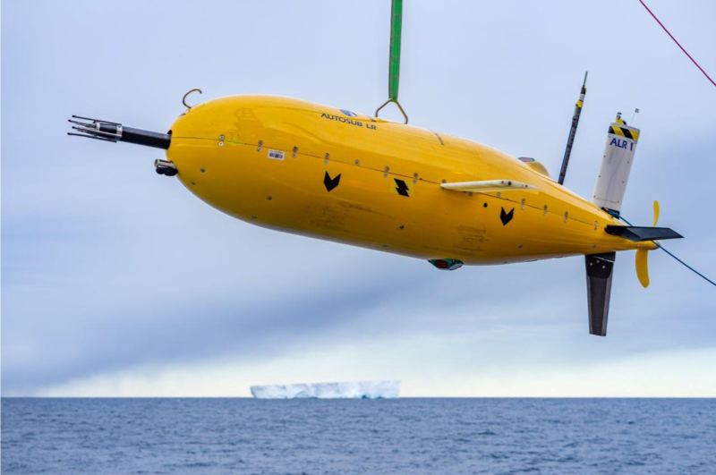
Due to the limitation in communication bandwidth and range, Autonomous Underwater Vehicles (AUVs), such as the one in Figure 1, cannot rely on tele-operation solutions in the same way that aerial and ground-based robots do [1]. Furthermore, the areas of operation of AUVs are often remote and hard to access by other means, making recovery of a malfunctioning AUV very difficult and costly [2]. For these reasons, the AUV control system needs to be both robust, to prevent the loss of vehicles, and versatile, to autonomously handle many different situations, see e.g., [3], on its own. These requirements lead to a trade-off in the complexity of the system, as robustness is often achieved by simplicity while versatility leads to complex systems. With this contribution we show how Behaviour Trees (BTs) can be used to design highly modular, versatile as well as robust, control architectures for AUVs.
BTs were invented in the computer game industry as a way to design complex, but modular, AI for in-game opponents [4, 5, 6]. Since then, they have been shown to generalise a significant set of popular robotic control architectures, including Finite State Machines, Decision Trees, the Subsumption Architecture and the Teleo-reactive approach [7, 8]. BTs have also been successfully used in the context of machine learning [9, 10, 11], training by demonstration [12], collaborative assembly robotics, [13] and surgical robotics [14].
II Background
It this section we give a brief description of BTs, but refer the interested reader to [15] for more details.
At the core, BTs are built from a small set of simple components, but just as many other powerful concepts, these components can be combined to create very rich structures.
Formally speaking, a BT is an acyclic directed graph (a tree) composed of nodes and edges. The nodes of the tree can be divided into six categories, Fallback, Sequence, Parallel, Action, Condition, Decorator, as listed in Table I.
With the standard meaning of child and parent in the tree context, the non-parent nodes are the interfaces to the physical AUV in terms of either Actions, where typically the AUV actuators are given commands, or Condition, where typically a condition is checked based on sensor data. All parent nodes of the tree are of the types Fallback, Sequence, Parallel, and Decorator, and are used to decide what Actions to execute, based on both Conditions and the outcomes of other Actions. A BT is executed by regularly sending Ticks to the root node. This is done with a user defined frequency, chosen depending on how fast the system should be able to react and how much computing power is available. When a node is ticked, it either forwards the tick to one of its children, as explained below, or does some type of computation, typically involving sensor data if it is a condition, or the transmission of commands to the actuators of the system if it is an action. We will now describe all node types in more detail.
The Sequence node executes Algorithm 1, which corresponds to routing the Ticks to its children from the left until it finds a child that returns either Failure or Running, then it returns Failure or Running accordingly to its own parent. It returns Success if and only if all its children return Success. Note that when a child returns Running or Failure, the Sequence node does not route the Ticks to the next child (if any). The Sequence node is drawn using the symbol \say, as shown in Figure 2.

The Fallback node111Fallback nodes are sometimes also called selector or priority selector nodes. executes Algorithm 2, which corresponds to routing the Ticks to its children from the left until it finds a child that returns either Success or Running. It then returns, accordingly, Success or Running to its own parent. It returns Failure if and only if all its children return Failure. Note that when a child returns Running or Success, the Fallback node does not route the Ticks to the next child (if any). The Fallback node is drawn using the symbol \say?, as shown in Figure 2.

The Parallel node executes Algorithm 3, which corresponds to ticking all of its children. The return status is then given by an aggregate of the return status of the children. Given a parameter , where is the number of children, it returns Success if at least children have succeeded, Failure if enough have failed to make the above impossible, and Running otherwise.
When an Action node receives Ticks, it executes a command, as in Algorithm 4. It returns Success if the action is successfully completed or Failure if the action has failed. While the action is ongoing it returns Running.
When a Condition node receives Ticks, it checks a condition, as in Algorithm 5. It returns Success or Failure depending on if the condition holds or not. Note that a Condition node never returns the status Running.
The Decorator node is a control flow node with a single child that manipulates the return status of its child according to a user-defined rule and also selectively Ticks the child according to some predefined rule. For example, a Max 10 sec decorator can start an internal timer the first time it is ticked, it then ticks its child and returns the corresponding return status for up to 10 seconds. After that it does not tick its child, but instead directly returns Failure, thus effectively limiting the execution time of its child to 10 seconds. Other examples of decorators are the invert decorator that always ticks its child, but swaps Success/Failure in the return status. For a more thorough description of BTs we refer the reader to the references given above.
| Node type | Symb. | Succeeds if | Fails if | Running if |
| Fallback | ? | one child succ. | all ch. fail | 1 ret. Running |
| Sequence | all ch. succ. | one ch. fails | 1 ret. Running | |
| Parallel | ch. succ. | ch. fail | else | |
| Action | text | Succeeded | Failed | else |
| Condition | text | If true | If false | Never |
| Decorator | Custom | Custom | Custom |
III Problem Formulation
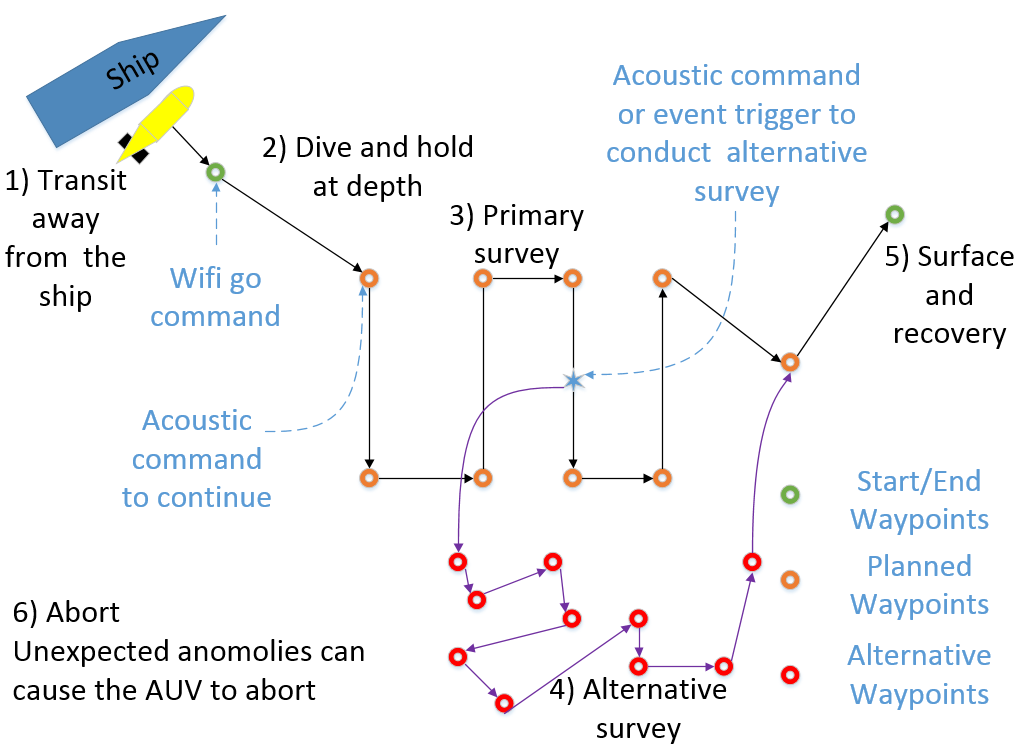
A typical AUV deployment is illustrated in Figure 4, and such missions are indicative of ship based deployments of AUVs [16]. The example assumes Wi-Fi and/or Iridum communication between the operator and the AUV while it is on the surface. Whilst submerged we assume low bandwidth acoustic communications enabling the operator to upload simple commands or new mission tasks (e.g., waypoints) and download basic diagnostic information. In this example the mission consists of six possible phases:
-
•
Transit away from the ship - initial phase where the AUV moves to a safe stand-off distance from the launch vessel and waits for an operator go command prior to diving.
-
•
Dive and hold at depth - the AUV dives, conducts in water calibration(s) (e.g. compass) and turns on payload(s) transits to a target depth and location while being monitored acoustically. The AUV waits for an acoustic command to continue.
-
•
Primary survey - the vehicle navigates between a series of waypoints sequentially, often resulting in a lawnmower pattern, while maintaining a constant water depth or altitude from the seabed.
-
•
Alternative survey - triggered either by an acoustic operator command or by a sensor reading the AUV may be tasked to undertake a secondary survey;
-
•
Surface and recovery - the final mission phase where the AUV returns to the surface, turns off payloads and is recovered from the water.
-
•
Abort in the event of unexpected anomalies (e.g. a detected leak) the vehicle will undertake an abort behaviour. In open ocean this involves dropping a weight while the AUV attempts to surface. When operating under ice more complex contingency behaviours are required. Such anomalous events include: over depth condition, under altitude condition, leak detected, propeller stuck detected, actuator stuck detected etc.
With the example mission structure in mind, we now consider what properties we want the AUV control system to exhibit. In general, the system should try to satisfy the following properties, or exhibit the corresponding behaviours, in the given order of priority. The AUV should:
-
1.
Maintain the safety of the AUV - the AUV should abort the mission in case of high risk anomalies (e.g. leaks, propeller stuck etc.) but also avoid obstacles appearing in its path and maintain a safe clearance from the seabed.
-
2.
Wait for operator clearance - specific phases of the mission should only start following a command from the operator. E.g. the primary survey should only start on receipt of a continue acoustic command from the operator indicating the system is fully prepared (e.g. payloads on and functioning correctly). This is particularly relevant for high risk operations e.g. under ice or in deep water where initial monitoring of the system is recommended to mitigate the risk of vehicle loss [17].
- 3.
-
4.
Finalise the Mission - return to the surface, turn payload(s) off and await recovery.
Considering the system’s properties, two sets of overall conditions and actions, as well as their pairings (behaviours), are generated, which will form the building blocks with which the eventual BT will be built. We will see that, although some conditions and actions are repeated among the set of behaviours, it will not result in redundant code, as a key practical benefit of using behaviour trees is their accommodation of reusing actions in several places in the tree.
IV Proposed Solution

Given the general mission properties outlined above, we create the general BT shown in Figure 5. As can be seen, the BT closely follows the list of desired properties of the system. First it checks is the system is safe, if not it performs a safety action. If safe, it goes on to check if a continue command has been issued, if not it executes the system preparations. If ordered to continue, it checks if the mission is synchronised with received updates and sensor data, if not it updates its mission. If synchronised, it checks if the mission is complete, if not it goes on to execute the mission. If the mission is complete it finalises the mission e.g., by turning off payloads and returning to the surface.
Note that all these checks are carried out with the frequency of the BT, making the system react immediately to a non safe situation, or new waypoints being received. This construction of combining a condition with the action needed to satisfy the condition is a simple version of the the postcondition-precondition-action (PPA) structure, described in [15].
Now we can refine the general BT given in Figure 5 to capture the details of the mission outlined in Figure 4. We want to add the following details to the BT:
-
1.
Safety: Abort mission in case of: inability to ascend/descend, actuator or propeller problems, leaks, too deep. Avoid obstacles on the way to the next waypoint.
-
2.
System preparation: keep away from ship, calibrate compass, payload on, go to target depth, wait for continue command.
-
3.
Mission synchronisation: go to surface if commanded, update waypoints if commanded acoustically by the operator or if updated by an on-board algorithm monitoring sensor data.
-
4.
Mission execution: go to next way point until all waypoints are visited.
-
5.
Mission finalisation: turn payload off and go to surface

The corresponding design can be seen in Figure 6. Note that the overall structure of Figure 5 has been maintained, with conditions being checked, and actions to satisfy those conditions being executed when needed, keeping the modular reactive design, while adding details to the execution. Thus, the robustness of a well tested safety behaviour is not jeopardised by adding complex details to the mission execution sub-tree. One could thus keep expanding upon the BT to an arbitrary level of detail.
V Example Executions
To illustrate the functionality of the proposed BT, we describe some sample mission executions. Suppose the AUV is submerged in proximity to the ship, as would be expected in the nominal mission scenario; this would yield the following condition checks and action executions: (but note that each number in the list below can correspond to one or arbitrarily many ticks, depending on how long the operation takes)
-
1.
Mission not aborted, able to ascend/descend, actuator and prop are operational, there aren’t any leaks, and not over depth, so don’t drop weight and go to surface (note that this condition is continuously checked).
-
2.
Not away from ship, so transit away from ship.
-
3.
Now away from ship, wait for go command.
-
4.
Go command received, so stop waiting!
-
5.
Is the compass calibrated? No, so calibrate it!
-
6.
Compass is now calibrated, check if the payload is powered on.
-
7.
Payload is now powered on, check if at target depth.
-
8.
Not at target depth, so go to target depth.
-
9.
Now at target depth, wait for the continue commands.
-
10.
Received continue command, so stop waiting!
-
11.
No commands to surface, so don’t surface.
-
12.
No user commanded waypoints, so don’t update waypoints.
-
13.
No waypoints received from autonomy, so don’t update way points.
-
14.
All waypoints not visited, so check position.
-
15.
Not at target waypoint, so go to target way point.
-
16.
Now at target waypoint, so assign new target as next way point.
-
17.
Not at the new target waypoint, so go to it.
-
18.
New waypoints received from either the operator or on-board autonomy, so updated waypoints.
-
19.
Keep following new waypoints.
-
20.
Eventually at terminal waypoint (mission complete), check if at surface.
-
21.
Not at surface, so go to surface.
-
22.
Now at surface, so check if payload is off.
-
23.
Payload is not off, so shut it down.
-
24.
Mission is now finalised.
Now consider a scenario in which a critical condition is encountered during the course of the mission execution:
-
1.
Mission not aborted, able to ascend/descend, actuator and prop are operational, there aren’t any leaks, and not over depth, so don’t drop weight and go to surface.
-
2.
…
-
15.
Not at target waypoint, so go to target way point.
-
16.
Still able to ascend/descend, actuator and prop are operational, but there is a leak! Set Mission Abort to TRUE. Drop weight and go to surface.
-
17.
Leak might stop due to reduced pressure, but Mission abort is still TRUE, so continue to surface.
-
18.
Stay at surface until picked up.
As can be seen above, the proposed controller results in a reactive and fault-tolerant mission execution. Furthermore, the resulting AUV mission specific BT retains the high level functionality described by the general mission critical system BT in Figure 5.
VI Conclusion and discussion
In this paper we have demonstrated that the BT framework is an advantageous approach for controlling mission critical systems. We have shown the sequence of steps one can take in order to transcribe the given system and mission requirements in a succinct, modular, and convenient manner, proceeding from a general design as shown in Figure 5 to a specific design in Figure 6.
With respect to safety, we have demonstrated that we are able to invoke safety checks with high precedence using node priority. We are able to ensure that at every moment in time the BT monitors the system’s safety before proceeding to other subsequent tasks.
With respect to modularity, we have demonstrated that, although there may be several behaviours that share mutual conditions and/or actions, single nodes can be implemented in a decentralised manner among several behaviours, eliminating the need for unnecessary code replication. Furthermore, because of this modularity, it is easy to see that behaviour trees can be described at varying levels of detail, as we have done in this paper whilst transitioning from the general BT in Figure 5 to the specific one in Figure 6. Finally, subtrees can be inserted or removed without changing the overall structure of the tree.
With respect to versatility, we have demonstrated that several different sub tasks can be accomplished in order of priority by being encapsulated into a single BT. This encapsulation delegates between tasks, and ensures that the control system can flexibly handle switching between the variety of tasks needed to be subsequently satisfied.
Lastly, with respect to robustness, we have demonstrated that, by using the PPA behaviour structure [15], as we do throughout this paper, we can always ensure that controls are being chosen with priority of goal fulfilment in mind. In the case of the BT in Figure 6, at the overall level behaviours are being executed to ultimately achieve mission finalisation, which requires the successful completion of all previous nodes in the main sequence.
Acknowledgment
This work was supported by Stiftelsen for StrategiskForskning (SSF) through the Swedish Maritime Robotics Centre (SMaRC) (IRC15-0046).
References
- [1] T. Fong and C. Thorpe, “Vehicle teleoperation interfaces,” Autonomous robots, vol. 11, no. 1, pp. 9–18, 2001.
- [2] S. D. McPhail, M. E. Furlong, M. Pebody, J. R. Perrett, P. Stevenson, A. Webb, and D. White, “Exploring beneath the PIG Ice Shelf with the Autosub3 AUV,” in OCEANS 2009-EUROPE (OCEANS), Apr. 2009, pp. 1–8.
- [3] Ö. Özkahraman and P. Ögren, “3d pursuit-evasion for AUVs,” arXiv preprint arXiv:1809.09876, 2018.
- [4] M. Mateas and A. Stern, “A Behavior Language for Story-based Believable Agents,” IEEE Intelligent Systems, vol. 17, no. 4, pp. 39–47, Jul. 2002.
- [5] D. Isla, “Handling Complexity in the Halo 2 AI,” in Game Developers Conference, 2005.
- [6] A. Champandard, “Understanding Behavior Trees,” AIGameDev. com, vol. Volume 6, 2007.
- [7] M. Colledanchise and P. Ögren, “How Behavior Trees Generalize the Teleo-Reactive Paradigm and And-Or-Trees,” in IEEE International Conference on Intelligent Robots and Systems (IROS), 2016, pp. 424–429.
- [8] M. Colledanchise and P. Ogren, “How behavior trees modularize hybrid control systems and generalize sequential behavior compositions, the subsumption architecture, and decision trees,” IEEE Transactions on robotics, vol. 33, no. 2, pp. 372–389, 2017.
- [9] M. Nicolau, D. Perez-Liebana, M. O’Neill, and A. Brabazon, “Evolutionary Behavior Tree Approaches for Navigating Platform Games,” IEEE Transactions on Computational Intelligence and AI in Games, vol. PP, no. 99, pp. 1–1, 2016.
- [10] M. Colledanchise, R. N. Parasuraman, and P. Ogren, “Learning of behavior trees for autonomous agents,” IEEE Transactions on Games, 2018.
- [11] C. I. Sprague and P. Ögren, “Adding neural network controllers to behavior trees without destroying performance guarantees,” arXiv preprint arXiv:1809.10283, 2018.
- [12] I. Sagredo-Olivenza, P. P. Gomez-Martin, M. A. Gomez-Martin, and P. A. Gonzalez-Calero, “Trained Behavior Trees: Programming by Demonstration to Support AI Game Designers,” IEEE Transactions on Games, vol. PP, no. 99, pp. 1–1, 2017.
- [13] C. Paxton, A. Hundt, F. Jonathan, K. Guerin, and G. D. Hager, “CoSTAR: Instructing Collaborative Robots with Behavior Trees and Vision,” in Robotics and Automation (ICRA), 2017 IEEE International Conference on, 2017, pp. 564–571.
- [14] D. Hu, Y. Gong, B. Hannaford, and E. J. Seibel, “Semi-autonomous Simulated Brain Tumor Ablation with Raven II Surgical Robot using Behavior Tree,” in IEEE International Conference on Robotics and Automation (ICRA), 2015.
- [15] M. Colledanchise and P. Ögren, Behavior Trees in Robotics and Al: An Introduction. CRC Press, 2018.
- [16] G. Salavisidis, A. Munafo, C. Harris, T. Prmapart, R. Templeton, M. Smart, D. Roper, M. Pebody, S. McPhail, and P. A. Rogers, E. and, “Terrain-aided navigation for long-endurance and deep-rated autonomous underwater vehicles,” Journal of Field Robotics, pp. 1–28, 2018.
- [17] M. P. Brito, G. Griffiths, and P. Challenor, “Risk analysis for autonomous underwater vehicle operations in extreme environments,” Risk Analysis: An International Journal, vol. 30, no. 12, pp. 1771–1788, 2010.
- [18] G. Ferri, A. Munafo, and K. D. LePage, “An Autonomous Underwater Vehicle Data-Driven Control Strategy for Target Tracking,” IEEE Journal of Oceanic Engineering, pp. 1–21, Feb. 2018.
- [19] A. Munafo, G. Ferri, K. LePage, and R. Goldhahn, “AUV active perception: Exploiting the water column,” in OCEANS 2017 - Aberdeen. IEEE, 2017, pp. 1–8.
- [20] A. Caiti, V. Calabrò, A. Munafo, G. Dini, and A. Lo Duca, “Mobile Underwater Sensor Networks for Protection and Security: Field Experience at the UAN11 Experiment,” Journal of Field Robotics, vol. 30, no. 2, pp. 237–253, Jan. 2013.
- [21] M. Colledanchise, D. Almeida, and P. Ögren, “Towards blended reactive planning and acting using behavior trees,” arXiv preprint arXiv:1611.00230, 2016.