Formally Verified Hardware/Software Co-Design for Remote Attestation
Abstract
Remote Attestation () is a distinct security service that allows a trusted verifier () to measure the software state of an untrusted remote prover (). If correctly implemented, allows to remotely detect if is in an illegal or compromised state. Although several approaches have been explored (including hardware-based, software-based, and hybrid) and many concrete methods have been proposed, comparatively little attention has been devoted to formal verification. In particular, thus far, no designs and no implementations have been formally verified with respect to claimed security properties.
In this work, we take the first step towards formal verification of by designing and verifying an architecture called VRASED: Verifiable Remote Attestation for Simple Embedded Devices. VRASED instantiates a hybrid (HW/SW) co-design aimed at low-end embedded systems, e.g., simple IoT devices. VRASED provides a level of security comparable to HW-based approaches, while relying on SW to minimize additional HW costs. Since security properties must be jointly guaranteed by HW and SW, verification is a challenging task, which has never been attempted before in the context of . We believe that VRASED is the first formally verified scheme. To the best of our knowledge, it is also the first formal verification of a HW/SW implementation of any security service. To demonstrate VRASED’s practicality and low overhead, we instantiate and evaluate it on a commodity platform (TI MSP430). VRASED’s publicly available implementation was deployed on the Basys3 FPGA.
1 Introduction
††To appear: USENIX Security 2019.Title: VRASED: A Verified Hardware/Software Co-Design for Remote Attestation
The number and variety of special-purpose computing devices is increasing dramatically. This includes all kinds of embedded devices, cyber-physical systems (CPS) and Internet-of-Things (IoT) gadgets, that are utilized in various “smart” settings, such as homes, offices, factories, automotive systems and public venues. As society becomes increasingly accustomed to being surrounded by, and dependent on, such devices, their security becomes extremely important. For actuation-capable devices, malware can impact both security and safety, e.g., as demonstrated by Stuxnet [48]. Whereas, for sensing devices, malware can undermine privacy by obtaining ambient information. Furthermore, clever malware can turn vulnerable IoT devices into zombies that can become sources for DDoS attacks. For example, in 2016, a multitude of compromised “smart” cameras and DVRs formed the Mirai Botnet [2] which was used to mount a massive-scale DDoS attack (the largest in history).
Unfortunately, security is typically not a key priority for low-end device manufacturers, due to cost, size or power constraints. It is thus unrealistic to expect such devices to have the means to prevent current and future malware attacks. The next best thing is detection of malware presence. This typically requires some form of Remote Attestation () – a distinct security service for detecting malware on CPS, embedded and IoT devices. is especially applicable to low-end embedded devices that are incapable of defending themselves against malware infection. This is in contrast to more powerful devices (both embedded and general-purpose) that can avail themselves of sophisticated anti-malware protection. involves verification of current internal state (i.e., RAM and/or flash) of an untrusted remote hardware platform (prover or ) by a trusted entity (verifier or ). If detects malware presence, ’s software can be re-set or rolled back and out-of-band measures can be taken to prevent similar infections. In general, can help establish a static or dynamic root of trust in and can also be used to construct other security services, such as software updates [42] and secure deletion [39]. Hybrid (implemented as a HW/SW co-design) is a particularly promising approach for low-end embedded devices. It aims to provide the same security guarantees as (more expensive) hardware-based approaches, while minimizing modifications to the underlying hardware.
Even though numerous techniques with different assumptions, security guarantees, and designs, have been proposed [42, 39, 34, 20, 29, 9, 19, 10, 37, 38, 15, 16, 24, 37, 14], a major missing aspect of is the high-assurance and rigor derivable from utilizing (automated) formal verification to guarantee security of the design and implementation of techniques. Because all aforementioned architectures and their implementations are not systematically designed from abstract models, their soundness and security can not be formally argued. In fact, our verification efforts revealed that a previous hybrid design – SMART [20] – assumed that disabling interrupts is an atomic operation and hence opened the door to compromise of ’s secret key in the window between the time of the invocation of disable interrupts functionality and the time when interrupts are actually disabled. Another low/medium-end architecture – Trustlite [29] – also does not achieve our formal definition of soundness. In particular, this architecture is vulnerable to self-relocating malware (See [13] for details). Formal specification of properties and their (automated) verification significantly increases our confidence that such subtle issues are not overlooked.
In this paper we take a “verifiable-by-design” approach and develop, from scratch, an architecture for Verifiable Remote Attestation for Simple Embedded Devices (VRASED). VRASED is the first formally specified and verified architecture accompanied by a formally verified implementation. Verification is carried out for all trusted components, including hardware, software, and the composition of both, all the way up to end-to-end notions for soundness and security. The resulting verified implementation – along with its computer proofs – is publicly available [1]. Formally reasoning about, and verifying, VRASED involves overcoming major challenges that have not been attempted in the context of and, to the best of our knowledge, not attempted for any security service implemented as a HW/SW co-design. These challenges include:
1 – Formal definitions of: (i) end-to-end notions for soundness and security; (ii) a realistic machine model for low-end embedded systems; and (iii) VRASED’s guarantees. These definitions must be made in single formal system that is powerful enough to provide a common ground for reasoning about their interplay. In particular, our end goal is to prove that the definitions for soundness and security are implied by VRASED’s guarantees when applied to our machine model. Our formal system of choice is Linear Temporal Logic (LTL). A background on LTL and our reasons for choosing it are discussed in Section 2.
2 – Automatic end-to-end verification of complex systems such as VRASED is challenging from the computability perspective, as the space of possible states is extremely large. To cope with this challenge, we take a “divide-to-conquer” approach. We start by dividing the end-to-end goal of soundness and security into smaller sub-properties that are also defined in LTL. Each HW sub-module, responsible for enforcing a given sub-property, is specified as a Finite State Machine (FSM), and verified using a Model Checker. VRASED’s SW relies on an F* verified implementation (see Section 4.3) which is also specified in LTL. This modular approach allows us to efficiently prove sub-properties enforced by individual building blocks in VRASED.
3 – All proven sub-properties must be composed together in order to reason about security and soundness of VRASED as one whole system. To this end, we use a theorem prover to show (by using LTL equivalences) that the sub-properties that were proved for each of VRASED’s sub-modules, when composed, imply the end-to-end definitions of soundness and security. This modular approach enables efficient system-wide formal verification.
1.1 The Scope of Low-End Devices
This work focuses on low-end devices based on low-power single core microcontrollers with a few KBytes of program and data memory. A representative of this class of devices is the Texas Instrument’s MSP430 microcontroller (MCU) family [25]. It has a -bit word size, resulting in KBytes of addressable memory. SRAM is used as data memory and its size ranges between and KBytes (depending on the specific MSP430 model), while the rest of the address space is used for program memory, e.g., ROM and Flash. MSP430 is a Von Neumann architecture processor with common data and code address spaces. It can perform multiple memory accesses within a single instruction; its instruction execution time varies from to clock cycles, and instruction length varies from to bits. MSP430 was designed for low-power and low-cost. It is widely used in many application domains, e.g., automotive industry, utility meters, as well as consumer devices and computer peripherals. Our choice is also motivated by availability of a well-maintained open-source MSP430 hardware design from Open Cores [21]. Nevertheless, our machine model is applicable to other low-end MCUs in the same class as MSP430 (e.g., Atmel AVR ATMega).
1.2 Organization
Section 2 provides relevant background on and automated verification. Section 3 contains the details of the VRASED architecture and an overview of the verification approach. Section 4 contains the formal definitions of end-to-end soundness and security and the formalization of the necessary sub-properties along with the implementation of verified components to realize such sub-properties. Due to space limitation, the proofs for end-to-end soundness and security derived from the sub-properties are discussed in Appendix A. Section 5 discusses alternative designs to guarantee the same required properties and their trade-offs with the standard design. Section 6 presents experimental results demonstrating the minimal overhead of the formally verified and synthesized components. Section 7 discusses related work. Section 8 concludes with a summary of our results. End-to-end proofs of soundness and security, optional parts of the design, VRASED’s API, and discussion on VRASED’s prototype can be found in Appendices A to D.
2 Background
This section overviews and provides some background on computer-aided verification.
2.1 for Low-end Devices
As mentioned earlier, is a security service that facilitates detection of malware presence on a remote device. Specifically, it allows a trusted verifier () to remotely measure the software state of an untrusted remote device (). As shown in Figure 1, is typically obtained via a simple challenge-response protocol:
-
1.
sends an attestation request containing a challenge () to . This request might also contain a token derived from a secret that allows to authenticate .
-
2.
receives the attestation request and computes an authenticated integrity check over its memory and . The memory region might be either pre-defined, or explicitly specified in the request. In the latter case, authentication of in step (1) is paramount to the overall security/privacy of , as the request can specify arbitrary memory regions.
-
3.
returns the result to .
-
4.
receives the result from , and checks whether it corresponds to a valid memory state.
The authenticated integrity check can be realized as a Message Authentication Code (MAC) over ’s memory. However, computing a MAC requires to have a unique secret key (denoted by ) shared with . This must reside in secure storage, where it is not accessible to any software running on , except for attestation code. Since most threat models assume a fully compromised software state on , secure storage implies some level of hardware support.
Prior approaches can be divided into three groups: software-based, hardware-based, and hybrid. Software-based (or timing-based) is the only viable approach for legacy devices with no hardware security features. Without hardware support, it is (currently) impossible to guarantee that is not accessible by malware. Therefore, security of software-based approaches [43, 34] is attained by setting threshold communication delays between and . Thus, software-based is unsuitable for multi-hop and jitter-prone communication, or settings where a compromised is aided (during attestation) by a more powerful accomplice device. It also requires strong constraints and assumptions on the hardware platform and attestation usage [30, 33]. On the other extreme, hardware-based approaches require either i) ’s attestation functionality to be housed entirely within dedicated hardware, e.g., Trusted Platform Modules (TPMs) [46]; or ii) modifications to the CPU semantics or instruction sets to support the execution of trusted software, e.g., SGX [26] or TrustZone [3]. Such hardware features are too expensive (in terms of physical area, energy consumption, and actual cost) for low-end devices.
While neither hardware- nor software-based approaches are well-suited for settings where low-end devices communicate over the Internet (which is often the case in the IoT), hybrid (based on HW/SW co-design) is a more promising approach. Hybrid aims at providing the same security guarantees as hardware-based techniques with minimal hardware support. SMART [20] is the first hybrid architecture targeting low-end MCUs. In SMART, attestation’s integrity check is implemented in software. SMART’s small hardware footprint guarantees that the attestation code runs safely and that the attestation key is not leaked. HYDRA [19] is a hybrid scheme that relies on a secure boot hardware feature and on a secure micro-kernel. Trustlite [29] modifies Memory Protection Unit (MPU) and CPU exception engine hardware to implement . Tytan [9] is built on top of Trustlite, extending its capabilities for applications with real-time requirements.
Despite much progress, a major missing aspect in research is high-assurance and rigor obtained by using formal methods to guarantee security of a concrete design and its implementation We believe that verifiability and formal security guarantees are particularly important for hybrid designs aimed at low-end embedded and IoT devices, as their proliferation keeps growing. This serves as the main motivation for our efforts to develop the first formally verified architecture.
2.2 Formal Verification, Model Checking & Linear Temporal Logic
Computer-aided formal verification typically involves three basic steps. First, the system of interest (e.g., hardware, software, communication protocol) must be described using a formal model, e.g., a Finite State Machine (FSM). Second, properties that the model should satisfy must be formally specified. Third, the system model must be checked against formally specified properties to guarantee that the system retains such properties. This checking can be achieved via either Theorem Proving or Model Checking. In this work, we use the latter and our motivation for picking it is clarified below.
In Model Checking, properties are specified as formulae using Temporal Logic and system models are represented as FSMs. Hence, a system is represented by a triple , where is a finite set of states, is the set of possible initial states, and is the transition relation set, i.e., it describes the set of states that can be reached in a single step from each state. The use of Temporal Logic to specify properties allows representation of expected system behavior over time.
We apply the model checker NuSMV [17], which can be used to verify generic HW or SW models. For digital hardware described at Register Transfer Level (RTL) – which is the case in this work – conversion from Hardware Description Language (HDL) to NuSMV model specification is simple. Furthermore, it can be automated [27]. This is because the standard RTL design already relies on describing hardware as an FSM.
In NuSMV, properties are specified in Linear Temporal Logic (LTL), which is particularly useful for verifying sequential systems. This is because it extends common logic statements with temporal clauses. In addition to propositional connectives, such as conjunction (), disjunction (), negation (), and implication (), LTL includes temporal connectives, thus enabling sequential reasoning. We are interested in the following temporal connectives:
-
•
X – neXt : holds if is true at the next system state.
-
•
F – Future : holds if there exists a future state where is true.
-
•
G – Globally : holds if for all future states is true.
-
•
U – Until : holds if there is a future state where holds and holds for all states prior to that.
This set of temporal connectives combined with propositional connectives (with their usual meanings) allows us to specify powerful rules. NuSMV works by checking LTL specifications against the system FSM for all reachable states in such FSM. In particular, all VRASED’s desired security sub-properties are specified using LTL and verified by NuSMV.
3 Overview of VRASED
VRASED is composed of a HW module (HW-Mod) and a SW implementation (SW-Att) of ’s behavior according to the protocol. HW-Mod enforces access control to in addition to secure and atomic execution of SW-Att (these properties are discussed in detail below). HW-Mod is designed with minimality in mind. The verified FSMs contain a minimal state space, which keeps hardware cost low. SW-Att is responsible for computing an attestation report. As VRASED’s security properties are jointly enforced by HW-Mod and SW-Att, both must be verified to ensure that the overall design conforms to the system specification.
3.1 Adversarial Capabilities & Verification Axioms
We consider an adversary, , that can control the entire software state, code, and data of . can modify any writable memory and read any memory that is not explicitly protected by access control rules, i.e., it can read anything (including secrets) that is not explicitly protected by HW-Mod. It can also re-locate malware from one memory segment to another, in order to hide it from being detected. may also have full control over all Direct Memory Access (DMA) controllers on . DMA allows a hardware controller to directly access main memory (e.g., RAM, flash or ROM) without going through the CPU.
We focus on attestation functionality of ; verification of the entire MCU architecture is beyond the scope of this paper. Therefore, we assume the MCU architecture strictly adheres to, and correctly implements, its specifications. In particular, our verification approach relies on the following simple axioms:
-
•
A1 - Program Counter: The program counter () always contains the address of the instruction being executed in a given cycle.
-
•
A2 - Memory Address: Whenever memory is read or written, a data-address signal () contains the address of the corresponding memory location. For a read access, a data read-enable bit () must be set, and for a write access, a data write-enable bit () must be set.
-
•
A3 - DMA: Whenever a DMA controller attempts to access main system memory, a DMA-address signal () reflects the address of the memory location being accessed and a DMA-enable bit () must be set. DMA can not access memory when is off (logical zero).
-
•
A4 - MCU reset: At the end of a successful routine, all registers (including ) are set to zero before resuming normal software execution flow. Resets are handled by the MCU in hardware; thus, reset handling routine can not be modified.
-
•
A5 - Interrupts: When interrupts happen, the corresponding signal is set.
Remark: Note that Axioms A1 to A5 are satisfied by the OpenMSP430 design.
SW-Att uses the HACL* [51] HMAC-SHA256 function which is implemented and verified in F*111https://www.fstar-lang.org/. F* can be automatically translated to C and the proof of correctness for the translation is provided in [40]. However, even though efforts have been made to build formally verified C compilers (CompCert [32] is the most prominent example), there are currently no verified compilers targeting lower-end MCUs, such as MSP430. Hence, we assume that the standard compiler can be trusted to semantically preserve its expected behavior, especially with respect to the following:
-
•
A6 - Callee-Saves-Register: Any register touched in a function is cleaned by default when the function returns.
-
•
A7 - Semantic Preservation: Functional correctness of the verified HMAC implementation in C, when converted to assembly, is semantically preserved.
Remark: Axioms A6 and A7 reflect the corresponding compiler specification (e.g., msp430-gcc).
Physical hardware attacks are out of scope in this paper. Specifically, can not modify code stored in ROM, induce hardware faults, or retrieve secrets via physical presence side-channels. Protection against physical attacks is considered orthogonal and could be supported via standard tamper-resistance techniques [41].
3.2 High-Level Properties of Secure Attestation
We now describe, in high level, the sub-properties required for .
In section 4, we formalize these sub-properties in LTL and provide single end-to-end definitions for soundness and security.
Then we prove that VRASED’s design satisfies the aforementioned sub-properties and that the end-to-end definitions for soundness and security are implied by them.
The properties, shown in Figure 2, fall into two groups: key protection and safe execution.
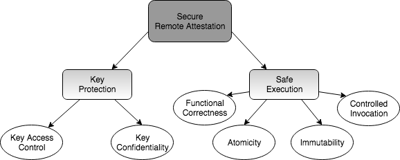
Key Protection:
As mentioned earlier, must not be accessible by regular software running on . To guarantee this, the following features must be correctly implemented:
-
•
P1- Access Control: can only be accessed by SW-Att.
-
•
P2- No Leakage: Neither (nor any function of other than the correctly computed HMAC) can remain in unprotected memory or registers after execution of SW-Att.
-
•
P3- Secure Reset: Any memory tainted by and all registers (including PC) must be erased (or be inaccessible to regular software) after MCU reset. Since a reset might be triggered during SW-Att execution, lack of this property could result in leakage of privileged information about the system state or . Erasure of registers as part of the reset ensures that no state from a previous execution persists. Therefore, the system must return to the default initialization state.
Safe Execution:
Safe execution ensures that is properly and securely used by SW-Att for its intended purpose in the protocol. Safe execution can be divided into four sub-properties:
-
•
P4- Functional Correctness: SW-Att must implement expected behavior of ’s role in the protocol. For instance, if expects a response containing an HMAC of memory in address range , SW-Att implementation should always reply accordingly. Moreover, SW-Att must always finish in finite time, regardless of input size and other parameters.
-
•
P5- Immutability: SW-Att executable must be immutable. Otherwise, malware residing in could modify SW-Att, e.g., to always generate valid measurements or to leak .
-
•
P6- Atomicity: SW-Att execution can not be interrupted. The first reason for atomicity is to prevent leakage of intermediate values in registers and SW-Att’s data memory (including locations that could leak functions of ) during SW-Att execution. This relates to P2 above. The second reason is to prevent roving malware from relocating itself to escape being measured by SW-Att.
-
•
P7- Controlled Invocation: SW-Att must always start from the first instruction and execute until the last instruction. Even though correct implementation of SW-Att is guaranteed by P4, isolated execution of chunks of a correctly implemented code could lead to catastrophic results. Potential ROP attacks could be constructed using gadgets of SW-Att (which, based on P1, have access to ) to compute valid attestation results.
Beyond aforementioned core security properties, in some settings, might need to authenticate ’s attestation requests in order to mitigate potential DoS attacks on . This functionality is also provided (and verified) as an optional feature in the design of VRASED. The differences between the standard design and the one with support for authentication are discussed in Appendix B.
3.3 System Architecture
VRASED architecture is depicted in Figure 3. VRASED is implemented by adding HW-Mod to the MCU architecture, e.g., MSP430. MCU memory layout is extended to include Read-Only Memory (ROM) that houses SW-Att code and used in the HMAC computation. Because and SW-Att code are stored in ROM, we have guaranteed immutability, i.e., P5. VRASED also reserves a fixed part of the memory address space for SW-Att stack. This amounts to of the address space, as discussed in Section 6 222A separate region in RAM is not strictly required. Alternatives and trade-offs are discussed in Section 5. Access control to dedicated memory regions, as well as SW-Att atomic execution are enforced by HW-Mod. The memory backbone is extended to support multiplexing of the new memory regions. HW-Mod takes input signals from the MCU core: , , , , , and . These inputs are used to determine a one-bit signal output, that, when set to , resets the MCU core immediately, i.e., before execution of the next instruction. The output is triggered when HW-Mod detects any violation of security properties 333Resets due to VRASED violations do not give malware advantages as malware can always trigger resets on the unmodified MCU by inducing software faults..
3.4 Verification Approach
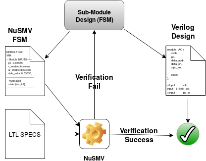
An overview of HW-Mod verification is shown in Figures 4 and 5. We start by formalizing sub-properties discussed in this section using Linear Temporal Logic (LTL) to define invariants that must hold throughout the entire system execution. HW-Mod is implemented as a composition of sub-modules written in the Verilog hardware description language (HDL). Each sub-module implements the hardware responsible for ensuring a given subset of the LTL specifications. Each sub-module is described as an FSM in: (1) Verilog at Register Transfer Level (RTL); and (2) the Model-Checking language SMV [17]. We then use the NuSMV model checker to verify that the FSM complies with the LTL specifications. If verification fails, the sub-module is re-designed.
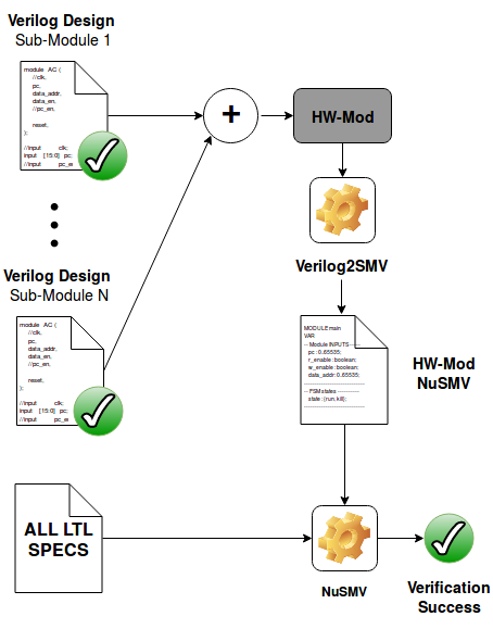
Once each sub-module is verified, they are combined into a single Verilog design. The composition is converted to SMV using the automatic translation tool Verilog2SMV [27]. The resulting SMV is simultaneously verified against all LTL specifications to prove that the final Verilog design for HW-Mod complies with all secure properties.
We clarify that the individual SMV sub-modules’ design and verification steps are not strictly required in the verification pipeline. This is because verifying SMV that is automatically translated from the composition of HW-Mod would suffice. Nevertheless, we design FSMs in SMV first so as to facilitate sub-modules’ development and reasoning with an early additional check before going into their actual implementation and composition in Verilog.
Remark: Automatic conversion of the composition of HW-Mod from Verilog to
SMV rules out the possibility of human mistakes in representing Verilog FSMs as SMV.
For the SW-Att part of VRASED, we use the HMAC-SHA-256 from the HACL* library [51] to compute an authenticated intregrity check of attested memory and received from . This function is formally verified with respect to memory safety, functional correctness, and cryptographic security. However, key secrecy properties (such as clean-up of memory tainted by the key) are not formally verified in HACL* and thus must be ensured by HW-Mod.
As the last step, we prove that the conjunction of the LTL properties guaranteed by HW-Mod and SW-Att implies soundness and security of the architecture. These are formally specified in Section 4.2.
4 Verifying VRASED
In this section we formalize sub-properties. For each sub-property, we represent it as a set of LTL specifications and construct an FSM that is verified to conform to such specifications. Finally, the conjunction of these FSMs is implemented in Verilog HDL and translated to SMV using Verilog2SMV. The generated SMV description for the conjunction is proved to simultaneously hold for all specifications. We also define end-to-end soundness and security goals which are derived from the verified sub-properties (See Appendix A for the proof).
4.1 Notation
To facilitate generic LTL specifications that represent VRASED’s architecture (see Figure 3) we use the following:
-
•
and : first and last physical addresses of the memory region to be attested;
-
•
and : physical addresses of first and last instructions of SW-Att in ROM;
-
•
and : first and last physical addresses of the ROM region where is stored;
-
•
and : first and last physical addresses of the RAM region reserved for SW-Att computation;
-
•
: fixed address that stores the result of SW-Att computation (HMAC);
-
•
: size of HMAC result;
Table 1 uses the above definitions and summarizes the notation used in our LTL specifications throughout the rest of this paper.
To simplify specification of defined security properties, we use to denote a contiguous memory region between and . Therefore, the following equivalence holds:
| (1) |
For example, expression holds when the current value of signal is within and ,
meaning that the MCU is currently executing an instruction in CR, i.e, a SW-Att instruction.
This is because in the notation introduced above: .
FSM Representation. As discussed in Section 3, HW-Mod sub-modules are represented as FSMs that are verified to hold for LTL specifications. These FSMs correspond to the Verilog hardware design of HW-Mod sub-modules. The FSMs are implemented as Mealy machines, where output changes at any time as a function of both the current state and current input values444This is in contrast with Moore machines where the output is defined solely based on the current state.. Each FSM has as inputs a subset of the following signals and wires: , , ,, , , .
Each FSM has only one output, , that indicates whether any security property was violated. For the sake of presentation, we do not explicitly represent the value of the output for each state. Instead, we define the following implicit representation:
-
1.
output is 1 whenever an FSM transitions to the state;
-
2.
output remains 1 until a transition leaving the state is triggered;
-
3.
output is 0 in all other states.
| Notation | Description |
|---|---|
| Current Program Counter value | |
| Signal that indicates if the MCU is reading from memory (1-bit) | |
| Signal that indicates if the MCU is writing to memory (1-bit) | |
| Address for an MCU memory access | |
| Signal that indicates if DMA is currently enabled (1-bit) | |
| Memory address being accessed by DMA, if any | |
| (Code ROM) Memory region where SW-Att is stored: | |
| ( ROM) Memory region where is stored: | |
| (eXclusive Stack) secure RAM region reserved for SW-Att computations: | |
| (MAC RAM) RAM region in which SW-Att computation result is written: . The same region is also used to pass the attestation challenge as input to SW-Att | |
| (Attested Region) Memory region to be attested. Can be fixed/predefined or specified in an authenticated request from : | |
| A 1-bit signal that reboots the MCU when set to logic | |
| A1, A2, …, A7 | Verification axioms (outlined in section 3.1) |
| P1, P2, …, P7 | Properties required for secure (outlined in section 3.2) |
4.2 Formalizing Soundness and Security
We now define the notions of soundness and security. Intuitively, soundness corresponds to computing an integrity ensuring function over memory at time . Our integrity ensuring function is an HMAC computed on memory with a one-time key derived from and . Since SW-Att computation is not instantaneous, soundness must ensure that attested memory does not change during computation of the HMAC. This is the notion of temporal consistency in remote attestation [14]. In other words, the result of SW-Att call must reflect the entire state of the attested memory at the time when SW-Att is called. This notion is captured in LTL by Definition 1.
Definition 1.
End-to-end definition for soundness of computation where M is any AR value and KDF is a secure key derivation function.In Definition 1, captures the time when SW-Att is called (execution of its first instruction). and are the values of and . From this pre-condition, Definition 1 asserts that there is a time in the future when SW-Att computation finishes and, at that time, stores the result of . Note that, to satisfy Definition 1, and in the resulting HMAC must correspond to the values in and , respectively, when SW-Att was called.
security is defined using the security game in Figure 6. It models an adversary (that is a probabilistic polynomial time, ppt, machine) that has full control of the software state of (as the one described in Section 3.1). It can modify at will and call SW-Att a polynomial number of times in the security parameter ( and bit-lengths). However, can not modify SW-Att code, which is stored in immutable memory. The game assumes that does not have direct access to , and only learns after it receives from as part of the attestation request.
Definition 2.
2.1 Security Game (-game): Assumptions: - SW-Att is immutable, and is not known to- is the security parameter and
- denotes the content in at time
- can modify and at will; however, it loses its ability to modify them while SW-Att is running -game: 1. Setup: is given oracle access to SW-Att. 2. Challenge: A random challenge is generated and given to . continues to have oracle access to SW-Att. 3. Response: Eventually, responds with a pair , where is either forged by , or the result of calling SW-Att at some arbitrary time . 4. wins if and only if and . 2.2 Security Definition:
An protocol is considered secure if there is no ppt , polynomial in , capable of winning the game defined in 2.1 with
In the following sections, we define SW-Att functional correctness, LTL specifications 2-10 and formally verify that VRASED’s design guarantees such LTL specifications. We define LTL specifications from the intuitive properties discussed in Section 3.2 and depicted in Figure 2. In Appendix A we prove that the conjunction of such properties achieves soundness (Definition 1) and security (Definition 2). For the security proof, we first show that VRASED guarantees that can never learn with more than negligible probability, thus satisfying the assumption in the security game. We then complete the proof of security via reduction, i.e., show that existence of an adversary that wins the game in Definition 2 implies the existence of an adversary that breaks the conjectured existential unforgeability of HMAC.
Remark: The rest of this section focuses on conveying the intuition behind the specification of LTL sub-properties. Therefore, our references to the MCU machine model are via Axioms A1 - A7 which were described in high level. The interested reader can find an LTL machine model formalizing these notions in Appendix A, where we describe how such machine model is used construct computer proofs for Definitions 1 and 2.
4.3 VRASED SW-Att
To minimize required hardware features, hybrid approaches implement integrity ensuring functions (e.g., HMAC) in software. VRASED’s SW-Att implementation is built on top of HACL*’s HMAC implementation [51]. HACL* code is verified to be functionally correct, memory safe and secret independent. In addition, all memory is allocated on the stack making it predictable and deterministic.
SW-Att is simple, as depicted in Figure 7. It first derives a new unique context-specific key () from the master key () by computing an HMAC-based key derivation function, HKDF [31], on . This key derivation can be extended to incorporate attested memory boundaries if specifies the range (see Appendix B). Finally, it calls HACL*’s HMAC, using key as the HMAC key. and specify the memory range to be attested ( in our notation). We emphasize that SW-Att resides in ROM, which guarantees P5 under the assumption of no hardware attacks. Moreover, as discussed below, HW-Mod enforces that no other software running on can access memory allocated by SW-Att code, e.g., buffer allocated in line 2 of Figure 7.
HACL*’s verified HMAC is the core for guaranteeing P4 (Functional Correctness) in VRASED’s design. SW-Att functional correctness means that, as long as the memory regions storing values used in SW-Att computation (, , and ) do not change during its computation, the result of such computation is the correct HMAC. This guarantee can be formally expressed in LTL as in Definition 3. We note that since HACL*’s HMAC functional correctness is specified in F*, instead of LTL, we manually convert its guarantees to the LTL expressed by Definition 3. By this definition, the value in does not need to remain the same, as it will eventually be overwritten by the result of SW-Att computation.
Definition 3.
SW-Att functional correctness where M is any arbitrary value for AR.In addition, some HACL* properties, such as stack-based and deterministic memory allocation, are used in alternative designs of VRASED to ensure P2 – see Section 5.
Functional correctness implies that the HMAC implementation conforms to its published standard specification on all possible inputs, retaining the specification’s cryptographic security. It also implies that HMAC executes in finite time. Secret independence ensures that there are no branches taken as a function of secrets, i.e., and key in Figure 7. This mitigates leakage via timing side-channel attacks. Memory safety guarantees that implemented code is type safe, meaning that it never reads from, or writes to: invalid memory locations, out-of-bounds memory, or unallocated memory. This is particularly important for preventing ROP attacks, as long as P7 (controlled invocation) is also preserved555Otherwise, even though the implementation is memory-safe and correct as a whole, chunks of a memory-safe code could still be used in ROP attacks..
Having all memory allocated on the stack allows us to either: (1) confine SW-Att execution to a fixed size protected memory region inaccessible to regular software (including malware) running on ; or (2) ensure that SW-Att stack is erased before the end of execution. Note that HACL* does not provide stack erasure, in order to improve performance. Therefore, P2 does not follow from HACL* implementation. However, erasure before SW-Att terminates must be guaranteed. Recall that VRASED targets low-end MCUs that might run applications on bare-metal and thus can not rely on any OS features.
As discussed above, even though HACL* implementation guarantees P4 and storage in ROM guarantees P5, these must be combined with P6 and P7 to provide safe execution. P6 and P7 – along with the key protection properties (P1, P2, and P3) – are ensured by HW-Mod, which are described next.
4.4 Key Access Control (HW-Mod)
If malware manages to read from ROM, it can reply to with a forged result.
HW-Mod access control (AC) sub-module enforces that can only be accessed by SW-Att (P1).
4.4.1 LTL Specification
The invariant for key access control (AC) is defined in LTL Specification (2). It stipulates that system must transition to the state whenever code from outside tries to read from within the key space.
| (2) |
4.4.2 Verified Model
Figure 8 shows the FSM implemented by the AC sub-module which is verified to hold for LTL Specification 2. This FSM has two states: Run and Reset. It outputs when the AC sub-module transitions to state Reset. This implies a hard-reset of the MCU. Once the reset process completes, the system leaves the Reset state.
4.5 Atomicity and Controlled Invocation (HW-Mod)
In addition to functional correctness, safe execution of attestation code requires immutability (P5), atomicity (P6), and controlled invocation (P7). P5 is achieved directly by placing SW-Att in ROM. Therefore, we only need to formalize invariants for the other two properties: atomicity and controlled execution.
4.5.1 LTL Specification
To guarantee atomic execution and controlled invocation, LTL Specifications (3), (4) and (5) must hold:
| (3) |
| (4) |
| (5) |
LTL Specification (3) enforces that the only way for SW-Att execution to terminate is through its last instruction: . This is specified by checking current and next values using LTL neXt operator. In particular, if current value is within SW-Att region, and next value is out of SW-Att region, then either current value is the address of the last instruction in SW-Att (), or is triggered in the next cycle. Also, LTL Specification (4) enforces that the only way for to enter SW-Att region is through the very first instruction: . Together, these two invariants imply P7: it is impossible to jump into the middle of SW-Att, or to leave SW-Att before reaching the last instruction.
P6 is satisfied through LTL Specification (5). Atomicity could be violated by interrupts. However, LTL Specification (5) prevents an interrupt to happen while SW-Att is executing. Therefore, if interrupts are not disabled by software running on before calling SW-Att, any interrupt that might violate SW-Att atomicity will cause an MCU .
4.5.2 Verified Model
Figure 9 presents a verified model for atomicity and controlled invocation enforcement. The FSM has five states. Two basic states and represent moments when points to an address: (1) outside , and (2) within , respectively, not including the first and last instructions of SW-Att. Another two: and represent states when points to the first and last instructions of SW-Att, respectively. Note that the only possible path from to is through . Similarly, the only path from to is through . The FSM transitions to the state whenever: (1) any sequence of values for does not obey the aforementioned conditions; or (2) is logical 1 while exeucuting SW-Att.
4.6 Key Confidentiality (HW-Mod)
To guarantee secrecy of and thus satisfy P2, VRASED must enforce the following:
-
1.
No leaks after attestation: any registers and memory accessible to applications must be erased at the end of each attestation instance, i.e., before application execution resumes.
-
2.
No leaks on reset: since a reset can be triggered during attestation execution, any registers and memory accessible to regular applications must be erased upon reset.
Per Axiom A4, all registers are zeroed out upon reset and at boot time. Therefore, the only time when register clean-up is necessary is at the end of SW-Att. Such clean-up is guaranteed by the Callee-Saves-Register convention: Axiom A6.
Nonetheless, the leakage problem remains because of RAM allocated by SW-Att. Thus, we must guarantee that is not leaked through "dead" memory, which could be accessed by application (possibly, malware) after SW-Att terminates. A simple and effective way of addressing this issue is by reserving a separate secure stack in RAM that is only accessible (i.e., readable and writable) by attestation code. All memory allocations by SW-Att must be done on this stack, and access control to the stack must be enforced by HW-Mod. As discussed in Section 6, the size of this stack is constant – KBytes. This corresponds to of MSP430 16-bit address space. We discuss VRASED variants that do not require a reserved stack and trade-offs between them in Section 5.
4.6.1 LTL Specification
Recall that denote a contiguous secure memory region reserved for exclusive access by SW-Att. LTL Specification for the secure stack sub-module is as follows:
| (6) |
We also want to prevent attestation code from writing into application memory. Therefore, it is only allowed to write to the designated fixed region for the HMAC result ().
| (7) |
In summary, invariants (6) and (7) enforce that only attestation code can read from/write to the secure reserved stack and that attestation code can only write to regular memory within the space reserved for the HMAC result. If any of these conditions is violated, the system resets.
4.6.2 Verified Model
4.7 DMA Support
So far, we presented a formalization of HW-Mod sub-modules under the assumption that DMA is either not present or disabled on . However, when present, a DMA controller can access arbitrary memory regions. Such memory access is performed concurrently in the memory backbone and without MCU intervention, while the MCU executes regular instructions.
DMA data transfer is performed using dedicated memory buses, e.g., and . Hence, regular memory access control (based on monitoring ) does not apply to memory access by DMA controller. Thus, if DMA controller is compromised, it may lead to violation of P1 and P2 by directly reading and values in the attestation stack, respectively. In addition, it can assist -resident malware to escape detection by either copying it out of the measurement range or deleting it, which results in a violation of P6.
4.7.1 LTL Specification
We introduce three additional LTL Specifications to protect against aforementioned attacks. First, we enforce that DMA cannot access .
| (8) |
Similarly, LTL Specification for preventing DMA access to the attestation stack is defined as:
| (9) |
Finally, invariant (10) specifies that DMA must be always disabled while is in SW-Att region. This prevents DMA controller from helping malware escape during attestation.
| (10) |
4.7.2 Verified Model
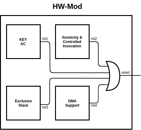
4.8 HW-Mod Composition
Thus far, we designed and verified individual HW-Mod sub-modules according to the methodology in Section 3.4 and illustrated in Figure 4. We now follow the workflow of Figure 5 to combine the sub-modules into a single Verilog module. Since each sub-module individually guarantees a subset of properties P1–P7, the composition is simple: the system must reset whenever any sub-module reset is triggered. This is implemented by a logical OR of sub-modules reset signals. The composition is shown in Figure 12.
To verify that all LTL specifications still hold for the composition, we use Verilog2SMV [27] to translate HW-Mod to SMV and verify SMV for all of these specifications simultaneously.
4.9 Secure Reset (HW-Mod)
Finally, we define an LTL Specification for secure reset (P3). According to Axiom A4, all registers (including ) are set to on reset. However, the reset routine implemented by the MCU might take several clock cycles. Ensuring that until the point when registers are wiped is important in order to guarantee that is not leaked through registers after a reset. That is because some part of might remain in some of the registers if a reset happens during SW-Att execution.
4.9.1 LTL Specification
To guarantee that the reset signal is active for long enough so that the MCU reset finishes and all registers are cleaned-up, it must hold that:
| (11) |
Invariant (11) states: when reset signal is triggered, it can only be released after . Transition from state in all sub-modules presented in this section already takes this invariant into account. Thus, HW-Mod composition also verifies LTL Specification (11).
5 Alternative Designs
We now discuss alternative designs for VRASED that guarantee verified properties without requiring a separate secure stack region for SW-Att operations. Recall that HW-Mod enforces that only SW-Att can access this stack. Since memory usage in HACL* HMAC is deterministic, the size of the separate stack can be pre-determined – bytes. Even though resulting in overall (HW and SW) design simplicity, dedicating of addressable memory to secure might not be desirable. Therefore, we consider several alternatives. In Section 6 the costs involved with these alternatives are quantified and compared to the standard design of VRASED.
5.1 Erasure on SW-Att
The most intuitive alternative to a reserved secure stack (which prevents accidental key leakage by SW-Att) is to encode corresponding properties into the HACL* implementation and proof. Specifically, it would require extending the HACL* implementation to zero out all allocated memory before every function return. In addition, to retain verification of P2 (in Section 3.2) and ensure no leakage, HACL*-verified properties must be extended to incorporate memory erasure. This is not yet supported in HACL* and doing so would incur a slight performance overhead. However, the trade-off between performance and RAM savings might be worthwhile.
At the same time, we note that, even with verified erasure as a part of SW-Att, P2 is still not guaranteed if the MCU does not guarantee erasure of the entire RAM upon boot. This is necessary in order to consider the case when re-boots in the middle of SW-Att execution. Without a reserved stack, might persist in RAM. Since the memory range for SW-Att execution is not fixed, hardware support is required to bootstrap secure RAM erasure before starting any software execution. In fact, such support is necessary for all approaches without a separate secure stack.
5.2 Compiler-Based Clean-Up
While stack erasure in HACL* would integrate nicely with the overall proof of SW-Att, the assurance would be at the language abstraction level, and not necessarily at the machine level. The latter would require additional assumptions about the compilation tool chain. We could also consider performing stack erasure directly in the compiler. In fact, a recent proposal to do exactly that was made in zerostack [44], an extension to Clang/LLVM. In case of VRASED, this feature could be used on unmodified HACL* (at compilation time), to add instructions to erase the stack before the return of each function enabling P2, assuming the existence of a verified RAM erasure routine upon boot. We emphasize that this approach may increase the compiler’s trusted code base. Ideally, it should be implemented and formally verified as part of a verified compiler suite, such as CompCert [32].
| Method | RAM Erasure Required Upon Boot? | FPGA Hardware | Verilog LoC | Memory (byte) | Time to attest 4KB | ||||
|---|---|---|---|---|---|---|---|---|---|
| LUT | Reg | Cell | ROM | Sec. RAM | CPU cycles | ms (at 8MHz) | |||
| Core (Baseline) | N/A | 1842 | 684 | 3044 | 4034 | 0 | 0 | N/A | N/A |
| Secure Stack (Section 4) | No | 1964 | 721 | 3237 | 4621 | 4500 | 2332 | 3601216 | 450.15 |
| Erasure on SW-Att (Section 5.1) | Yes | 1954 | 717 | 3220 | 4516 | 4522 | 0 | 3613283 | 451.66 |
| Compiler-based Clean-up (Section 5.2) 666As mentioned in Section 5.2, there is no formally verified msp430 compiler capable of performing stack erasure. Thus, we estimate overhead of this approach by manually inserting code required for erasing the stack in SW-Att. | Yes | 1954 | 717 | 3220 | 4516 | 4522 | 0 | 3613283 | 451.66 |
| Double-HMAC Call (Section 5.3) | Yes | 1954 | 717 | 3220 | 4516 | 4570 | 0 | 7201605 | 900.20 |
5.3 Double-HMAC Call
Finally, complete stack erasure could also be achieved directly using currently verified HACL* properties, without any further modifications. This approach involves invoking HACL* HMAC function a second time, after the computation of the actual HMAC. The second "dummy" call would use the same input data, however, instead of using , an independent constant, such as , would be used as the HMAC key.
Recall that HACL* is verified to only allocate memory on the stack in a deterministic manner. Also, due to HACL*’s verified properties that mitigate side-channels, software flow does not change based on the secret key. Therefore, this deterministic allocation implies that, for inputs of the same size, any variable allocated by the first "real" HMAC call (tainted by ), would be overwritten by the corresponding variable in the second "dummy" call. Note that the same guarantee discussed in Section 5.1 is provided here and secure RAM erasure at boot would still be needed for the same reasons. Admittedly, this double-HMAC approach would consume twice as many CPU cycles. Still, it might be a worthwhile trade-off, especially, if there is memory shortage and lack of previously discussed HACL* or compiler extension.
6 Evaluation
We now discuss implementation details and evaluate VRASED’s overhead and performance. Section 6.2 reports on verification complexity. Section 6.3 discusses performance in terms of time and space complexity as well as its hardware overhead. We also provide a comparison between VRASED and other architectures targeting low-end devices, namely SANCUS [37] and SMART [20], in Section 6.4.
6.1 Implementation
As mentioned earlier, we use OpenMSP430 [21] as an open core implementation of the MSP430 architecture. OpenMSP430 is written in the Verilog hardware description language (HDL) and can execute software generated by any MSP430 toolchain with near cycle accuracy. We modified the standard OpenMSP430 to implement the hardware architecture presented in Section 3.3, as shown in Figure 3. This includes adding ROM to store and SW-Att, adding HW-Mod, and adapting the memory backbone accordingly. We use Xilinx Vivado [49] – a popular logic synthesis tool – to synthesize an RTL description of HW-Mod into hardware in FPGA. FPGA synthesized hardware consists of a number of logic cells. Each consists of Look-Up Tables (LUTs) and registers; LUTs are used to implement combinatorial boolean logic while registers are used for sequential logic elements, i.e., FSM states and data storage. We compiled SW-Att using the native msp430-gcc [45] and used Linker scripts to generate software images compatible with the memory layout of Figure 3. Finally, we evaluated VRASED on the FPGA platform targeting Artix-7 [50] class of devices.
6.2 Verification Results
As discussed in Section 3.2, VRASED’s verification consists of properties P1–P7. P5 is achieved directly by executing SW-Att from ROM. Meanwhile, HACL* HMAC verification implies P4. All other properties are automatically verified using NuSMV model checker. Table 3 shows the verification results of VRASED’s HW-Mod composition as well as results for individual sub-modules. It shows that VRASED successfully achieves all the required security properties. These results also demonstrate feasibility of our verification approach, since the verification process – running on a commodity desktop computer – consumes only small amount of memory and time: MB and sec, respectively, for all properties.
6.3 Performance and Hardware Cost
We now report on VRASED’s performance considering the standard design (described in Section 4) and alternatives
discussed in Section 5.
We evaluate the hardware footprint, memory (ROM and secure RAM), and run-time.
Table 2 summarizes the results.
Hardware Footprint.
The secure stack approach adds around 434 lines of code in Verilog HDL.
This corresponds to around 20% of the code in the original OpenMSP430 core.
In terms of synthesized hardware, it requires 122 (6.6%) and 19 (5.4%) additional LUTs and registers respectively.
Overall, VRASED contains 193 logic cells more than the unmodified OpenMSP430 core, corresponding to a 6.3% increase.
Memory.
VRASED requires 4.5KB of ROM;
most of which (96%) is for storing HACL* HMAC-SHA256 code.
The secure stack approach has the smallest ROM size, as it does not need to perform a memory clean-up in software.
However, this advantage is attained at the price of requiring 2.3KBytes of reserved RAM.
This overhead corresponds to 3.5% of MSP430 16-bit address space.
Attestation Run-time.
Attestation run-time is dominated by the time it takes to compute the HMAC of ’s memory.
The secure stack, erasure on SW-Att and compiler-based clean-up approaches take roughly .45 to attest
4 of RAM on an MSP430 device with a clock frequency at 8MHz.
Whereas, the double MAC approach requires invoking the HMAC function twice, leading its run-time to be roughly two times slower.
Discussion.
We consider VRASED’s overhead to be affordable.
The additional hardware, including registers, logic gates and exclusive memory, resulted in only a 3-6% increase.
The number of cycles required by SW-Att exhibits a linear increase with the size of attested memory.
As MSP430 typically runs at 8-25MHz, attestation of the entire RAM on a typical MSP430 can be computed in less than a second.
VRASED’s is relatively cheap to the .
As a point of comparison we can consider a common cryptographic primitive such as the Curve25519 Elliptic-Curve Diffie-Hellman (ECDH) key exchange.
A single execution of an optimized version of such protocol on MSP430 has been reported to take million cycles [23].
As Table 2 shows, attestation of KBytes (typical size of RAM in some MSP430 models) can be computed three times faster.
6.4 Comparison with Other Low-End Architectures
We here compare VRASED’s overhead with two widely known architectures targeting low-end embedded systems: SMART [20] and SANCUS [37]. We emphasize, however, that both SMART and SANCUS were designed in an ad hoc manner. Thus, they can not be formally verified and do not provide any guarantees offered by VRASED’s verified architecture. Nevertheless, it is considered important to contrast VRASED’s cost with such architectures to demonstrate its affordability.
Table 4 presents a comparison between features offered and required by aforementioned architectures. SANCUS is, to the best of our knowledge, the cheapest pure HW-based architecture, while SMART is a minimal HW/SW co-design. Since SANCUS’s routine is implemented entirely in HW, it does not require ROM to store the SW implementation of the integrity ensuring function. VRASED implements a MAC with digest sizes of 256-bits. SMART and SANCUS, on the other hand, use SHA1-based MAC and SPONGNET-128/128/8 [7], respectively. Such MACs do not offer strong collision resistance due to the small digest sizes (and known collisions). Of the three architectures, VRASED is the only one secure in the presence of DMA and the only one to be rigorously specified and formally verified.
| VRASED | SMART | SANCUS | |
|---|---|---|---|
| Design Type | Hybrid (HW/SW) | Hybrid (HW/SW) | Pure HW |
| function | HMAC-SHA256 | HMAC-SHA1 | SPONGNET-128/128/8 |
| ROM for code | Yes | Yes | No |
| DMA Support | Yes | No | No |
| Formally Verified | Yes | No | No |
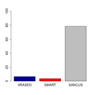
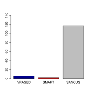
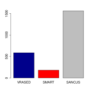
Figure 13 presents a quantitative comparison between the architectures. It considers additional overhead in relation to the latest version of the unmodified OpenMSP430 (Available at [21]). Compared to VRASED, SANCUS requires more Look-Up Tables, more registers, and its (unverified) TCB is 2.5 times larger in lines of Verilog code. This comparison demonstrates the cost of relying on a HW-only approach even when designed for minimality. SMART’s overhead is slightly smaller than that of VRASED due to lack of DMA support. In terms of attestation execution time, SMART is the slowest, requiring 9.2M clock cycles to attest 4KB of memory. SANCUS achieves the fastest attestation time (1.3M cycles) due to the HW implementation of SPONGNET-128/128/8. VRASED sits in between the two with a total attestation time of 3.6M cycles.

7 Related Work
We are unaware of any previous work that yielded a formally verified design ( architectures are overviewed in Section 2.1). To the best of our knowledge, VRASED is the first verification of a security service implemented as HW/SW co-design. Nevertheless, formal verification has been widely used as the de facto means to guarantee that a system is free of implementation errors and bugs. In recent years, several efforts focused on verifying security-critical systems.
In terms of cryptographic primitives, Hawblitzel et al. [22] verified new implementations of SHA, HMAC, and RSA. Beringer et al.[4] verified the Open-SSL SHA-256 implementation. Bond et al. [8] verified an assembly implementation of SHA-256, Poly1305, AES and ECDSA. More recently, Zinzindohoué, et al. [51] developed HACL*, a verified cryptographic library containing the entire cryptographic API of NaCl [5]. As discussed earlier, HACL*’s verified HMAC forms the core of VRASED’s software component.
Larger security-critical systems have also been successfully verified. For example, Bhargavan [6] implemented the TLS protocol with verified cryptographic security. CompCert[32] is a C compiler that is formally verified to preserve C code semantics in generated assembly code. Klein et al. [28] designed and proved functional correctness of seL4 – the first verified general-purpose microkernel. More recently, Tuncay et al. verified a design for Android OS App permissions model [47].
The importance of verifying has been recently acknowledged by Lugou et al. [35], which discussed methodologies for specifically verifying HW/SW co-designs. A follow-on result proposed the SMASH-UP tool [36]. By modeling a hardware abstraction, SMASH-UP allows automatic conversion of assembly instructions to the effects on hardware representation. Similarly, Cabodi et al. [12, 11] discussed the first steps towards formalizing hybrid properties. However, none of these results yielded a fully verified (and publicly available) architecture, such as VRASED.
8 Conclusion
This paper presents VRASED – the first formally verified method that uses a verified cryptographic software implementation and combines it with a verified hardware design to guarantee correct implementation of security properties. VRASED is also the first verified security service implemented as a HW/SW co-design. VRASED was designed with simplicity and minimality in mind. It results in efficient computation and low hardware cost, realistic even for low-end embedded systems. VRASED’s practicality is demonstrated via publicly available implementation using the low-end MSP430 platform. The design and verification methodology presented in this paper can be extended to other MCU architectures. We believe that this work represents an important and timely advance in embedded systems security, especially, with the rise of heterogeneous ecosystems of (inter-)connected IoT devices.
The most natural direction for future work is to adapt VRASED to other MCU architectures. Such an effort could follow the same verification methodology presented in this paper. It would involve: (1) mapping MCUs specifications to a set of axioms (as we did for MSP430 in Section 3), and (2) adapting the proofs by modifying the LTL Specifications and hardware design (as in in Section 4) accordingly. A second direction is to extend VRASED’s capabilities to include and verify other trusted computing services such as secure updates, secure deletion, and remote code execution. It would also be interesting to verify and implement other designs with different requirements and trade-offs, such as software- and hardware-based techniques. In the same vein, one promising direction would be to verify HYDRA architecture [19], which builds on top of the formally verified seL4 [28] microkernel. Finally, the optimization of VRASED’s HMAC, with respect to computation and memory allocation, while retaining its verified properties, is an interesting open problem.
References
- [1] VRASED source code. https://github.com/sprout-uci/vrased, 2019.
- [2] M. Antonakakis, T. April, M. Bailey, M. Bernhard, E. Bursztein, J. Cochran, Z. Durumeric, J. A. Halderman, L. Invernizzi, M. Kallitsis, et al. Understanding the mirai botnet. In USENIX Security Symposium, 2017.
- [3] Arm Ltd. Arm TrustZone, 2018.
- [4] L. Beringer, A. Petcher, Q. Y. Katherine, and A. W. Appel. Verified correctness and security of OpenSSL HMAC. In USENIX, 2015.
- [5] D. J. Bernstein, T. Lange, and P. Schwabe. The security impact of a new cryptographic library. In International Conference on Cryptology and Information Security in Latin America, 2012.
- [6] K. Bhargavan, C. Fournet, M. Kohlweiss, A. Pironti, and P.-Y. Strub. Implementing TLS with verified cryptographic security. In SP, 2013.
- [7] A. Bogdanov, M. Knezevic, G. Leander, D. Toz, K. Varici, and I. Verbauwhede. Spongent: The design space of lightweight cryptographic hashing. IEEE Transactions on Computers, 62, 2013.
- [8] B. Bond, C. Hawblitzel, M. Kapritsos, K. R. M. Leino, J. R. Lorch, B. Parno, A. Rane, S. Setty, and L. Thompson. Vale: Verifying high-performance cryptographic assembly code. In USENIX, 2017.
- [9] F. Brasser, B. El Mahjoub, A.-R. Sadeghi, C. Wachsmann, and P. Koeberl. TyTAN: tiny trust anchor for tiny devices. In DAC. ACM.
- [10] F. Brasser, A.-R. Sadeghi, and G. Tsudik. Remote attestation for low-end embedded devices: the prover’s perspective. In DAC, 2016.
- [11] G. Cabodi, P. Camurati, S. F. Finocchiaro, C. Loiacono, F. Savarese, and D. Vendraminetto. Secure embedded architectures: Taint properties verification. In DAS, 2016.
- [12] G. Cabodi, P. Camurati, C. Loiacono, G. Pipitone, F. Savarese, and D. Vendraminetto. Formal verification of embedded systems for remote attestation. WSEAS Transactions on Computers, 14:760–769, 2015.
- [13] X. Carpent, K. Eldefrawy, N. Rattanavipanon, A.-R. Sadeghi, and G. Tsudik. Reconciling remote attestation and safety-critical operation on simple iot devices. In 2018 55th ACM/ESDA/IEEE Design Automation Conference (DAC), pages 1–6. IEEE, 2018.
- [14] X. Carpent, K. Eldefrawy, N. Rattanavipanon, and G. Tsudik. Temporal consistency of integrity-ensuring computations and applications to embedded systems security. In ASIACCS, 2018.
- [15] X. Carpent, N. Rattanavipanon, and G. Tsudik. ERASMUS: Efficient remote attestation via self-measurement for unattended settings. In Design, Automation and Test in Europe (DATE), 2018.
- [16] X. Carpent, N. Rattanavipanon, and G. Tsudik. Remote attestation of iot devices via SMARM: Shuffled measurements against roving malware. In IEEE International Symposium on Hardware Oriented Security and Trust (HOST), 2018.
- [17] A. Cimatti, E. Clarke, E. Giunchiglia, F. Giunchiglia, M. Pistore, M. Roveri, R. Sebastiani, and A. Tacchella. NuSMV 2: An opensource tool for symbolic model checking. In International Conference on Computer Aided Verification, pages 359–364. Springer, 2002.
- [18] A. Duret-Lutz, A. Lewkowicz, A. Fauchille, T. Michaud, E. Renault, and L. Xu. Spot 2.0—a framework for ltl and -automata manipulation. In International Symposium on Automated Technology for Verification and Analysis, pages 122–129. Springer, 2016.
- [19] K. Eldefrawy, N. Rattanavipanon, and G. Tsudik. HYDRA: hybrid design for remote attestation (using a formally verified microkernel). In Wisec. ACM, 2017.
- [20] K. Eldefrawy, G. Tsudik, A. Francillon, and D. Perito. SMART: Secure and minimal architecture for (establishing dynamic) root of trust. In NDSS. Internet Society, 2012.
- [21] O. Girard. openMSP430, 2009.
- [22] C. Hawblitzel, J. Howell, J. R. Lorch, A. Narayan, B. Parno, D. Zhang, and B. Zill. Ironclad apps: End-to-end security via automated full-system verification. In OSDI, volume 14, pages 165–181, 2014.
- [23] G. Hinterwälder, A. Moradi, M. Hutter, P. Schwabe, and C. Paar. Full-size high-security ECC implementation on MSP430 microcontrollers. In International Conference on Cryptology and Information Security in Latin America, pages 31–47. Springer, 2014.
- [24] A. Ibrahim, A.-R. Sadeghi, and S. Zeitouni. SeED: secure non-interactive attestation for embedded devices. In ACM Conference on Security and Privacy in Wireless and Mobile Networks (WiSec), 2017.
- [25] T. Instruments. Msp430 ultra-low-power sensing & measurement mcus. http://www.ti.com/microcontrollers/msp430-ultra-low-power-mcus/overview.html.
- [26] Intel. Intel Software Guard Extensions (Intel SGX).
- [27] A. Irfan, A. Cimatti, A. Griggio, M. Roveri, and R. Sebastiani. Verilog2SMV: A tool for word-level verification. In Design, Automation & Test in Europe Conference & Exhibition (DATE), 2016, pages 1156–1159. IEEE, 2016.
- [28] G. Klein, K. Elphinstone, G. Heiser, J. Andronick, D. Cock, P. Derrin, D. Elkaduwe, K. Engelhardt, R. Kolanski, M. Norrish, T. Sewell, H. Tuch, and S. Winwood. seL4: Formal verification of an OS kernel. In Proceedings of the ACM SIGOPS 22Nd Symposium on Operating Systems Principles, SOSP ’09, pages 207–220, New York, NY, USA, 2009. ACM.
- [29] P. Koeberl, S. Schulz, A.-R. Sadeghi, and V. Varadharajan. TrustLite: A security architecture for tiny embedded devices. In EuroSys. ACM, 2014.
- [30] X. Kovah, C. Kallenberg, C. Weathers, A. Herzog, M. Albin, and J. Butterworth. New results for timing-based attestation. In Proceedings of the IEEE Symposium on Research in Security and Privacy. IEEE Computer Society Press, 2012.
- [31] H. Krawczyk and P. Eronen. HMAC-based extract-and-expand key derivation function (HKDF). Internet Request for Comment RFC 5869, Internet Engineering Task Force, May 2010.
- [32] X. Leroy. Formal verification of a realistic compiler. Communications of the ACM, 52(7):107–115, 2009.
- [33] Y. Li, Y. Cheng, V. Gligor, and A. Perrig. Establishing software-only root of trust on embedded systems: Facts and fiction. In Security Protocols—22nd International Workshop, 2015.
- [34] Y. Li, J. M. McCune, and A. Perrig. Viper: Verifying the integrity of peripherals’ firmware. In CCS. ACM, 2011.
- [35] F. Lugou, L. Apvrille, and A. Francillon. Toward a methodology for unified verification of hardware/software co-designs. Journal of Cryptographic Engineering, 2016.
- [36] F. Lugou, L. Apvrille, and A. Francillon. Smashup: a toolchain for unified verification of hardware/software co-designs. Journal of Cryptographic Engineering, 7(1):63–74, 2017.
- [37] J. Noorman, J. V. Bulck, J. T. Mühlberg, F. Piessens, P. Maene, B. Preneel, I. Verbauwhede, J. Götzfried, T. Müller, and F. Freiling. Sancus 2.0: A low-cost security architecture for iot devices. ACM Trans. Priv. Secur., 20(3):7:1–7:33, July 2017.
- [38] I. D. O. Nunes, G. Dessouky, A. Ibrahim, N. Rattanavipanon, A.-R. Sadeghi, and G. Tsudik. Towards systematic design of collective remote attestation protocols. In ICDCS, 2019.
- [39] D. Perito and G. Tsudik. Secure code update for embedded devices via proofs of secure erasure. In ESORICS, 2010.
- [40] J. Protzenko, J.-K. Zinzindohoué, A. Rastogi, T. Ramananandro, P. Wang, S. Zanella-Béguelin, A. Delignat-Lavaud, C. Hriţcu, K. Bhargavan, C. Fournet, et al. Verified low-level programming embedded in f. Proceedings of the ACM on Programming Languages, 2017.
- [41] S. Ravi, A. Raghunathan, and S. Chakradhar. Tamper resistance mechanisms for secure embedded systems. In VLSI Design, 2004. Proceedings. 17th International Conference on, pages 605–611. IEEE, 2004.
- [42] A. Seshadri, M. Luk, A. Perrig, L. van Doorn, and P. Khosla. Scuba: Secure code update by attestation in sensor networks. In ACM workshop on Wireless security, 2006.
- [43] A. Seshadri, M. Luk, E. Shi, A. Perrig, L. van Doorn, and P. Khosla. Pioneer: Verifying code integrity and enforcing untampered code execution on legacy systems. ACM SIGOPS Operating Systems Review, December 2005.
- [44] L. Simon, D. Chisnall, and R. Anderson. What you get is what you C: Controlling side effects in mainstream C compilers. In Proceedings of the Third IEEE European Symposium on Security and Privacy (EuroSP), London, UK, Apr. 2018. ACM SIGOPS.
- [45] Texas Instruments. MSP430 GCC user’s guide, 2016.
- [46] Trusted Computing Group. Trusted platform module (tpm), 2017.
- [47] G. S. Tuncay, S. Demetriou, K. Ganju, and C. A. Gunter. Resolving the predicament of Android custom permissions. In ISOC Network and Distributed Systems Security Symposium (NDSS), 2018.
- [48] J. Vijayan. Stuxnet renews power grid security concerns. http://www.computerworld.com/article/2519574/security0/stuxnet-renews-power-grid-security-concerns.html, june 2010.
- [49] Xilinx. Vivado design suite user guide, 2017.
- [50] Xilinx Inc. Artix-7 FPGA family, 2018.
- [51] J.-K. Zinzindohoué, K. Bhargavan, J. Protzenko, and B. Beurdouche. Hacl*: A verified modern cryptographic library. In Proceedings of the 2017 ACM SIGSAC Conference on Computer and Communications Security, pages 1789–1806. ACM, 2017.
APPENDIX
Appendix A Soundness and Security Proofs
A.1 Proof Strategy
We present the proofs for soundness (Definition 1) and security (Definition 2). Soundness is proved entirely via LTL equivalences. In the proof of security we first show, via LTL equivalences, that VRASED guarantees that adversary can never learn with more than negligible probability. We then prove security by showing a reduction from HMAC existential unforgeability to security. In other words, we show that existence of that breaks VRASED implies existence of HMAC- able to break conjectured existential unforgeability of HMAC. The full machine-checked proofs for the LTL equivalences (using Spot 2.0 [18] proof assistant) discussed in the remainder of this section are available in [1].
A.2 Machine Model
To prove that VRASED’s design satisfies end-to-end definitions of soundness and security for , we start by formally defining (in LTL) memory and execution models corresponding to the architecture introduced in Section 3.
Definition 4 (Memory model).
1. is stored in ROM 2. SW-Att is stored in ROM 3. , , , , and are non-overlapping memory regionsThe memory model in Definition 4 captures that and are ROM regions, and are thus immutable. Hence, the values stored in those regions always correspond to and SW-Att code, respectively. Finally, the memory model states that , , , , and are disjoint regions in the memory layout, corresponding to the architecture in Figure 3.
Definition 5 (Execution model).
1. Modify_Mem() 2. Read_Mem() 3. InterruptOur execution model, in Definition 5, translates MSP430 behavior by capturing the effects on the processor signals when reading and writing from/to memory. We do not model the effects of instructions that only modify register values (e.g., ALU operations, such as and ) because they are not necessary in our proofs.
The execution model defines that a given memory address can be modified in two cases: by a CPU instruction or by DMA. In the first case, the signal must be on and must contain the memory address being accessed. In the second case, signal must be on and must contain the address being modified by DMA. The requirements for reading from a given address are similar, except that instead of , must be on. Finally, the execution model also captures the fact that an interrupt implies setting the signal to 1.
A.3 Soundness Proof
The proof follows from SW-Att functional correctness (expressed by Definition 3) and LTL specifications 3, 5, 7, and 10
Theorem 1.
VRASED is sound according to Definition 1.
Proof.
∎
The formal computer proof for Theorem 1 can be found in [1]. Due to space limitations, we only provide some intuition, by splitting the proof into two parts. First, SW-Att functional correctness (Definition 3) would imply Theorem 1 if , , never change and an interrupt does not happen during SW-Att computation. However, memory model Definitions 4.1 and 4.2 already guarantee that and never change. Also, LTL 5 states that an interrupt cannot happen during SW-Att computation, otherwise the device resets. Therefore, it remains for us to show that does not change during SW-Att computation. This is stated in Lemma 1.
Lemma 1.
Temporal Consistency – Attested memory does not change during SW-Att computationIn turn, Lemma 1 can be proved by:
| (12) |
The reasoning for Equation 12 is as follows:
-
•
prevents the CPU from stopping execution of SW-Att before its last instruction.
-
•
guarantees that the only memory regions written by the CPU during SW-Att execution are and , which do not overlap with .
-
•
prevents DMA from writing to memory during SW-Att execution.
Therefore, there are no means for modifying during SW-Att execution, implying Lemma 1. As discussed above, it is easy to see that:
| (13) |
A.4 Security Proof
Recall the definition of security in the game in Figure 6. The game makes two key assumptions:
-
1.
SW-Att call results in a temporally consistent HMAC of using a key derived from and . This is already proved by VRASED’s soundness.
-
2.
never learns with more than negligible probability.
Lemma 2.
Key confidentiality – can not be accessed directly by untrusted software () and any memory written to by SW-Att can never be read by untrusted software.By proving that VRASED’s design satisfies assumptions 1 and 2, we show that the capabilities of untrusted software (any DMA or CPU software other than SW-Att) on are equivalent to the capabilities of in -game. Therefore, we still need to prove item 2 before we can use such game to prove VRASED’s security. The proof of ’s inability to learn with more than negligible probability is facilitated by A6 - Callee-Saves-Register convention stated in Section 3. A6 directly implies no leakage of information through registers on the return of SW-Att. This is because, before the return of a function, registers must be restored to their state prior to the function call. Thus, untrusted software can only learn (or any function of ) through memory. However, if untrusted software can never read memory written by SW-Att, it never learns anything about (not even through timing side channels since SW-Att is secret independent). Now, it suffices to prove that untrusted software can not access directly and that it can never read memory written by SW-Att. These conditions are stated in LTL in Lemma 2. We prove that VRASED satisfies Lemma 2 by writing a computer proof (available in [1]) for Equation 14. The reasoning for this proof is similar to that of soundness and omitted due to space constraints.
| (14) |
We emphasize that Lemma 2 does not restrict reads and writes to , since this memory is used for inputting and receiving SW-Att result. Nonetheless, the already proved soundness and LTL 4 (which makes it impossible to execute fractions of SW-Att) guarantee that will not leak anything, because at the end of SW-Att computation it will always contain an HMAC result, which does not leak information about . After proving Lemma 2, the capabilities of untrusted software on are equivalent to those of adversary in -game of Definition 2. Therefore, in order to prove VRASED’s security, it remains to show a reduction from HMAC security according to the game in Definition 2. VRASED’s security is stated and proved in Theorem 2.
Theorem 2.
VRASED is secure according to Definition 2 as long as HMAC is a secure .
Proof.
A is defined as tuple of algorithms . For the reduction we construct a slightly modified HMAC′, which has the same Mac and Vrf algorithms as standard HMAC but where . Since function itself is implemented as a Mac call, it is easy to see that the outputs of Gen are indistinguishable from random. In other words, the security of this slightly modified construction follows from the security of HMAC itself. Assuming that there exists such that , we show that such adversary can be used to construct HMAC- that breaks existential unforgeability of HMAC’ with probability HMAC-,-game. To that purpose HMAC- behaves as follows:
-
1.
HMAC- selects to be the same as in -game and asks to produce the same output used to win -game.
-
2.
HMAC- outputs the pair (,) as a response for the challenge in the standard existential unforgeability game, where is the output produced by in step 1.
By construction, (,) is a valid response to a challenge in the existential unforgeability game considering HMAC′ as defined above. Therefore, HMAC- is able to win the existential unforgeability game with the same probability that has of winning -game in Definition 2. ∎
Appendix B Optional Verifier Authentication
Depending on the setting where is deployed, authenticating the attestation request before executing SW-Att may be required. For example, if is in a public network, the adversary may try to communicate with it. In particular, the adversary can impersonate and send fake attestation requests to , attempting to cause denial-of-service. This is particularly relevant if is a safety-critical device. If receives too many attestation requests, regular (and likely honest) software running on would not execute because SW-Att would run all the time. Thus, we now discuss an optional part of VRASED’s design suitable for such settings. It supports and formally verifies authentication of as part of SW-Att execution. Our implementation is based on the protocol in [10].
Figure 14 presents an implementation of SW-Att that includes authentication. It also builds upon HACL* verified HMAC to authenticate , in addition to computing the authenticated integrity check. In this case, ’s request additionally contains an HMAC of the challenge computed using . Before calling SW-Att, software running on is expected to store the received challenge on a fixed address and the corresponding received HMAC on . SW-Att discards the attestation request if (1) the received challenge is less than or equal to the latest challenge, or (2) HMAC of the received challenge is mismatched. After that, it derives a new unique key using HKDF [31] from and the received HMAC and uses it as the attestation key.
HW-Mod must also be slightly modified to ensure security of ’s authentication. In particular, regular software must not be able modify the memory region that stores ’s counter. Notably, the counter requires persistent and writable storage, because SW-Att needs to modify it at the end of each attestation execution. Therefore, region resides on FLASH. We denote this region as:
-
•
;
LTL Specifications (15) and (16) must hold (in addition to the ones discussed in Section 4).
| (15) |
| (16) |
LTL Specification (15) ensures that regular software does not modify ’s counter, while (16) ensures that the same is not possible via the DMA controller. FSMs in Figures 8 and 11, corresponding to HW-Mod access control and DMA sub-modules, must be modified to transition into state according to these new conditions. In addition, LTL Specification (7) must be relaxed to allow SW-Att to write to . Implementation and verification of the modified version of these sub-modules are publicly available at VRASED’s repository [1] as an optional part of the design.
Appendix C VRASED API
VRASED ensures that any violation of secure properties is detected and causes the system to reset. However, benign applications running on the MCU must also comply with VRASED rules to execute successfully.
For example, suppose that a benign application receives an attestation request from . It then needs to set up MCU software state before SW-Att can execute. This includes: disabling interrupts, setting the stack pointer to the reserved secure stack, and storing the previous stack pointer, in order to restore software state after SW-Att execution completes. If the application fails to do this, even though security still holds, the system might reach an unexpected state due to incorrect set-up before or after SW-Att execution. For example, suppose that interrupts were (erroneously) not disabled before calling SW-Att, and an interrupt occurs during SW-Att execution, thus aborting the application. Though not a violation of secure properties, this can clearly harm the benign application.
Furthermore, setting up execution environment for SW-Att requires knowledge of low-level architecture and assembly instructions in order to deal directly with register state. Assuming such knowledge might be unrealistic or unnecessary for a typical application developer, who codes applications using a high-level programming language, e.g., C. To this end, we provide an API to SW-Att that takes care of necessary configuration on the application’s behalf. VRASED API implements appropriate configurations, saves the application state, calls SW-Att, and resumes the software state after SW-Att execution. This makes all VRASED specifics transparent to the application developer, making an easy-to-use service: a simple function call.
VRASED API implementation is shown in Figure 15. It starts by copying ’s to the designated physical memory location that will be read by SW-Att. Next, to comply with atomicity, it disables interrupts. Before calling SW-Att, the current value of the stack pointer777In MSP430, the stack pointer is the register . is saved and set to point to the base of the secure stack. This is necessary to comply with the Key Confidentiality property which ensures that SW-Att can only execute on the reserved stack. With that last step, software state is ready for SW-Att execution. After SW-Att execution, the original stack pointer value and values of the registers used to store the original stack pointer are restored and interrupts are enabled. At this point, execution of the application can continue and the application can reply to ’s request with the attestation result.
Remark. VRASED API makes it easy for programmers to comply with HW-Mod requirements before calling SW-Att. The API itself does not (and should not) provide any security properties, since it is executed before and after SW-Att invocation to save and resume application execution state. Such code is not part of SW-Att and resides in regular program memory, where it is treated accordingly by HW-Mod’s access control rules. In summary, it is not part of the verified design.
Appendix D FPGA Deployment and Sample Application
VRASED’s design can be synthesized and deployed in real IoT/CPS environments. To demonstrate its practicality and ease of use we provide, as part of VRASED’s repository [1], a ready-to-go synthesize-able version of the architecture for the commodity FPGA Basys3 888https://store.digilentinc.com/basys-3-artix-7-fpga-trainer-board-recommended-for-introductory-users/ (depicted in Figure 16). The design can be easily ported to other FPGA models by mapping the input and output ports accordingly in the Verilog’s constraints file.
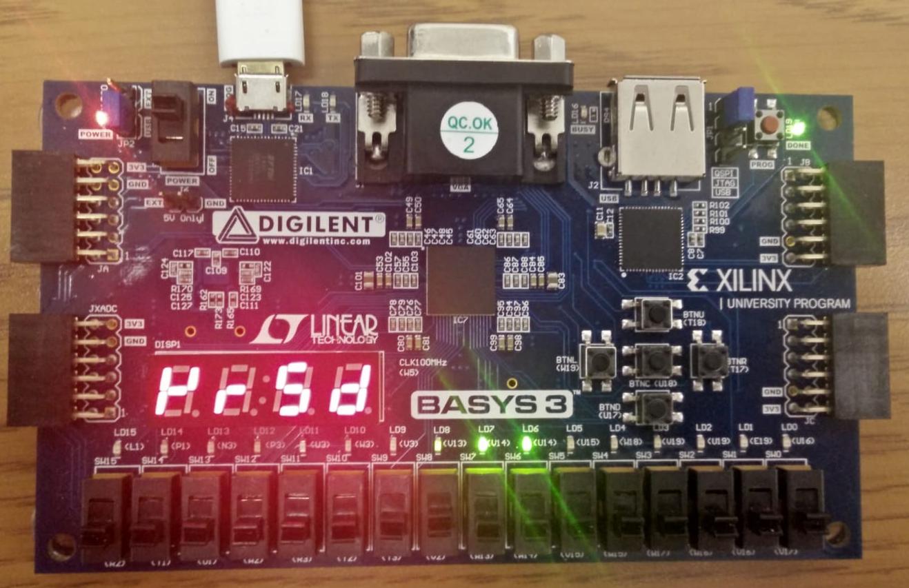
Figure 17 presents a toy sample application written in MSP430 C. In it, is an 8-bit General Purpose Input Output (GPIO) port which, in the synthesized HW, is connected to LEDs 0-7 of Basys3 FPGA. Lines 2-4 allocate buffers for the attestation challenge and response and initialize the challenge buffer. In practice, the challenge is received from via communication channels such as MSP430 Universal Asynchronous Receiver/Transmitter (UART). For the sake of clarity and brevity we omit the communication step from the example and set the challenge to a constant. Line 6 in Figure 17 sets P3 GPIO as output (i.e., an actuator port) and line 7 initializes all 8 bits to zero, making all LEDs initially off. The main application loop starts at line 10; at every iteration an artificial delay of 3 million integer increments is introduced and then P3 output value is incremented. This results in a binary counter being displayed on the 8 LEDs. At every time the counter value reached a multiple of 10 (line 16), all LEDs turn on (line 18) and the procedure is called in line 19 (by default VRASED is computed in the entire program memory, but the range is configurable and allows for data memory attestation as well). The LEDs remain on until the end of computation. After completion of attestation, the attestation result is saved in the response buffer and the counter resumes. In practical applications, such result can be reported back to (via UART) as an authenticated measurement of the device’s state. A demo video of this application running on real hardware and computing in a small fraction of a second is available on VRASED’s repository [1].