Anisotropic and controllable Gilbert-Bloch dissipation in spin valves
Abstract
Spin valves form a key building block in a wide range of spintronic concepts and devices from magnetoresistive read heads to spin-transfer-torque oscillators. We elucidate the dependence of the magnetic damping in the free layer on the angle its equilibrium magnetization makes with that in the fixed layer. The spin pumping-mediated damping is anisotropic and tensorial, with Gilbert- and Bloch-like terms. Our investigation reveals a mechanism for tuning the free layer damping in-situ from negligible to a large value via the orientation of fixed layer magnetization, especially when the magnets are electrically insulating. Furthermore, we expect the Bloch contribution that emerges from the longitudinal spin accumulation in the non-magnetic spacer to play an important role in a wide range of other phenomena in spin valves.
Introduction. – The phenomenon of magnetoresistance is at the heart of contemporary data storage technologies Fert (2008); Parkin et al. (2003). The dependence of the resistance of a multilayered heterostructure comprising two or more magnets on the angles between their respective magnetizations has been exploited to read magnetic bits with a high spatial resolution Nagasaka (2009). Furthermore, spin valves comprised of two magnetic layers separated by a non-magnetic conductor have been exploited in magnetoresistive random access memories Åkerman (2005); Parkin et al. (2003); Bhatti et al. (2017). Typically, in such structures, one ‘free layer’ is much thinner than the other ‘fixed layer’ allowing for magnetization dynamics and switching in the former. The latter serves to spin-polarize the charge currents flowing across the device and thus exert spin-torques on the former Brataas et al. (2012); Berger (1996); Slonczewski (1996); Ralph and Stiles (2008). Such structures exhibit a wide range of phenomena from magnetic switching Bhatti et al. (2017) to oscillations Kim (2012); Silva and Rippard (2008) driven by applied electrical currents.
With the rapid progress in taming pure spin currents Bauer et al. (2012); Kruglyak et al. (2010); Uchida et al. (2010); Adachi et al. (2013); Chumak et al. (2015); Maekawa et al. (2012); Hirsch (1999); Saitoh et al. (2006); Weiler et al. (2013), magnetoresistive phenomena have found a new platform in hybrids involving magnetic insulators (MIs). The electrical resistance of a non-magnetic metal (N) was found to depend upon the magnetic configuration of an adjacent insulating magnet Nakayama et al. (2013); Huang et al. (2012); Althammer et al. (2013); Vlietstra et al. (2013). This phenomenon, dubbed spin Hall magnetoresistance (SMR), relies on the pure spin current generated via spin Hall effect (SHE) in N Chen et al. (2013, 2016). The SHE spin current accumulates spin at the MI/N interface, which is absorbed by the MI depending on the angle between its magnetization and the accumulated spin polarization. The net spin current absorbed by the MI manifests as additional magnetization-dependent contribution to resistance in N via the inverse SHE. The same principle of magnetization-dependent spin absorption by MI has also been exploited in demonstrating spin Nernst effect Meyer et al. (2017), i.e. thermally generated pure spin current, in platinum.
While the ideas presented above have largely been exploited in sensing magnetic fields and magnetizations, tunability of the system dissipation is a valuable, underexploited consequence of magnetoresistance. Such an electrically controllable resistance of a magnetic wire hosting a domain wall Parkin et al. (2008) has been suggested as a basic circuit element Wang et al. (2009) in a neuromorphic computing Mead (1990) architecture. In addition to the electrical resistance or dissipation, the spin valves should allow for controlling the magnetic damping in the constituent magnets Tserkovnyak et al. (2005). Such an in-situ control can be valuable in, for example, architectures where a magnet is desired to have a large damping to attain low switching times and a low dissipation for spin dynamics and transport Kruglyak et al. (2010); Chumak et al. (2015). Furthermore, a detailed understanding of magnetic damping in spin valves is crucial for their operation as spin-transfer-torque oscillators Kim (2012) and memory cells Bhatti et al. (2017).
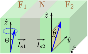
Inspired by these new discoveries Nakayama et al. (2013); Meyer et al. (2017) and previous related ideas Tserkovnyak et al. (2005, 2003); Taniguchi and Imamura (2007); Polishchuk et al. (2018), we suggest new ways of tuning the magnetic damping of the free layer in a spin valve (Fig. 1) via controllable absorption by the fixed layer of the spin accumulated in the spacer N due to spin pumping Tserkovnyak et al. (2002, 2005). The principle for this control over spin absorption is akin to the SMR effect discussed above and capitalizes on altering the magnetization direction. When spin relaxation in N is negligible, the spin lost by is equal to the spin absorbed by . This lost spin appears as tensorial Gilbert Gilbert (2004) and Bloch Bloch (1946) damping in magnetization dynamics. In its isotropic form, the Gilbert contribution arises due to spin pumping and is well established Berger (2001); Tserkovnyak et al. (2002, 2003, 2005); Mosendz et al. (2008); Taniguchi and Imamura (2007); Chiba et al. (2015). We reveal that the Bloch term results from backflow due to a finite dc longitudinal spin accumulation in N. Our results for the angular and tensorial dependence of the Gilbert damping are also, to best of our knowledge, new.
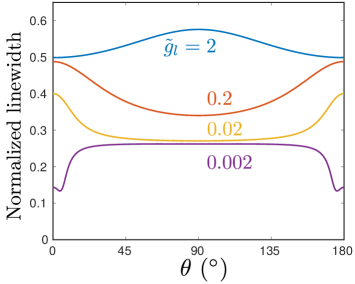
We show that the dissipation in , expressed in terms of ferromagnetic resonance (FMR) linewidth, varies with the angle between the two magnetizations (Fig. 3). The maximum dissipation is achieved in collinear or orthogonal configurations depending on the relative size of the spin-mixing and longitudinal spin conductances of the N subsystem. For very low , which can be achieved employing insulating magnets, the spin pumping mediated contribution to the linewidth vanishes for collinear configurations and attains a -independent value for a small non-collinearity. This can be used to strongly modulate the magnetic dissipation in electrically via, for example, an comprised by a magnetoelectric material Fusil et al. (2014).
FMR linewidth. – Disregarding intrinsic damping for convenience, the magnetization dynamics of including a dissipative spin transfer torque arising from the spin current lost may be expressed as:
| (1) |
Here, is the unit vector along the magnetization treated within the macrospin approximation, is the gyromagnetic ratio, is the saturation magnetization, is the volume of , and is the effective magnetic field. Under certain assumptions of linearity as will be detailed later, Eq, (1) reduces to the Landau-Lifshitz equation with Gilbert-Bloch damping Gilbert (2004); Bloch (1946):
| (2) |
Considering the equilibrium orientation , Eq. (2) is restricted to the small transverse dynamics described by , while the z-component is fully determined by the constraint . Parameterized by a diagonal dimensionless tensor , the Gilbert damping has been incorporated via in Eq. (2). The Bloch damping is parametrized via a diagonal frequency tensor as . A more familiar, although insufficient for the present considerations, form of Bloch damping can be obtained by assuming isotropy in the transverse plane: . This form, restricted to transverse dynamics, makes its effect as a relaxation mechanism with characteristic time evident. The Bloch damping, in general, captures the so-called inhomogeneous broadening and other, frequency independent contributions to the magnetic damping.
Considering uniaxial easy-axis and easy-plane anisotropies, parametrized respectively by and 111The easy-plane may stem from the shape anisotropy in thin films, in which case while the easy-axis may be magnetocrystalline in nature Akhiezer et al. (1968)., the magnetic free energy density is expressed as: with as the applied static plus microwave field. Employing the effective field in Eq. (2) and switching to Fourier space [], we obtain the resonance frequency . Here, and . The FMR linewidth is evaluated as:
| (3) |
where is the frequency of the applied microwave field and is approximately close to resonance, and for a weak easy-plane anisotropy. Thus, in addition to the anisotropic Gilbert contributions, the Bloch damping provides a nearly frequency-independent offset in the linewidth.
Spin flow. – We now examine spin transport in the device with the aim of obtaining the damping parameters that determine the linewidth [Eq. (Anisotropic and controllable Gilbert-Bloch dissipation in spin valves)]. The N layer is considered thick enough to eliminate static exchange interaction between the two magnetic layers Tserkovnyak et al. (2005); Chiba et al. (2015). Furthermore, we neglect the imaginary part of the spin-mixing conductance, which is small in metallic systems and does not affect dissipation in any case. Disregarding longitudinal spin transport and relaxation in the thin free layer, the net spin current lost by is the difference between the spin pumping and backflow currents Tserkovnyak et al. (2005):
| (4) |
where is the real part of the N interfacial spin-mixing conductance, and is the spatially homogeneous spin accumulation in the thin N layer. The spin current absorbed by may be expressed as Tserkovnyak et al. (2005):
| (5) |
where and are respectively the longitudinal spin conductance and the real part of the interfacial spin-mixing conductance of the N subsystem, denotes the unit vector along magnetization, and are the components of the resulting total spin conductance tensor. quantifies the absorption of the spin current along the direction of , the so-called longitudinal spin current. For metallic magnets, it is dominated by the diffusive spin current carried by the itinerant electrons, which is dissipated over the spin relaxation length Tserkovnyak et al. (2005). On the other hand, for insulating magnets, the longitudinal spin absorption is dominated by magnons Cornelissen et al. (2015); Goennenwein et al. (2015) and is typically much smaller than for the metallic case, especially at low temperatures. Considering (Fig. 1), Eq. (Anisotropic and controllable Gilbert-Bloch dissipation in spin valves) yields , , , , and .
Relegating the consideration of a small but finite spin relaxation in the thin N layer to the supplemental material Sup , we assume here that the spin current lost by is absorbed by , i.e., . Imposing this spin current conservation condition, the spin accumulation in N along with the currents themselves can be determined. We are primarily interested in the transverse (x and y) components of the spin current since these fully determine the magnetization dynamics ():
| (6) | ||||
where and . The spin lost by appears as damping in the magnetization dynamics [Eqs. (1) and (2)] Tserkovnyak et al. (2002, 2005).
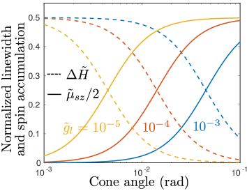
We pause to comment on the behavior of thus obtained [Eq. (6)]. Typically, is considered to be first or second order in the cone angle, and thus negligibly small. However, as discussed below, an essential new finding is that it becomes independent of the cone angle and large under certain conditions. For a collinear configuration and vanishing , results in Berger (2001). Its finite dc value contributes to the Bloch damping [Eq. (6)] Berger (2001). For a non-collinear configuration, and contributes to Gilbert damping via [Eq. (6)]. Thus, in general, we may express the spin accumulation as 222As detailed in the supplemental material Sup , we have disregarded the term in which oscillates with a frequency . Strictly speaking, this term needs to be included even in our linear analysis, since it produces terms oscillating with when multiplied with another term at . However, such a contribution is only relevant in a narrow parameter range which may be hard to resolve in an experiment. Furthermore, it requires a non-linear solution to the equations and is beyond the scope of the present work., where is the dc value and is the linear oscillating component. and contribute, respectively, to Bloch and Gilbert damping.
Gilbert-Bloch dissipation. – Equations (1) and (6) completely determine the magnetic damping in . However, these equations are non-linear and cannot be captured within our linearized framework [Eqs. (2) and (Anisotropic and controllable Gilbert-Bloch dissipation in spin valves)]. The leading order effects, however, are linear in all but a narrow range of parameters. Evaluating these leading order terms within reasonable approximations detailed in the supplemental material Sup , we are able to obtain the Gilbert and Bloch damping tensors and . Obtaining the general result numerically Sup , we present the analytic expressions for two cases covering a large range of the parameter space below.
First, we consider the collinear configurations in the limit of . As discussed above, we obtain and [Eq. (6)]. Thus the components of the damping tensors can be directly read from Eq. (6) as and . Here, we defined and is the Gilbert constant for the case of spin-pumping into an ideal spin sink Tserkovnyak et al. (2002, 2005). Substituting these values in Eq. (Anisotropic and controllable Gilbert-Bloch dissipation in spin valves), we find that the linewidth, or equivalently damping, vanishes. This is understandable since the system we have considered is not able to relax the z component of the spin at all. There can, thus, be no net contribution to magnetic damping. accumulated in N opposes the Gilbert relaxation via a negative Bloch contribution Berger (2001). The latter may also be understood as an anti-damping spin transfer torque due to the accumulated spin Brataas et al. (2012).
Next, we assume the system to be in a non-collinear configuration such that and may be disregarded, while simplifies to:
| (7) |
where and as above. This in turn yields the following Gilbert parameters via Eq. (6), with the Bloch tensor vanishing on account of :
| (8) |
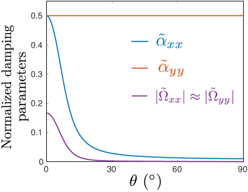
where as above. Thus, is -independent since lies in the y-z plane and the x-component of spin, the absorption of which is captured by , is always orthogonal to . , on the other hand, strongly varies with and is generally not equal to highlighting the tensorial nature of the Gilbert damping.
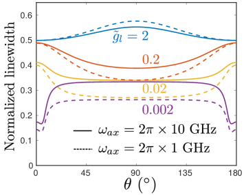
Figure 2 depicts the configurational dependence of normalized damping parameters. The Bloch parameters are appreciable only close to the collinear configurations on account of their proportionality to . The range over which they decrease to zero is proportional to the cone angle [Eq. (6)]. The Gilbert parameters are described sufficiently accurately by Eq. (8). The linewidth [Eq. (Anisotropic and controllable Gilbert-Bloch dissipation in spin valves)] normalized to its value for the case of spin pumping into a perfect spin sink has been plotted in Fig. 3. For low , the Bloch contribution partially cancels the Gilbert dissipation, which results in a smaller linewidth close to the collinear configurations Berger (2001). As increases, the relevance of Bloch contribution and diminishes, and the results approach the limiting condition described analytically by Eq. (8). In this regime, the linewidth dependence exhibits a maximum for either collinear or orthogonal configuration depending on whether is smaller or larger than unity. Physically, this change in the angle with maximum linewidth is understood to reflect whether transverse or longitudinal spin absorption is stronger.
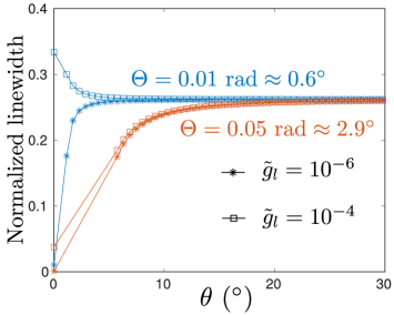
We focus now on the case of very low which can be realized in structures with electrically-insulating magnets. Figure 4 depicts the linewidth dependence close to the collinear configurations. The evaluated points are marked with stars and squares while the lines smoothly connect the calculated points. The gap in data for very small angles reflects the limited validity of our linear theory, as discussed in the supplemental material Sup . As per the limiting case discussed above, the linewidth should vanish in perfectly collinear states. A more precise statement for the validity of this limit is reflected in Fig. 4 and Eq. (6) as . For sufficiently low , the linewidth changes sharply from a negligible value to a large value over a range approximately equal to the cone angle . This shows that systems comprised of magnetic insulators bearing a very low are highly tunable as regards magnetic/spin damping by relatively small deviation from the collinear configuration. The latter may be accomplished electrically by employing magnetoelectric material Fusil et al. (2014) for or via current driven spin transfer torques Sinova et al. (2015); Ralph and Stiles (2008); Brataas et al. (2012).
Discussion. – Our identification of damping contributions as Gilbert-like and Bloch-like [Eq. (6)] treats as an independent variable that may result from SHE, for example. When it is caused by spin pumping current and , this Gilbert-Bloch distinction is less clear and becomes a matter of preference. Our results demonstrate the possibility of tuning the magnetic damping in an active magnet via the magnetization of a passive magnetic layer, especially for insulating magnets. In addition to controlling the dynamics of the uniform mode, this magnetic ‘gate’ concept Cornelissen et al. (2018) can further be employed for modulating the magnon-mediated spin transport in a magnetic insulator Cornelissen et al. (2015); Goennenwein et al. (2015). The anisotropy in the resulting Gilbert damping may also offer a pathway towards dissipative squeezing Kronwald et al. (2014) of magnetic modes, complementary to the internal anisotropy-mediated ‘reactive’ squeezing Kamra and Belzig (2016); Kamra et al. (2017). We also found the longitudinal accumulated spin, which is often disregarded, to significantly affect the dynamics. This contribution is expected to play an important role in a wide range of other phenomena such as spin valve oscillators.
Summary. – We have investigated the angular modulation of the magnetic damping in a free layer via control of the static magnetization in the fixed layer of a spin valve device. The damping can be engineered to become larger for either collinear or orthogonal configuration by choosing the longitudinal spin conductance of the fixed layer smaller or larger than its spin-mixing conductance, respectively. The control over damping is predicted to be sharp for spin valves made from insulating magnets. Our results pave the way for exploiting magneto-damping effects in spin valves.
Acknowledgments. – We acknowledge financial support from the Research Council of Norway through its Centers of Excellence funding scheme, project 262633, “QuSpin”, and from the Swedish Research Council, project 2018-03526, and Stiftelse Olle Engkvist Byggmästare.
References
- Fert (2008) Albert Fert, “Nobel lecture: Origin, development, and future of spintronics,” Rev. Mod. Phys. 80, 1517–1530 (2008).
- Parkin et al. (2003) S. Parkin, Xin Jiang, C. Kaiser, A. Panchula, K. Roche, and M. Samant, “Magnetically engineered spintronic sensors and memory,” Proceedings of the IEEE 91, 661–680 (2003).
- Nagasaka (2009) Keiichi Nagasaka, “Cpp-gmr technology for magnetic read heads of future high-density recording systems,” Journal of Magnetism and Magnetic Materials 321, 508 – 511 (2009), current Perspectives: Perpendicular Recording.
- Åkerman (2005) Johan Åkerman, “Toward a universal memory,” Science 308, 508–510 (2005), http://science.sciencemag.org/content/308/5721/508.full.pdf .
- Bhatti et al. (2017) Sabpreet Bhatti, Rachid Sbiaa, Atsufumi Hirohata, Hideo Ohno, Shunsuke Fukami, and S.N. Piramanayagam, “Spintronics based random access memory: a review,” Materials Today 20, 530 – 548 (2017).
- Brataas et al. (2012) Arne Brataas, Andrew D. Kent, and Hideo Ohno, “Current-induced torques in magnetic materials,” Nat Mat 11, 372–381 (2012).
- Berger (1996) L. Berger, “Emission of spin waves by a magnetic multilayer traversed by a current,” Phys. Rev. B 54, 9353–9358 (1996).
- Slonczewski (1996) J.C. Slonczewski, “Current-driven excitation of magnetic multilayers,” Journal of Magnetism and Magnetic Materials 159, L1 – L7 (1996).
- Ralph and Stiles (2008) D.C. Ralph and M.D. Stiles, “Spin transfer torques,” Journal of Magnetism and Magnetic Materials 320, 1190 – 1216 (2008).
- Kim (2012) Joo-Von Kim, “Chapter four - spin-torque oscillators,” (Academic Press, 2012) pp. 217 – 294.
- Silva and Rippard (2008) T.J. Silva and W.H. Rippard, “Developments in nano-oscillators based upon spin-transfer point-contact devices,” Journal of Magnetism and Magnetic Materials 320, 1260 – 1271 (2008).
- Bauer et al. (2012) Gerrit E. W. Bauer, Eiji Saitoh, and Bart J. van Wees, “Spin caloritronics,” Nat Mater 11, 391 (2012).
- Kruglyak et al. (2010) V V Kruglyak, S O Demokritov, and D Grundler, “Magnonics,” Journal of Physics D: Applied Physics 43, 264001 (2010).
- Uchida et al. (2010) K. Uchida, J. Xiao, H. Adachi, J. Ohe, S. Takahashi, J. Ieda, T. Ota, Y. Kajiwara, H. Umezawa, H. Kawai, G. E. W. Bauer, S. Maekawa, and E. Saitoh, “Spin seebeck insulator,” Nat Mater 9, 894–897 (2010).
- Adachi et al. (2013) Hiroto Adachi, Ken ichi Uchida, Eiji Saitoh, and Sadamichi Maekawa, “Theory of the spin seebeck effect,” Reports on Progress in Physics 76, 036501 (2013).
- Chumak et al. (2015) A. V. Chumak, V. I. Vasyuchka, A. A. Serga, and B. Hillebrands, “Magnon spintronics,” Nat Phys 11, 453 (2015).
- Maekawa et al. (2012) S. Maekawa, S.O. Valenzuela, E. Saitoh, and T. Kimura, Spin Current, Series on Semiconductor Science and Technology (OUP Oxford, 2012).
- Hirsch (1999) J. E. Hirsch, “Spin hall effect,” Phys. Rev. Lett. 83, 1834–1837 (1999).
- Saitoh et al. (2006) E. Saitoh, M. Ueda, H. Miyajima, and G. Tatara, “Conversion of spin current into charge current at room temperature: Inverse spin-hall effect,” Applied Physics Letters 88, 182509 (2006), https://doi.org/10.1063/1.2199473 .
- Weiler et al. (2013) Mathias Weiler, Matthias Althammer, Michael Schreier, Johannes Lotze, Matthias Pernpeintner, Sibylle Meyer, Hans Huebl, Rudolf Gross, Akashdeep Kamra, Jiang Xiao, Yan-Ting Chen, HuJun Jiao, Gerrit E. W. Bauer, and Sebastian T. B. Goennenwein, “Experimental test of the spin mixing interface conductivity concept,” Phys. Rev. Lett. 111, 176601 (2013).
- Nakayama et al. (2013) H. Nakayama, M. Althammer, Y.-T. Chen, K. Uchida, Y. Kajiwara, D. Kikuchi, T. Ohtani, S. Geprägs, M. Opel, S. Takahashi, R. Gross, G. E. W. Bauer, S. T. B. Goennenwein, and E. Saitoh, “Spin hall magnetoresistance induced by a nonequilibrium proximity effect,” Phys. Rev. Lett. 110, 206601 (2013).
- Huang et al. (2012) S. Y. Huang, X. Fan, D. Qu, Y. P. Chen, W. G. Wang, J. Wu, T. Y. Chen, J. Q. Xiao, and C. L. Chien, “Transport magnetic proximity effects in platinum,” Phys. Rev. Lett. 109, 107204 (2012).
- Althammer et al. (2013) Matthias Althammer, Sibylle Meyer, Hiroyasu Nakayama, Michael Schreier, Stephan Altmannshofer, Mathias Weiler, Hans Huebl, Stephan Geprägs, Matthias Opel, Rudolf Gross, Daniel Meier, Christoph Klewe, Timo Kuschel, Jan-Michael Schmalhorst, Günter Reiss, Liming Shen, Arunava Gupta, Yan-Ting Chen, Gerrit E. W. Bauer, Eiji Saitoh, and Sebastian T. B. Goennenwein, “Quantitative study of the spin hall magnetoresistance in ferromagnetic insulator/normal metal hybrids,” Phys. Rev. B 87, 224401 (2013).
- Vlietstra et al. (2013) N. Vlietstra, J. Shan, V. Castel, B. J. van Wees, and J. Ben Youssef, “Spin-hall magnetoresistance in platinum on yttrium iron garnet: Dependence on platinum thickness and in-plane/out-of-plane magnetization,” Phys. Rev. B 87, 184421 (2013).
- Chen et al. (2013) Yan-Ting Chen, Saburo Takahashi, Hiroyasu Nakayama, Matthias Althammer, Sebastian T. B. Goennenwein, Eiji Saitoh, and Gerrit E. W. Bauer, “Theory of spin hall magnetoresistance,” Phys. Rev. B 87, 144411 (2013).
- Chen et al. (2016) Yan-Ting Chen, Saburo Takahashi, Hiroyasu Nakayama, Matthias Althammer, Sebastian T B Goennenwein, Eiji Saitoh, and Gerrit E W Bauer, “Theory of spin hall magnetoresistance (smr) and related phenomena,” Journal of Physics: Condensed Matter 28, 103004 (2016).
- Meyer et al. (2017) S. Meyer, Y.-T. Chen, S. Wimmer, M. Althammer, T. Wimmer, R. Schlitz, S. Geprägs, H. Huebl, D. Ködderitzsch, H. Ebert, G. E. W. Bauer, R. Gross, and S. T. B. Goennenwein, “Observation of the spin nernst effect,” Nature Materials 16, 977 (2017).
- Parkin et al. (2008) Stuart S. P. Parkin, Masamitsu Hayashi, and Luc Thomas, “Magnetic domain-wall racetrack memory,” Science 320, 190–194 (2008).
- Wang et al. (2009) X. Wang, Y. Chen, H. Xi, H. Li, and D. Dimitrov, “Spintronic memristor through spin-torque-induced magnetization motion,” IEEE Electron Device Letters 30, 294–297 (2009).
- Mead (1990) C. Mead, “Neuromorphic electronic systems,” Proceedings of the IEEE 78, 1629–1636 (1990).
- Tserkovnyak et al. (2005) Yaroslav Tserkovnyak, Arne Brataas, Gerrit E. W. Bauer, and Bertrand I. Halperin, “Nonlocal magnetization dynamics in ferromagnetic heterostructures,” Rev. Mod. Phys. 77, 1375–1421 (2005).
- Tserkovnyak et al. (2003) Yaroslav Tserkovnyak, Arne Brataas, and Gerrit E. W. Bauer, “Dynamic stiffness of spin valves,” Phys. Rev. B 67, 140404 (2003).
- Taniguchi and Imamura (2007) Tomohiro Taniguchi and Hiroshi Imamura, “Enhancement of the gilbert damping constant due to spin pumping in noncollinear ferromagnet/nonmagnet/ferromagnet trilayer systems,” Phys. Rev. B 76, 092402 (2007).
- Polishchuk et al. (2018) D. M. Polishchuk, T. I. Polek, A. Kamra, A. F. Kravets, A. I. Tovstolytkin, A. Brataas, and V. Korenivski, “Spin relaxation in multilayers with synthetic ferrimagnets,” Phys. Rev. B 98, 144401 (2018).
- Tserkovnyak et al. (2002) Yaroslav Tserkovnyak, Arne Brataas, and Gerrit E. W. Bauer, “Enhanced gilbert damping in thin ferromagnetic films,” Phys. Rev. Lett. 88, 117601 (2002).
- Gilbert (2004) T. L. Gilbert, “A phenomenological theory of damping in ferromagnetic materials,” IEEE Transactions on Magnetics 40, 3443–3449 (2004).
- Bloch (1946) F. Bloch, “Nuclear induction,” Phys. Rev. 70, 460–474 (1946).
- Berger (2001) L. Berger, “Effect of interfaces on gilbert damping and ferromagnetic resonance linewidth in magnetic multilayers,” Journal of Applied Physics 90, 4632–4638 (2001).
- Mosendz et al. (2008) O. Mosendz, B. Kardasz, and B. Heinrich, “Ferromagnetic resonance and spin momentum exchange in crystalline magnetic ultrathin films in noncollinear configuration,” Journal of Applied Physics 103, 07B505 (2008).
- Chiba et al. (2015) Takahiro Chiba, Gerrit E. W. Bauer, and Saburo Takahashi, “Magnetization damping in noncollinear spin valves with antiferromagnetic interlayer couplings,” Phys. Rev. B 92, 054407 (2015).
- Fusil et al. (2014) S. Fusil, V. Garcia, A. Barthélémy, and M. Bibes, “Magnetoelectric devices for spintronics,” Annual Review of Materials Research 44, 91–116 (2014).
- Note (1) The easy-plane may stem from the shape anisotropy in thin films, in which case while the easy-axis may be magnetocrystalline in nature Akhiezer et al. (1968).
- Cornelissen et al. (2015) L. J. Cornelissen, J. Liu, R. A. Duine, J. Ben Youssef, and B. J. van Wees, “Long-distance transport of magnon spin information in a magnetic insulator at room temperature,” Nature Physics 11, 1022 (2015).
- Goennenwein et al. (2015) Sebastian T. B. Goennenwein, Richard Schlitz, Matthias Pernpeintner, Kathrin Ganzhorn, Matthias Althammer, Rudolf Gross, and Hans Huebl, “Non-local magnetoresistance in yig/pt nanostructures,” Applied Physics Letters 107, 172405 (2015), http://dx.doi.org/10.1063/1.4935074 .
- (45) See supplemental material for a discussion on the case of collinear configurations with small , details on the numerical analysis with related approximations, dependence of the FMR linewidth on the easy-plane anisotropy and spin-mixing conductance , and the effect of finite spin relaxation in the spacer layer.
- Note (2) As detailed in the supplemental material Sup , we have disregarded the term in which oscillates with a frequency . Strictly speaking, this term needs to be included even in our linear analysis, since it produces terms oscillating with when multiplied with another term at . However, such a contribution is only relevant in a narrow parameter range which may be hard to resolve in an experiment. Furthermore, it requires a non-linear solution to the equations and is beyond the scope of the present work.
- Sinova et al. (2015) Jairo Sinova, Sergio O. Valenzuela, J. Wunderlich, C. H. Back, and T. Jungwirth, “Spin hall effects,” Rev. Mod. Phys. 87, 1213–1260 (2015).
- Cornelissen et al. (2018) L. J. Cornelissen, J. Liu, B. J. van Wees, and R. A. Duine, “Spin-current-controlled modulation of the magnon spin conductance in a three-terminal magnon transistor,” Phys. Rev. Lett. 120, 097702 (2018).
- Kronwald et al. (2014) Andreas Kronwald, Florian Marquardt, and Aashish A Clerk, “Dissipative optomechanical squeezing of light,” New Journal of Physics 16, 063058 (2014).
- Kamra and Belzig (2016) Akashdeep Kamra and Wolfgang Belzig, “Super-poissonian shot noise of squeezed-magnon mediated spin transport,” Phys. Rev. Lett. 116, 146601 (2016).
- Kamra et al. (2017) Akashdeep Kamra, Utkarsh Agrawal, and Wolfgang Belzig, “Noninteger-spin magnonic excitations in untextured magnets,” Phys. Rev. B 96, 020411 (2017).
- Akhiezer et al. (1968) A.I. Akhiezer, V.G. Bar’iakhtar, and S.V. Peletminski, Spin waves (North-Holland Publishing Company, Amsterdam, 1968).
Supplemental material with the manuscript Anisotropic and controllable Gilbert-Bloch dissipation in spin valves by
Akashdeep Kamra, Dmytro M. Polishchuk, Vladislav Korenivski and Arne Brataas
I Collinear configuration without longitudinal spin relaxation
In order to appreciate some of the subtleties, we first examine the collinear configuration in the limit of vanishing longitudinal spin conductance. and imply the following values for the various parameters:
| (S1) |
whence we obtain:
| (S2) | ||||
| (S3) |
where we have assumed magnetization dynamics as given by the Landau-Lifshitz equation without damping, and the phase of is treated as the reference and set to zero. In order to obtain analytic expressions, we make the assumption such that we have:
| (S4) | ||||
| (S5) | ||||
| (S6) |
In contrast with our assumptions in the main text, a term oscillating with appears. Furthermore, it yields contributions to the Bloch damping via products such as , which now have contributions oscillating at due to the as well as . We obtain:
| (S7) | ||||
| (S8) |
substituting which into Eq. (3) from the main text yields a vanishing linewidth and damping. This is expected from the general spin conservation argument that there can be no damping in the system if it is not able to dissipate the z-component of the spin. In fact, in the above considerations, contributed with the opposite sign to and , and thus dropped out of the linewidth altogether. This also justifies our ignoring this contribution in the main text.
II Numerical evaluation
Despite the additional complexity in the previous section, we could treat the dynamics within our linearized framework. However, in the general case, has contributions at all multiples of and cannot be evaluated in a simple manner. A general non-linear analysis must be employed which entails treating the magnetization dynamics numerically altogether. Such an approach prevents us from any analytic description of the system, buries the underlying physics, and is thus undesirable.
Fortunately, the effects of non-linear terms are small for all, but a narrow, range of parameters. Hence, we make some simplifying assumptions here and continue treating our system within the linearized theory. We only show results in the parameter range where our linear analysis is adequate. Below, we describe the numerical routine for evaluating the various quantities. To be begin with the average cone angle is defined as:
| (S9) |
where denotes averaging over time. The spin accumulation is expressed as with:
| (S10) | ||||
| (S11) |
The above expressions combined with the equations for the spin current flow (Eqs. (6) in the main text) directly yield the Gilbert and Bloch damping tensors.
III Variation with additional parameters
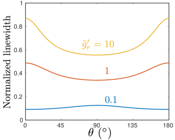
Here, we discuss the dependence of the FMR linewidth on the easy-plane anisotropy and the spin-mixing conductance of the N interface. The results are plotted in Fig. 2. A high easy-plane anisotropy is seen to diminish the configuration dependence of the linewidth and is thus detrimental to the dissipation tunability. The easy-axis anisotropy, on the other hand, is absorbed in and does not need to be examined separately. We also see an increase in the configuration dependence of the damping with an increasing . This is understood simply as an increased damping when the spin is absorbed more efficiently due to a larger . The damping is expected to reach the case of spin pumping into a perfect spin sink in the limit of and .
IV Effect of spin relaxation in the spacer layer
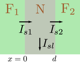
We now address the role of the small but finite spin relaxation in the non-magnetic spacer layer. To this end, we consider that a part of the spin current injected into N by is lost as the “spin-leakage current” , as depicted in Fig. 3, such that . In order to evaluate the leakage, we consider the spin diffusion equation in N which reads Tserkovnyak et al. (2005):
| (S12) |
where and are diffusion constant and spin-flip time, respectively. We now integrate the equation over the thickness of N:
| (S13) |
Since the N-layer thickness is typically much smaller than the spin diffusion length in N (e.g., a few nm versus a few hundred nm for Cu), we treat on the right hand side as a constant. Furthermore, in simplifying the left hand side, we invoke the expression for the spin current Tserkovnyak et al. (2005): , with the one-spin density of states per unit volume and the interfacial area. Thus, we obtain
| (S14) |
which simplifies to the desired relation with
| (S15) |
where is the volume of the spacer layer N.
It is easy to see that accounting for spin leakage, as derived in Eq. (S15), results in the following replacements to Eqs. (6) of the main text:
| (S16) |
Since all our specific results are based on Eqs. (6) of the main text, this completes our assessment of the role played by spin relaxation in N. Physically, this new result means that the condition for no spin relaxation in the system, which was previously treated as , is now amended to . This, however, does not affect the generality and significance of the key results presented in the main text.