Nm-sized cryogenic hydrogen clusters for a laser-driven proton source
Abstract
A continuous cryogenic hydrogen cluster-jet target has been developed for laser-plasma interaction studies, in particular as a source for the acceleration of protons. Major advantages of the cluster-jet target are the compatibility with pulsed high repetition lasers and the absence of debris. The cluster-jet target was characterized using the Mie-scattering technique allowing to determine the cluster size and to compare it with an empirical prediction. In addition, an estimation of the cluster beam density was performed. The system was implemented at the high power laser system ARCTURUS and first successful measurements show the acceleration of protons after irradiation by high intensity laser pulses with a repetition rate of five Hertz.
pacs:
42.25.Fx, 36.40.-c, 52.38.-rI Introduction
In the field of laser-induced ion acceleration, stability and applicability have tremendously increased over the last two decades. Starting from the process of target-normal-sheath acceleration Wilks et al. (2001); Mora (2003) using flat metal foil targets, nowadays, a variety of different acceleration schemes have been identified. In the route of improving the parameters of laser-driven proton beams including flux, energy distribution, and collimation, new acceleration regimes have been proposed, like radiation-pressure-acceleration (RPA) Henig et al. (2009); Yan et al. (2008); Aurand et al. (2013a) or break-out-afterburner (BOA) and more sophisticated targets have been proposed Aurand et al. (2013b, 2014). A detailed review on the recent progress achieved in the area of laser-ion acceleration can be found in the publications of A. Macchi Macchi, Borghesi, and Passoni (2013); Macchi (2017).
Two major disadvantages of most targets are the fact that they are made for single use, meaning they need to be replaced after each laser shot and that a large part of the incident laser energy is lost by the escape of energetic electrons transversely to the laser propagation direction Tresca et al. (2011); Prencipe et al. (2017).
Ideas to overcome the first problem are for example the use of a gas target, as described by M. Helle Helle et al. (2016). The drawback is the low mass density resulting in a low particle flux. Other ideas are the use of a liquid or solid, dispersed in a jet-like structure Karsch et al. (2003); Schnurer et al. (2005). This guarantees an unlimited amount of target material at solid-state density but comes with the difficulty of proper laser alignment onto the often very fine structure. The second problem, the energy loss by escaping electrons, could be overcome by so-called mass-limited targets, e.g. using a very fine support structure or fully levitating targets Hilz et al. (2018). Those targets face again the problem of replacement after each laser shot.
In contrast, a cluster-jet target overcomes most of the difficulties mentioned above. The cluster source delivers on the one hand mass-limited targets in a continuous beam, since every cluster serves as an isolated target. On the other hand, the cluster density is high enough to have a sufficient number of clusters in the focal volume during the interaction, which guarantees a high shot-to-shot stability. The clusters can be produced from a liquid Prasad et al. (2012) or cryogenic cooled gas Jinno et al. (2017).
A major benefit in the use of hydrogen gas is the high purity of the source allowing only protons to be accelerated in contrast to most other targets containing hydrocarbons where also heavier ions can be accelerated.
Recently, the use of micrometer-sized clusters of hydrogen for proton acceleration were demonstrated by Jinno et al. Jinno et al. (2018). Presented in this publication are the development and first successful measurements using a novel cluster-jet target for laser-driven proton acceleration, aiming for a reliable, high repetition rate with low maintenance for future applications. After implementation, the characterization of the target parameters such as cluster size using the technique of Mie-scattering has been performed. The performance of the target by irradiation with a laser beam at an intensity of =1020 W/cm2 has been successfully demonstrated and protons in the keV range were observed.
II The cluster-jet target
The cluster-jet target MCT1S was designed and built by the University of Münster to perform detailed studies on the production of cluster-jet beams. In a first set of measurements, a hydrogen cluster beam was well defined by a set of skimmers and studied of up to behind the target beam generator Täschner (2012). Recently, the cluster-jet target MCT1S was revised and optimized in order to perform detailed investigations on the cluster-laser interaction very close to the target generator and at high target thicknesses, i.e. Grieser (2014, 2018). Depending on the experimental setup, this cluster-jet target offers the possibility to cool down gaseous target materials to temperatures of roughly . For the experiments presented here the target was modified to allow for interaction studies directly behind the nozzle, which increased the lowest temperature to roughly . The (pre-cooled) gas is directed with pressures of e.g. through a fine Laval nozzle with typical diameters of . With a starting temperature well below the inversion temperature and due to the specific convergent-divergent shape of the nozzle, the gas is further cooled down during passing the nozzle due to adiabatic cooling and the formation of clusters develops.
The Laval nozzle is one main component of a cluster-jet target and its complex inner geometry is essential for the cluster production process. The convergent short inlet cone merges after the narrowest point of the nozzle in a long divergent outlet zone with first a constant opening angle followed by a radius (cf. Fig. 1). The nozzles used here originate from a nozzle production line of CERN (Conseil européen pour la recherche nucléaire). Based on this production process, an improved production process was developed at the University of Münster to ensure the availability and the diversity of Laval nozzles for upcoming experiments using a cluster-jet target with different gases and stagnation conditions.

The cluster-jet target can be used with different gases as target material. Depending on the used target material, the nozzle geometry has to be adapted in order to provide appropriate target thicknesses and gas flows through the nozzle for the different gases. Thereby, the general geometry of the nozzle was the same and only the narrowest inner diameter has to been varied. In case of hydrogen, the nozzle had an inner diameter of .
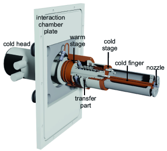
In order to offer the possibility to cool down the target gas before entering the nozzle to temperatures of about , required to increase the target density as well as the cluster size, a two-stage cold head is used (cf. Table 1). The applied cold head works with a closed helium cycle in combination with a compressor. Both parts are connected via flexible high pressure lines. A displacer inside the cold head separates two volumes. According to the Gifford-McMahon process the movement of the displacer leads to a compression and expansion of the helium within the volumes resulting in a heat exchange with the compressor. The first stage of the cold head, the warm stage, pre-cools the gas and the second stage, the cold stage, realizes the final low temperatures of the nozzle.
| target components | specification |
|---|---|
| cold head | Leybold RGD |
| compressor | Leybold Coolpak H |
| pressure controller | SLA (Brooks) |
| flow meter | SLA (Brooks) |
| hydrogen purifier | HP- (Johnson Matthey) |
| baratron | (MKS) |
| temperature control | Lakeshore / |
| PSP- (GwInstek) | |
| temperature diodes | 1. Stage: DT 670 (Lakeshore) |
| 2. Stage: DT 670 (Lakeshore) | |
| heating cartridges | 1. Stage: 50 W (Lakeshore) |
| 2. Stage: 100 W (Lakeshore) |
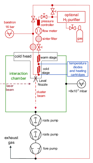
Before entering the cold head, the target gas is guided through a pressure controller, to monitor and control the pressure of the gas in front of the nozzle, and is then fed to a flow meter (see Fig. 4). The information of the flow meter is used to calculate the minimum diameter of the nozzle at a given pressure which offers the possibility to recognize a blocked nozzle. Due to the very small diameter of the nozzle of, e.g., for hydrogen, the gas is additionally purified using a palladium hydrogen purifier. Therefore, the hydrogen gas has a purity of directly behind the device. The target gas is directed through pipes wrapped around the two stages of the cold head (see Fig. 2). The pipes located at the cooling parts of the cold head are made out of copper to guarantee an optimal heat exchange between cold head and gas. The gas pipes in between the cooling parts are made of stainless steel to reduce a direct heat exchange between the cryogenic stages for an optimal cooling of the gas. Two additional sinter filters are installed to avoid a blocking of the nozzle due to possible impurities within the piping system of the target gas. Finally, the cooled gas enters a cold finger mounted directly on top of the cold stage of the cold head. The cold finger is used to place the nozzle exit and by this the interaction point between cluster and laser beam in the center of the interaction chamber. The cold finger consists of copper and is surrounded by a small walled hollow cylinder made out of reflecting stainless steel acting as heat radiation shielding. On the end of the cold finger, the Laval nozzle is mounted. Both, the cold finger as well as the nozzle are sealed with a circled indium sealing. This sealing is also gas tight at cryogenic temperatures and, therefore, ideally suited as nozzle sealing in the temperature range of importance here.
At the two stages of the cold head, temperature diodes and heating cartridges are installed to monitor and control the temperatures of both stages. The equipment of the cluster-jet target is remotely controlled by a slow control system realized in LabVIEW by National Instruments National Instruments (2018), which is also used to display the target parameters on a website and to store them every . With this system, it could be shown, that the stagnation conditions and consequently the characteristics of the cluster beam achieve a stability of better than and .
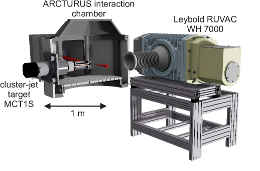
For the experiments presented here, the cluster-jet target is directly integrated in a removable interaction vacuum chamber plate and extends appropriately into the interaction chamber. For this reason, the laser pulse can be directly focused onto the cluster beam with no disturbing material like foils or walls in between. By this, the full laser performance is available and no disturbances occur. Moreover, if necessary, this setup allows for a fast and simple disassembly and installation of the cluster-jet target at the interaction chamber. Furthermore, even after removing and re-installation of the target, the position of the nozzle shows up exactly at the same position and no further re-adjustment of the laser focus with respect to the cluster beam is required.
The setup presented here allows for a very quick and simple change between different gases as target material. Depending on the gas, at maximum only the nozzle has to be exchanged and this can be done without dismounting the complete target. As a result, a series of measurements with various gas types can be performed rapidly one after the other.
Opposite to the cluster-jet target, a powerful roots pump is installed to directly pump away the cluster beam after the interaction with the laser beam to ensure a good vacuum in the interaction chamber (Fig. 3, Table 2). With this powerful pumping system the vacuum in the interaction chamber was below during the performed measurements at hydrogen gas flows of .
| vacuum pump | nominal pumping speed |
|---|---|
| Leybold SOGEVAC SV | |
| Leybold RUVAC WSU | |
| Leybold RUVAC WH |
III Cluster-jet characterization
In order to investigate the laser-cluster interaction and the underlying physical processes, it is necessary to determine the cluster beam characteristics. Of special interest is the target volume density at the position of the laser interaction point. Although a direct measurement in principle is possible, due to the experimental setup such a measurement would be accompanied here with large systematic uncertainties. Alternatively, a much more reliable method is an estimation using the gas flow through the nozzle. Since the gas flow meter information was designed for higher gas flows at lower temperatures the gas flow is calculated based on the well known stagnation conditions and the nozzle geometry. The gas volume flow through the nozzle can be calculated using Wutz, Adam, and Walcher (1988)
| (1) |
Therein, is the cross section of the narrowest point of the nozzle, and are the stagnation conditions of the gas in front of the nozzle, and are the normal pressure and temperature, is the molar mass of the gas, is the heat capacity ratio and is the universal gas constant. A calculation of the mass flow with respect to the gas flow
| (2) |
allows for a determination of the target volume density with the cluster beam cross section at the distance to the nozzle and the Avogadro constant
| (3) |
For the temperatures used, in good approximation the mean cluster velocity can be estimated assuming an ideal gas Täschner (2012)
| (4) |
In the case of a real gas the jet velocity might be lower by, e.g., a few percent. Therefore, the estimated target density might be larger by this number. Obviously the target density depends on the used gas and the stagnation conditions, which can easily be defined just by changing the nozzle temperature and/or the gas pressure. In good approximation the propagation of the cluster beam after leaving the nozzle is based on the intercept theorem Köhler (2015). Assuming a circular volume element of the cluster beam increases with increasing distance from the nozzle, results in a density decreases by with increasing distance . Taking this into account, the presented measurements were performed directly behind the nozzle at with respect to the nozzle exit. The estimated target densities for the presented measurements at the interaction point are listed in Table 3. The cluster beam diameter at the interaction point was calculated considering the opening angle of the nozzle of as cluster beam divergence. However, it has to be noted that previous measurements at much lower temperatures of, e.g., and with liquid hydrogen entering the nozzle allowed for an optical observation of the jet beam Köhler (2015). These studies resulted in a smaller divergence in the range of to Köhler (2015) resulting in higher target densities.
Next to the cluster beam density, the average number of atoms per cluster is an important key figure of clusters. It is predictable via the empirical Hagena’s scaling law Hagena (1992)
| (5) |
| (6) |
predicts the formation of clusters and a value of leads to an immense formation of clusters. Here, is a gas dependent constant Smith, Ditmire, and Tisch (1998), the narrowest inner nozzle diameter, and the expansion half angle of the nozzle.
The Hagena parameter and scaling law are based on measurements performed with nitrogen, carbon dioxide, and argon. Therefore, the equations hold true for these gas types. In case of hydrogen, mass distribution measurements were successfully performed at the University of Münster and resulted in a good agreement within an additional constant underestimation by a factor of Köhler (2015). Moreover, it was shown that the cluster mass distribution can be well described by a log-normal distribution
| (7) |
with the scaling parameters and , and the arithmetic mean
| (8) |
The diameter of a cluster can be calculated using the average number of atoms per cluster
| (9) |
The density of a cluster is assumed to be the solid density of the used gas and is the mass of the hydrogen atom. The estimated average cluster diameters for the measurements presented within this publication are shown and compared to measurements using Mie-scattering in Table 3.
IV Cluster size measurements using Mie-scattering
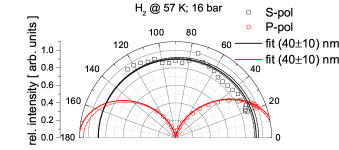
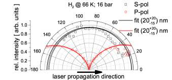
For further studies of the underlying proton-acceleration process and to compare with theoretical predictions described in section III an experimental verification of the cluster size was carried out. Mie-scattering Mie (1908) can be used for an accurate measurement of the cluster size. As illustrated in Fig. 5 a 3 W frequency-doubled solid state laser at 532 nm was used, focused to a spot size of about 50 m onto the cluster-jet 28 mm downstream from the Laval nozzle. In the following, the laser forward direction is defined as 0∘. Before entering the vacuum a /2 plate was installed to change the laser polarization direction. The cluster-jet was limited by a slit with a width of about 5 mm in the laser propagation direction to define a clear interaction volume. The scattered light was collected by an achromatic lens with a focal length of 75 mm and an acceptance angle of 23 mrad imaging the interaction point onto a glass fibre. This imaging line was placed on a rotatable stage and could be rotated between 20 ∘ and 130 ∘ in the laser incidence plane. The fibre was coupled onto a photomultiplier (PM - Hamamatsu R928) outside the vacuum chamber and the relative voltage was recorded as signal.
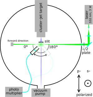
The angularly dependent scattering of the perpendicular- (S) or parallel- (P) polarized laser light, with respect to the detection plane, was measured. The intensity scattered by a single cluster, composed of atoms, into an angle , is given by Bohren and Huffman (1998)
| (10) |
where is the size parameter, which depends on the incident wavelength and the Mie-radius . is the distance between the detector and the interaction point, is the initial intensity and is a fitting parameter for the S- and P-polarized case, respectively. A change of the polarization of the incident laser light results in a different scattering behaviour. While perpendicular polarized light is scattered homogeneously, only having an asymmetric intensity in forward and backward direction, the parallel polarized light has an additional minimum at 90∘ with respect to the direction of the incident light.
Since there can be more than one cluster in the scattering volume, the total intensity scattered is given by the integral over all clusters consisting of atoms in the volume
| (11) |
Here, is the particle size distribution depending on the one hand on the spatial position within the cluster jet and on the other hand defined by the log-normal distribution of the statistical generation process of the clusters. The application of a 5 mm slit width directly behind the cluster nozzle leads to a decrease of the spatial distribution of the cluster-jet beam and by this to a well defined scattering volume. However, although principally possible, due to the limited covered scattering angle range and angular resolution, in this special case this method does not allow to resolve the log-normal particle size distribution. Based on that, the assumption was made, that the measured values are a reflection of the average size of the clusters. Following the theoretical approach described by C. F. Bohren Bohren and Huffman (1998), the theoretical Mie-scattering distributions for P- and S-polarized light were calculated and fitted to the measured values. Note that in the presented case the use of different polarizations instead of different wavelengths results Prasad et al. (2012) in a verification of the measurements. For the calculated values of the refractive index depending on the laser wavelength needs to be taken into account. For hydrogen =1.117 Johns and Wilhelm (1937) was assumed. Fig. 6 illustrates the measured values (symbols) and the theoretical fitted diameters (lines). The dashed lines represent the corresponding error range. A smaller scattering source results in a more spatially isotropic scatter behaviour. For this reason, the errors become large in this case. The results are summarized in Table 3. The predicted cluster diameters using the Hagena formula and the measured cluster diameters via the Mie-scattering setup are in good agreement within the uncertainties.
V Results of laser-driven acceleration using the hydrogen cluster-jet target
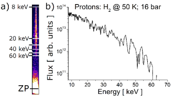
Preliminary measurements of proton acceleration using the hydrogen cluster-jet target at the ARCTURUS laser facility of the University of Düsseldorf were performed. A 200 TW Ti:Sapphire laser with an energy of 7 J before compression, a pulse duration of 30 fs and with a beam diameter of 80 mm was used to irradiate the cluster-jet beam. The laser pulse was focused by an f/2 off-axis parabola to a focal diameter of 4 m, corresponding to an intensity of 21020 W/cm2. For the results reported here, the hydrogen gas in front of the Laval nozzle had a temperature of roughly 50 K and a pressure of 16 bar resulting in a cluster size of roughly =45 nm.
The proton spectrum was measured along the laser forward direction by means of a Thompson-parabola spectrometer Gwynne et al. (2014). Figure 7a shows the raw image of proton track on the detector. In Fig. 7b the energy spectrum is presented which was extracted employing a MATHLAB routine. In this measurement, maximum energies of roughly 60 keV were observed. Moreover, a high shot-to-shot stability of the proton energy spectrum was demonstrated by subsequent shots and will be published elsewhere.
The calculated cluster target density in combination with the average number of atoms within one cluster predicted via the Hagena law allows for the estimation of the number of clusters within the focal volume (V=189 m3), defined as the volume within one Rayleigh-length of the laser focus. In the case of the proton-acceleration measurement the mean cluster number in the focal volume was determined to be . Consequently there is more than one single cluster located in the interaction volume which forms the basis for stable and reproducible proton spectra. These and other further results on the physics of the acceleration process, which is Coulomb-explosively driven, will be presented in detail in another publication.
| gas | pressure / bar | temperature / K | density / (atoms/cm3) | predicted cluster | measured cluster |
|---|---|---|---|---|---|
| diameter / nm | diameter / nm | ||||
| hydrogen | |||||
VI Conclusion
A cluster-jet target was designed, built and successfully taken into operation at the University of Münster. This target can be used with different gases and allows for a stable and continuous flow of pure target material. Additionally, this cluster-jet target was implemented at the ACTURUS laser facility of the University of Düsseldorf for laser-driven proton acceleration. A detailed technical description of the cluster source demonstrates the features and possibilities of such a target. Theoretical calculations of the essential cluster parameters, like density and cluster size using the Hagena relation for different stagnation conditions were performed. Moreover, the cluster sizes were measured using a Mie-scattering technique and the results demonstrate a good agreement with the Hagena prediction within the uncertainties. First successfully performed measurements using hydrogen clusters irradiated by a high-intensity 5 Hz laser prove the operational reliability of the target system by observing protons in the multi-keV range. Based on these results, a newly designed cluster-jet target is currently under construction at the University of Münster. This target will significantly extend the region of accessible stagnation conditions even towards the generation of hydrogen clusters from the liquid phase. This will result in significantly larger cluster sizes and higher densities to achieve considerable higher kinetic energies of the accelerated protons.
VII Acknowledgement
We acknowledge financial support by the German Federal Ministry of Education and Research (BMBF) joint research project No. 05K16PM3 and No. 05K16PFA. The work provided by the teams of the mechanical and electronic workshops at Münster University is very much appreciated and we thank them for the excellent manufacturing of the various components. We thank A. Alejo from Queens University Belfast for the spectrometer evaluation routine.
VIII References
References
- Wilks et al. (2001) S. C. Wilks, A. B. Langdon, T. E. Cowan, M. Roth, M. Singh, S. Hatchett, M. H. Key, D. Pennington, A. MacKinnon, and R. A. Snavely, “Energetic proton generation in ultra-intense laser-solid interactions,” Physics of Plasmas 8, 542–549 (2001).
- Mora (2003) P. Mora, “Plasma expansion into a vacuum,” Physical Review Letters 90, 185002 (2003).
- Henig et al. (2009) A. Henig, S. Steinke, M. Schnurer, T. Sokollik, R. Horlein, D. Kiefer, D. Jung, J. Schreiber, B. M. Hegelich, X. Q. Yan, J. Meyer-ter Vehn, T. Tajima, P. V. Nickles, W. Sandner, and D. Habs, “Radiation-pressure acceleration of ion beams driven by circularly polarized laser pulses,” Physical Review Letters 103, 245003 (2009).
- Yan et al. (2008) X. Q. Yan, C. Lin, Z. M. Sheng, Z. Y. Guo, B. C. Liu, Y. R. Lu, J. X. Fang, and J. E. Chen, “Generating high-current monoenergetic proton beams by a circularly polarized laser pulse in the phase-stable acceleration regime,” Physical Review Letters 100, 135003 (2008).
- Aurand et al. (2013a) B. Aurand, S. Kuschel, O. Jaeckel, C. Roedel, H. Y. Zhao, S. Herzer, A. E. Paz, J. Bierbach, J. Polz, B. Elkin, G. G. Paulus, A. Karmakar, P. Gibbon, T. Kuehl, and M. C. Kaluza, “Radiation pressure-assisted acceleration of ions using multi-component foils in high-intensity laser-matter interactions,” New Journal of Physics 15 (2013a), 10.1088/1367-2630/15/3/033031.
- Aurand et al. (2013b) B. Aurand, B. Elkin, L. O. Heim, B. Lommel, B. Kindler, M. Tomut, C. Roedel, S. Kuschel, O. Jaeckel, J. Barz, and T. Kuehl, “Preparation and characterization of nanometer-thin freestanding polymer foils for laser-ion acceleration,” Journal of Polymer Science Part B-Polymer Physics 51, 1355–1360 (2013b).
- Aurand et al. (2014) B. Aurand, B. Elkin, L. O. Heim, B. Lommel, B. Kindler, M. Tomut, C. Roedel, S. Kuschel, O. Jaeckel, and T. Kuehl, “Ultra-thin polymer foils for laser-ion acceleration,” Journal of Radioanalytical and Nuclear Chemistry 299, 965–968 (2014).
- Macchi, Borghesi, and Passoni (2013) A. Macchi, M. Borghesi, and M. Passoni, “Ion acceleration by superintense laser-plasma interaction,” Reviews of Modern Physics 85, 751–793 (2013).
- Macchi (2017) A. Macchi, “A Review of Laser-Plasma Ion Acceleration,” (2017).
- Tresca et al. (2011) O. Tresca, D. C. Carroll, X. H. Yuan, B. Aurand, V. Bagnoud, C. M. Brenner, M. Coury, J. Fils, R. J. Gray, T. Kuhl, C. Li, Y. T. Li, X. X. Lin, M. N. Quinn, R. G. Evans, B. Zielbauer, M. Roth, D. Neely, and P. McKenna, “Controlling the properties of ultraintense laser-proton sources using transverse refluxing of hot electrons in shaped mass-limited targets,” Plasma Physics and Controlled Fusion 53 (2011), Artn 105008 10.1088/0741-3335/53/10/105008.
- Prencipe et al. (2017) I. Prencipe, J. Fuchs, S. Pascarelli, D. W. Schumacher, R. B. Stephens, N. B. Alexander, R. Briggs, M. Büscher, M. O. Cernaianu, A. Choukourov, and et al., “Targets for high repetition rate laser facilities: needs, challenges and perspectives,” High Power Laser Science and Engineering 5, e17 (2017).
- Helle et al. (2016) M. H. Helle, D. F. Gordon, D. Kaganovich, Y. Chen, J. P. Palastro, and A. Ting, “Laser-Accelerated Ions from a Shock-Compressed Gas Foil,” Physical Review Letters 117, 165001 (2016).
- Karsch et al. (2003) S. Karsch, S. Dusterer, H. Schwoerer, F. Ewald, D. Habs, M. Hegelich, G. Pretzler, A. Pukhov, K. Witte, and R. Sauerbrey, “High-intensity laser induced ion acceleration from heavy-water droplets,” Physical Review Letters 91, 015001 (2003).
- Schnurer et al. (2005) M. Schnurer, S. Ter-Avetisyan, S. Busch, E. Risse, M. P. Kalachnikov, W. Sandner, and P. Nickles, “Ion acceleration with ultrafast laser driven water droplets,” Laser and Particle Beams 23, 337–343 (2005).
- Hilz et al. (2018) P. Hilz, T. M. Ostermayr, A. Huebl, V. Bagnoud, B. Borm, M. Bussmann, M. Gallei, J. Gebhard, D. Haffa, J. Hartmann, T. Kluge, F. H. Lindner, P. Neumayr, C. G. Schaefer, U. Schramm, P. G. Thirolf, T. F. Rosch, F. Wagner, B. Zielbauer, and J. Schreiber, “Isolated proton bunch acceleration by a petawatt laser pulse,” Nature Communications 9, 423 (2018).
- Prasad et al. (2012) R. Prasad, M. Borghesi, F. Abicht, P. V. Nickles, H. Stiel, M. Schnurer, and S. Ter-Avetisyan, “Ethanol (C2H5OH) spray of sub-micron droplets for laser driven negative ion source,” Review of Scientific Instruments 83, 083301 (2012).
- Jinno et al. (2017) S. Jinno, H. Tanaka, R. Matsui, M. Kanasaki, H. Sakaki, M. Kando, K. Kondo, A. Sugiyama, M. Uesaka, Y. Kishimoto, and Y. Fukuda, “Characterization of micron-size hydrogen clusters using mie scattering,” Optics Express 25, 18774–18783 (2017).
- Jinno et al. (2018) S. Jinno, M. Kanasaki, M. Uno, R. Matsui, M. Uesaka, Y. Kishimoto, and Y. Fukuda, “Micron-size hydrogen cluster target for laser-driven proton acceleration,” Plasma Physics and Controlled Fusion 60 (2018), https://doi.org/10.1088/1361-6587/aaafa8.
- Täschner (2012) A. Täschner, Entwicklung und Untersuchung von Cluster-Jet-Targets höchster Dichte, Phd thesis, Westfälische Wilhelms-Universität Münster, Germany (2012).
- Grieser (2014) S. Grieser, Das Cluster-Jet Target MCT1S und die Analyse von Clusterstrahlen, Master thesis, Westfälische Wilhelms-Universität Münster, Germany (2014).
- Grieser (2018) S. Grieser, Cluster-Jet Targets for the ANDA-, MAGIX-, and CryoFlash-Experiments at Hadron-, Lepton-, and Laser-Facilities, Phd thesis, Westfälische Wilhelms-Universität Münster (2018).
- National Instruments (2018) National Instruments, http://www.ni.com/de-de.html (2018).
- Wutz, Adam, and Walcher (1988) M. Wutz, H. Adam, and H. Walcher, Theorie und Praxis der Vakuumtechnik, 4th ed. (Friedr. Vieweg & Sohn, 1988).
- Köhler (2015) E. Köhler, Mass spectroscopy of hydrogen cluster-jets and beam density optimisation studies, Phd thesis, Westfälische Wilhelms-Universität Münster, Germany (2015).
- Hagena (1992) O. F. Hagena, “Cluster ion sources (invited),” Review of Scientific Instrumentation 63, 2374–2379 (1992).
- Hagena (1987) O. Hagena, “Condensation in free jets: Comparison of rare gases and metals,” Zeitschrift für Physik D Atoms, Molecules and Clusters 4, 291–299 (1987).
- Smith, Ditmire, and Tisch (1998) R. A. Smith, T. Ditmire, and J. W. G. Tisch, “Characterization of a cryogenically cooled high-pressure gas jet for laser/cluster interaction experiments,” Review of Scientific Instrumentation 69, 3798–3804 (1998).
- Mie (1908) G. Mie, “Beiträge zur Optik trüber Medien, speziell kolloidaler Metallösungen,” Annalen der Physik 330, 377–445 (1908).
- Bohren and Huffman (1998) C. F. Bohren and D. R. Huffman, Absorption and Scattering of Light by Small Particles (Wiley VCH GmbH & Co.Kg, 1998).
- Johns and Wilhelm (1937) H. E. Johns and J. O. Wilhelm, “The Refractive Indices of Liquid Oxygen, Nitrogen, and Hydrogen,” Canadian Journal of Research 15a, 101–108 (1937).
- Gwynne et al. (2014) D. Gwynne, S. Kar, D. Doria, H. Ahmed, M. Cerchez, J. Fernandez, R. J. Gray, J. S. Green, F. Hanton, D. A. MacLellan, P. McKenna, Z. Najmudin, D. Neely, J. A. Ruiz, A. Schiavi, M. Streeter, M. Swantusch, O. Willi, M. Zepf, and M. Borghesi, “Modified Thomson spectrometer design for high energy, multi-species ion sources,” Review of Scientific Instrumentation 85, 033304 (2014).