Topological quantum optics using atom-like emitter arrays
coupled to photonic crystals
Abstract
We propose a nanophotonic platform for topological quantum optics. Our system is composed of a two-dimensional lattice of non-linear quantum emitters with optical transitions embedded in a photonic crystal slab. The emitters interact through the guided modes of the photonic crystal, and a uniform magnetic field gives rise to large topological band gaps and an almost completely flat topological band. Topological edge states arise on the boundaries of the system that are protected by the large gap against missing lattice sites and to the inhomogeneous broadening of emitters. These results pave the way for exploring topological many-body states in quantum optical systems.
Since their discovery in electronic systems Klitzing et al. (1980); Tsui et al. (1982); Konig et al. (2007), topological phenomena have been explored in a variety of systems, including microwave Haldane and Raghu (2008); Raghu and Haldane (2008); Wang et al. (2008); Liu et al. (2012); Wang et al. (2009); Yu et al. (2008), photonic Rechtsman et al. (2013); Hafezi et al. (2011, 2013); Fang et al. (2012), acoustic Khanikaev et al. (2015); Yang et al. (2015); Lu et al. (2017), mechanical Susstrunk and Huber (2015); Mousavi et al. (2015); Nash et al. (2015), and cold atom environments Dalibard et al. (2011); Eckardt (2017). While such systems can exhibit reflection-free excitation transport on system edges, even in the presence of imperfections, they are generally robust only with respect to certain types of disorder Lu et al. (2014); Yang et al. (2015); Huber (2016). This is in contrast to electronic systems with time-reversal symmetry breaking that are robust to arbitrary perturbations Laughlin (1981); Halperin (1982). In addition, the linear acoustic, microwave or photonic systems generally lack the interactions between constituent particles required to obtain exotic states of matter such as the fractional quantum Hall effect Laughlin (1983).
Recently, quantum emitter arrays in free-space have been shown to support robust topological states at optical frequencies Perczel et al. (2017a, b); Bettles et al. (2017). Such systems, however, require deeply subwavelenth interatomic spacing, which is experimentally very challenging to achieve. At the same time, there has been significant interest in combining photonic systems with non-linear quantum emitters to study strongly-correlated states of light and matter Carusotto and Ciuti (2013); González-Tudela et al. (2015); Douglas et al. (2015); Lodahl et al. (2017); Angelakis (2017); Cirac and Kimble (2017). Pioneering work at the intersection of these two approaches has demonstrated the coupling of a single quantum emitter to a topological photonic interface Barik et al. (2018), but the development of a truly robust, large-scale many-body platform for topological quantum optics remains an outstanding challenge. Furthermore, strongly correlated systems must be based on topological bands with negligible dispersion relative to the energy scale of the interactions, which typically requires careful fine-tuning of the system parameters that is difficult to realize in practice Neupert et al. (2011); Tang et al. (2011); Sun et al. (2011); Peter et al. (2015); Yao et al. (2012, 2013). Realization of robust topological systems in the optical domain is especially interesting in light of potential applications to quantum networking Sangouard et al. (2011).
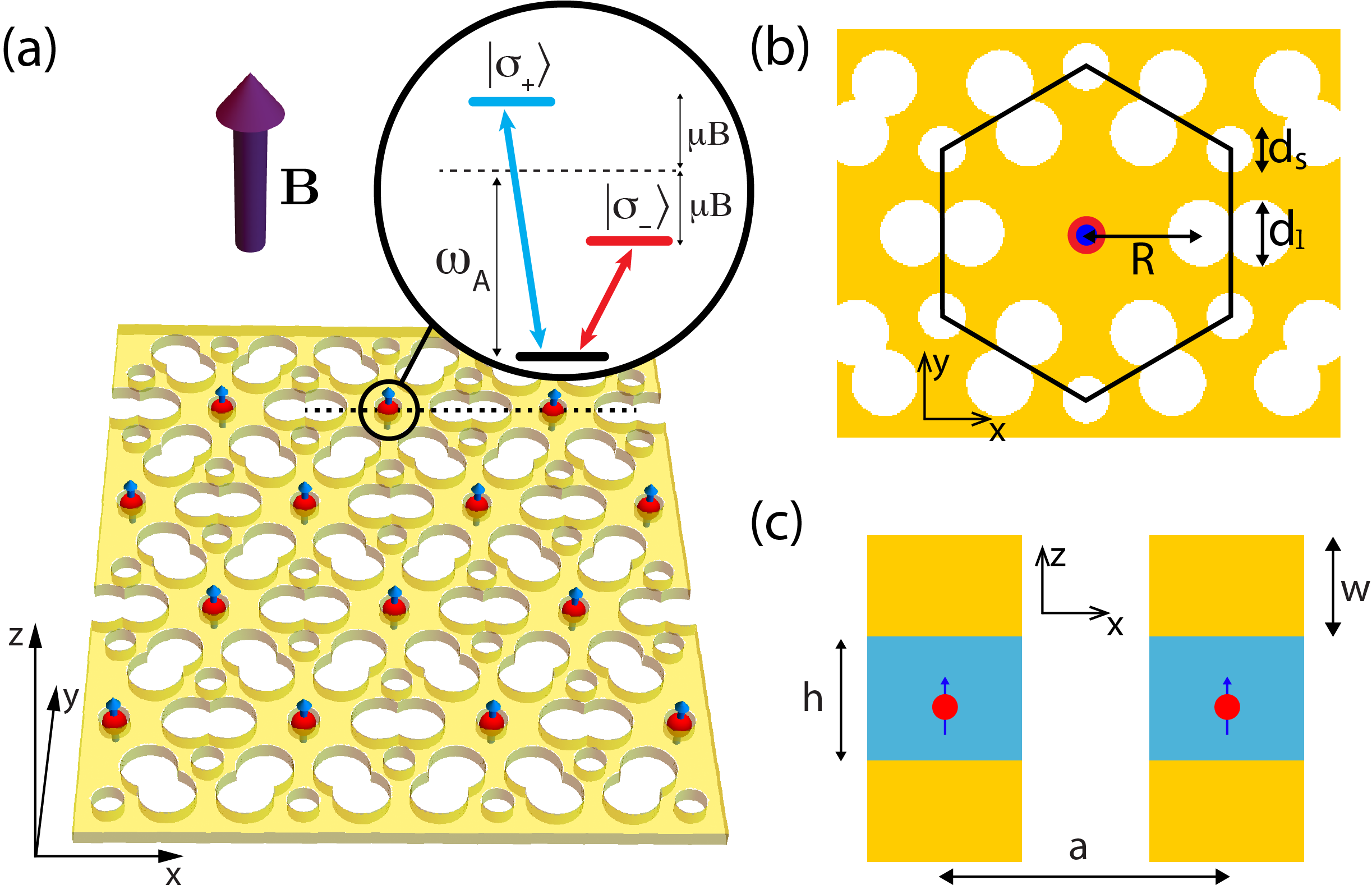
In this manuscript, we propose a novel, realistic interface between a two-dimensional photonic crystal and an atomic emitter array, whose combined properties address all of the above issues to realize a robust topological system with strong interactions at optical frequencies. Specifically, we consider a two-dimensional atomic emitter array integrated with a two dimensional photonic crystal slab. We show that in the presence of an out-of-plane magnetic field, the hybridization of the atomic levels and the photonic modes of the slab lead to energy bands with non-trivial Chern numbers. In contrast to free-space realizations, we find very large topological band gaps and the existence of an almost completely flat topological band. This makes the system a strong candidate for the realization of fractional phases, such as fractional Chern insulators Neupert et al. (2011); Tang et al. (2011); Sun et al. (2011); Peter et al. (2015); Yao et al. (2012, 2013). We also demonstrate that topological edge states form on the system boundary that are robust to imperfections in the lattice and inhomogeneous broadening of the emitters. Notably, the required lattice spacing of the emitters is comparable to the optical wavelength, which is an order of magnitude larger than for free-space systems Perczel et al. (2017a, b); Bettles et al. (2017). The hybrid approach considered here thus opens up a rich and experimentally accessible platform for exploring topological quantum optics and many-body physics.
Fig. 1(a) provides a schematic depiction of the physical system. A triangular lattice of quantum emitters with spacing is embedded in a two-dimensional photonic crystal (PhC) slab of air holes. Each atomic emitter has two optical transitions with wavelength between the ground state and the two excited states and and is surrounded by a cavity-like hole structure. The emitters interact primarily via the guided modes of the slab. A uniform out-of-plane magnetic field Zeeman-splits the excited states of each emitter. The resulting hybridized polaritonic bands feature non-trivial Chern numbers and one of the topological bands is almost completely flat (Fig. 2(b)). In addition, a large energy gap is formed between the bands, which is two orders of magnitude larger than the gap in free space for comparable emitter spacings Perczel et al. (2017a, b). Inside the gap topological edge states appear, which are protected by the large gap from scattering into extended bulk states or the guided modes of the slab and have a large group velocity. Thus these modes carry energy around the system boundary rapidly with minimal losses even in the presence of lattice imperfections and inhomogeneous emitter broadening.
For concreteness, we now focus on the hybrid PhC structure illustrated in Fig. 1. The hexagonal unit cell of the PhC slab made of gallium phosphate (GaP) with air holes is shown in Fig. 1(b). Each atomic emitter is placed at the geometric center of the unit cell, forming a periodic triangular lattice. In addition, the emitters are placed in the middle of the slab (in the mirror plane) to ensure that they only couple to TE-like guided modes Joannopoulos et al. (2008). Such an arrangement can be achieved for different kinds of quantum emitters by introducing slight modifications to the PhC structure. One option is to embed quantum dots directly into the dielectric slab Javadi et al. (2015); Sun et al. (2016); Lodahl et al. (2015); Arcari et al. (2014); Söllner et al. (2015); Barik et al. (2018). Another option is to create an additional hole at the center of the cell and trap a neutral atom in the plane using a combination of far-off resonance optical trapping, vacuum forces and side illumination González-Tudela et al. (2015) (see also Refs. Thompson et al. (2013); Tiecke et al. (2014); Hood et al. (2016); Goban et al. (2015, 2014); Yu et al. (2014)). Alternatively, atom-like color defects in diamond such as Silicon Vacancy (SiV) color centers can be integrated with the photonic structure Faraon et al. (2012); Riedrich-Möller et al. (2014); Sipahigil et al. (2016), by using a thin diamond layer sandwiched between two layers of GaP as shown in Fig. 1(c).
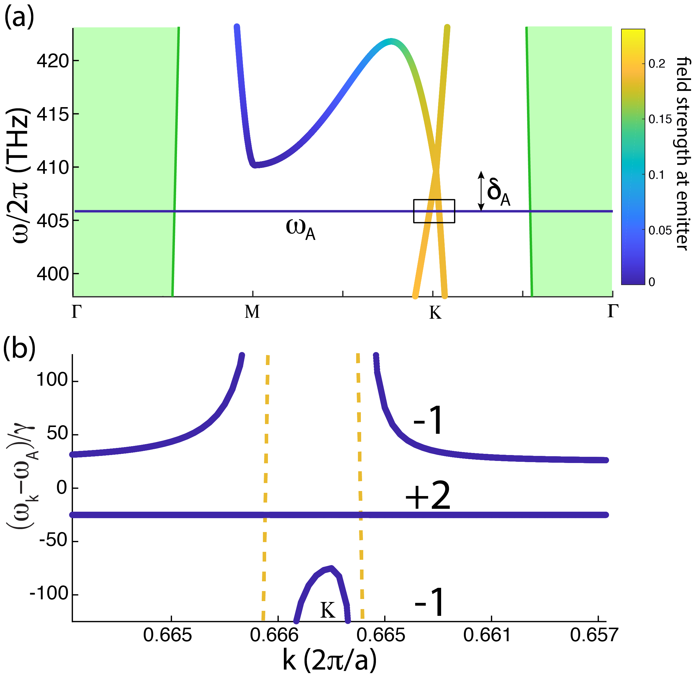
The TE-like guided bands of the slab near the emitter frequency are shown in Fig. 2(a) SM_ . The colors of the bands indicate the normalized field strength at the location of the emitter inside the unit cell, where denotes the classical field solutions of Maxwell’s equations for Bloch quasi-momentum Glauber and Lewenstein (1991); Perczel et al. (2018); Joannopoulos et al. (2008); SM_ . This photonic structure was specifically designed to ensure that there are no other guided modes within a few THz energy range just below the tip of the Dirac cone. Such a photonic spectrum is a general feature of PhC slabs with the cavity-like hole structure shown in Fig. 1(b) and can be achieved for a wide range of geometric and material parameters Perczel and Lukin (2018). The thickness of the layers and the size and spacing of the holes of the diamond-GaP structure are chosen such that the tip of the Dirac cone is tuned within a few hundred GHz of , the transition frequency of the SiV emitters (nm). Thus the emitters interact primarily through the guided modes of the Dirac cone.
The dynamics of the embedded emitters (no-jump evolution in the master equation) in the presence of a magnetic field can be described by the following non-Hermitian Hamiltonian Antezza and Castin (2009); Shahmoon et al. (2017); Bienaimé et al. (2012); Guerin et al. (2016); Perczel et al. (2017a, b)
| (1) |
where is the number of atoms, we define , is the Zeeman-shift of the emitters with magnetic moment due to the magnetic field , is the emission rate of SiVs in bulk diamond, is the speed of light and is the refractive index of diamond. The dipolar spin-spin interaction of emitters is described by the dyadic Green’s function and denotes the position of the atom. The irreversible decay rate of individual emitters inside the slab is given by , where and account for the coupling of the emitters to the guided slab modes and free-space modes, respectively. In general, due to total internal reflection at the surfaces of the patterned slab Arcari et al. (2014). Thus, for now we neglect coupling to free-space modes. (The effect of coupling to free-space photons is discussed in detail in Ref. SM_ .)
The single excitation eigenmodes of Eq. ( Topological quantum optics using atom-like emitter arrays coupled to photonic crystals) are Bloch modes of the form
| (2) |
where the summation runs over all lattice vectors and is the Bloch quasi-momentum. For each , there are two eigenvalues that can be numerically calculated from the photonic band structure shown in Fig. 2(a) SM_ . Fig. 2(b) shows the hybridized atomic-photonic bands in the immediate vicinity of the symmetry point in the presence of an out-of-plane magnetic field. The bare photonic bands of the Dirac cone are also shown schematically as yellow dashed lines for reference. One of the atomic bands does not interact with the guided slab modes due to polarization mismatch, forming a flat band in the middle. The other atomic band hybridizes with the guided modes, forming avoided crossings that split the band into two disjoint parts. Two equal band gaps form just above and below the middle band and the three bands have Chern numbers -1, +2 and -1, respectively.
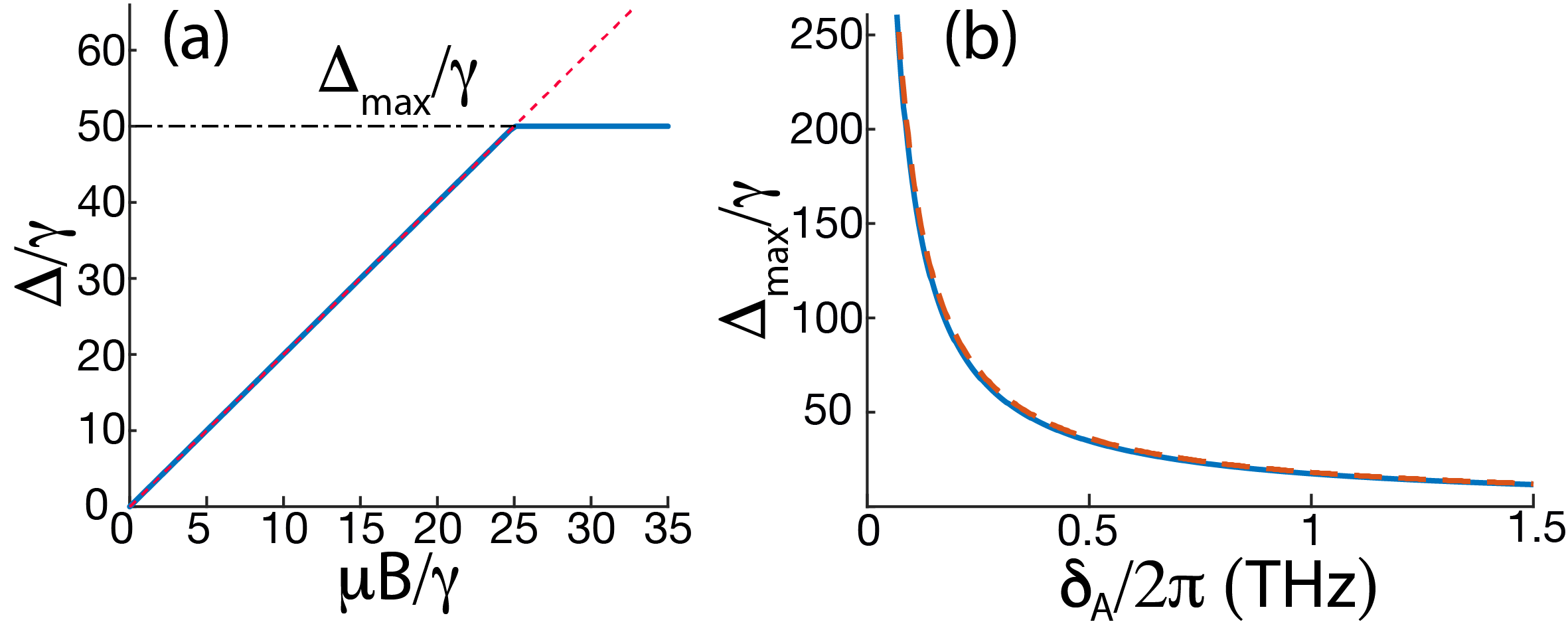
The size of the band gap between topological bands is of particular importance, since the topological protection of the system (e.g. the robustness of edge states to defects) increases with gap size. Since the gap arises from the Zeeman-splitting of the atomic levels Perczel et al. (2017a), the gap size is a linear function of the applied magnetic field (Fig. 3(a)), until a plateau is reached at when the middle band completely flattens. The maximum achievable gap size is plotted in Fig. 3(b) as a function of . As the tip of the photonic Dirac cone is tuned closer to the atomic frequency, the energy gap increases as . Ultimately, the gap size is limited by the fact that our quantum optical model (which relies on the accuracy of the Markov approximation near the Dirac cone González-Tudela and Cirac (2018)) is only valid as long as the emitter-field correlation time is much shorter than the typical timescale on which the atomic system evolves (see Ref. SM_ for more details).
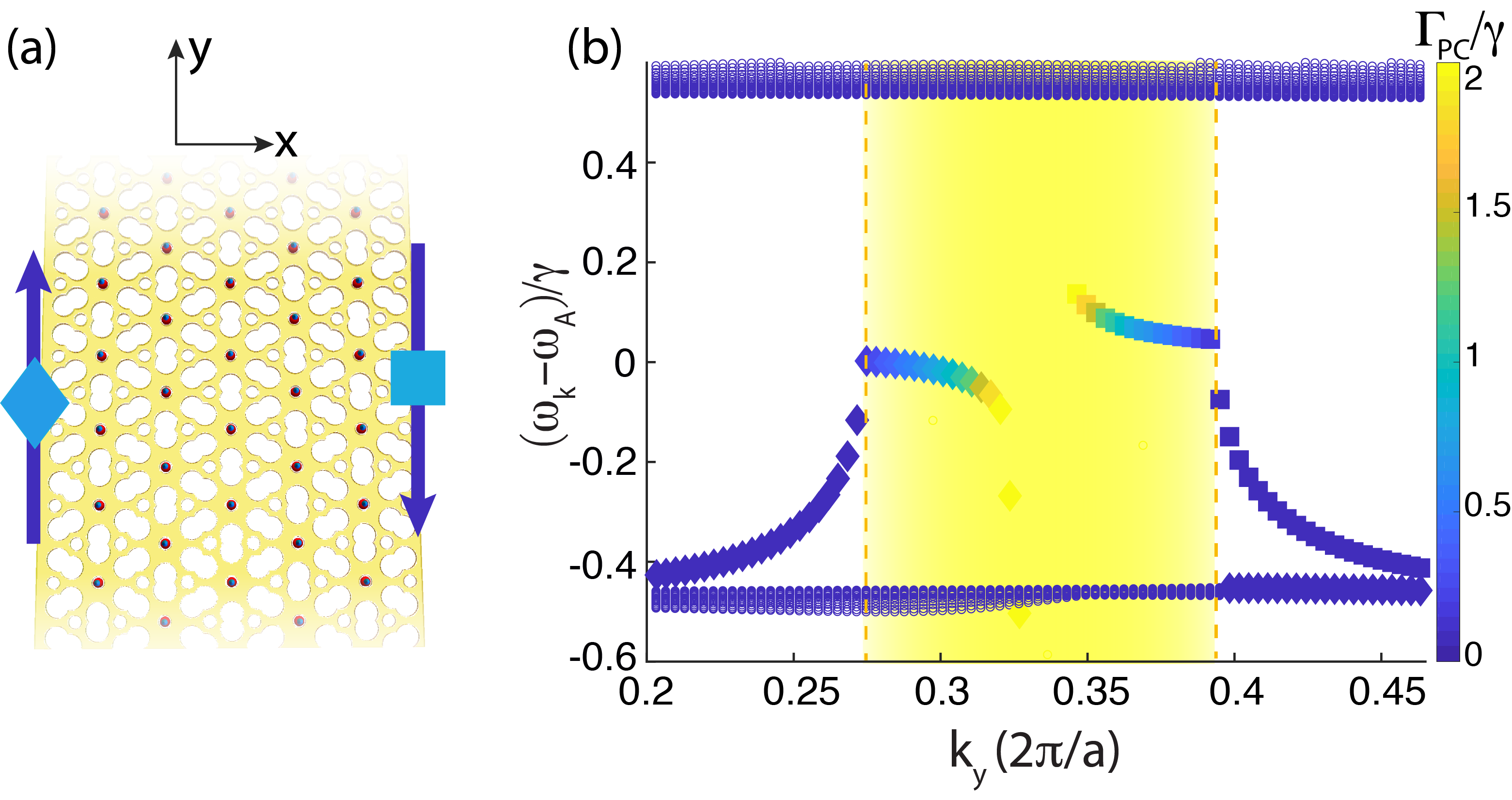
We next explore the topological edge states of the system. We consider a stripe of emitters, embedded in an extended PhC, that is infinite along the -axis, but finite along the -axis as shown in Fig. 4(a). Fig. 4(b) shows the unidirectional edge states inside the gap near the point foo . These states are confined to the system boundaries and carry energy only in a single direction, reflecting the broken time-reversal symmetry and the topological protection of the system Laughlin (1981); Halperin (1982); Haldane and Raghu (2008); Raghu and Haldane (2008); Wang et al. (2008); Perczel et al. (2017a, b). Edge states on the left side of the stripe are marked with triangles, whereas edge states on the right side are marked with squares. The quasi-momentum region where the guided modes of the Dirac cone are resonant with the emitters is shaded yellow and its boundaries are marked by yellow dashed lines (see yellow dashed lines in Fig. 2(b) for reference). In this region the emitters can directly couple to guided slab modes with decay rate , the magnitude of which is indicated in the figure by the color code. Modes that fall outside the yellow region cannot couple to slab modes due to the momentum mismatch, making these modes long-lived. Note that a different edge termination with slightly different edge state properties is obtained when the triangular lattice is rotated relative to the one shown in Fig. 4(a) (see Ref. SM_ for more details).
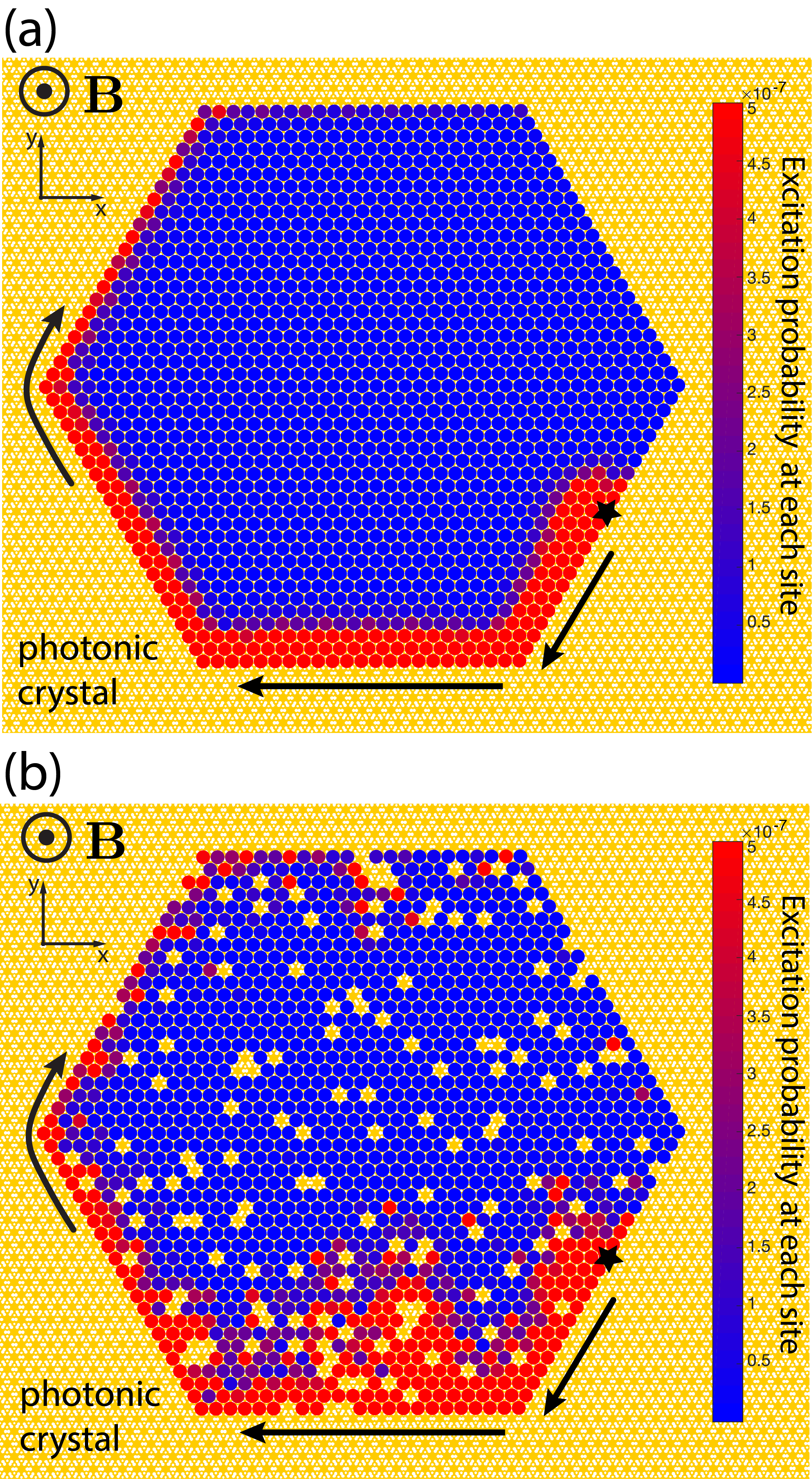
Next, we study the time evolution of edge states in real space. Fig. 5(a) shows a defect-free triangular lattice of emitters with a hexagonal shape. The emitters are embedded in an extended PhC, whose spatial dimensions are much larger than those of the atomic lattice. We assume that one emitter on the edge is addressed by a weak laser with frequency that is resonant with the edge states in the lower half of the gap. The laser couples to the and transitions with equal strength , such that . We calculate the time evolution of the wavefunction of the initial state by numerically exponentiating Eq. ( Topological quantum optics using atom-like emitter arrays coupled to photonic crystals) Perczel et al. (2017b). The evolved state of the system at one particular time is shown in Fig. 5(a), where the color of each site reflects the excitation probability of the emitter. The edge states excited by the laser carry energy only in the clock-wise direction, reflecting the broken time-reversal symmetry of the system. Coupling to bulk modes is strongly suppressed. Furthermore, the excitation routes around the lattice corners without reflection or significant loss into the guided modes of the slab.
The hallmark of topological edge states is their robustness to significant imperfections in the system. Fig. 5(b) shows a lattice, where a random of the emitters is missing. Furthermore, we assume that the inhomogeneities in the nanophotonic environment (e.g. fabrication imperfections) give rise to the inhomogeneous broadening of emitters. Therefore, we sample the emitter frequencies from a Gaussian distribution, whose width is 10% of the gap. Fig. 5(b) shows a snapshot of the time-evolved state of the system. Despite the presence of the lattice defects and the inhomogeneity of emitters, the edge state propagates along the system edges, routing around all defects, including the cluster of missing emitters near the bottom edge. These results demonstrate the topological robustness of the edge states and the system as a whole.
The flat middle band in Fig. 2(b) is another key feature of our topological system. The flatness of the band and the non-trivial Chern number are, in general, the two key ingredients for fractionalized topological phases in lattice models Neupert et al. (2011); Tang et al. (2011); Sun et al. (2011); Peter et al. (2015); Yao et al. (2012, 2013); Wang et al. (2012); Yang et al. (2012); Trescher and Bergholtz (2012). Usually, such flat bands require careful tuning of the long-range hopping parameters. Here, away from the point the band remains flat due to the fact that the guided photonic bands are far-detuned and coupling to them is weak (Fig. 2(a)). Near the point, flatness arises from the combined effects of the uniform magnetic field and the fact that the middle band does not couple to the PhC bands due to polarization mismatch. The inherent non-linearity of the constituent emitters gives rise to a hard-core constraint for the bosonic excitations of the system, which provides a point-like interaction for the excitations. Such short-range interactions are ideal for the realization of interacting many-body topological phases Gong et al. (2016). Within such a system we expect non-trivial competition between states with strongly correlated topological phases and those that behave analogously to electronic charge density waves. This competition arises from the fact that the atoms interact primarily through the Dirac cone and, therefore, the Berry curvature is concentrated in the vicinity of the points. Thus only states near the points are expected to yield exotic topological many-body phases, whereas the rest of the band will likely contribute to states that resemble an ordered quantum fluid. Controlling the distribution of the Berry curvature in the flat band (e.g. using established techniques from cold atom experiments He et al. (2017)) can be explored for engineering experimentally observable fractional topological phases. This will be addressed in forthcoming work.
While practical realization of the proposed systems constitutes a non-trivial challenge, most of the key ingredients have already been demonstrated recently. For example, a hybrid system based on SiV color defects in diamond can be created by first fabricating a thin diamond slab Faraon et al. (2012); Wan et al. (2018), SiVs can be implanted using focused ion beam implantation Pacheco et al. (2017), while GaP can be positioned on both sides of the slab Aparna et al. (2014) with the air-hole structure created by etching through the GaP and diamond layers. Alternatively, a PhC hole structure made entirely of diamond can potentially be used (see Ref. SM_ for more details).
We have demonstrated that two-dimensional quantum emitter arrays embedded in photonic crystals constitute a topological quantum optical system. The atomic bands have non-trivial Chern numbers in the presence of an out-of-plane magnetic field and the dispersion of one of the bands is significantly quenched. Long-lived topological edge states appear on the system boundaries, which are robust to imperfect lattice filling as well as to inhomogeneous broadening of the emitters. We believe that the experimental accessibility of this platform will open up exciting opportunities for exploring novel topological states of light and matter, including quantum optical analogues of fractional Chern insulators.
We would like to thank Mihir Bhaskar, Ruffin Evans, Alejandro González-Tudela, Fabian Grusdt, Bert Halperin, Hannes Pichler, Denis Sukachev, Efraim Shahmoon, Dominik Wild, Bihui Zhu and Peter Zoller for valuable discussions. This work was supported through the National Science Foundation (NSF), the MIT-Harvard Center for Ultracold Atoms, the Air Force Office of Scientific Research via the MURI, the Vannevar Bush Faculty Fellowship and DOE. Some of the computations in this paper were performed on the Odyssey cluster supported by the FAS Division of Science, Research Computing Group at Harvard University. J. P. acknowledges support from the Dr. Elemér and Éva Kiss Scholarship Fund. J. B. acknowledges support from the European Research Council (ERC Grant Agreement no. 337603) and VILLUM FONDEN via the QMATH Centre of Excellence (Grant no. 10059). D. E. C. acknowledges support from the ERC Starting Grant FOQAL, MINECO Plan Nacional Grant CANS, MINECO Severo Ochoa Grant No. SEV-2015-0522, CERCA Programme/Generalitat de Catalunya, Fundacio Privada Cellex and AGAUR Grant 2017 SGR 1334.
References
- Klitzing et al. (1980) K. V. Klitzing, G. Dorda, and M. Pepper, Physical Review Letters 45, 494 (1980).
- Tsui et al. (1982) D. C. Tsui, H. L. Stormer, and A. C. Gossard, Physical Review Letters 48, 1559 (1982).
- Konig et al. (2007) M. Konig, S. Wiedmann, C. Brune, A. Roth, H. Buhmann, L. W. Molenkamp, X.-L. Qi, and S.-C. Zhang, Science 318, 766 (2007).
- Haldane and Raghu (2008) F. D. M. Haldane and S. Raghu, Physical Review Letters 100, 013904 (2008).
- Raghu and Haldane (2008) S. Raghu and F. D. M. Haldane, Physical Review A 78, 033834 (2008).
- Wang et al. (2008) Z. Wang, Y. D. Chong, J. D. Joannopoulos, and M. Soljačić, Physical Review Letters 100, 013905 (2008).
- Liu et al. (2012) K. Liu, L. Shen, and S. He, Optics Letters 37, 4110 (2012).
- Wang et al. (2009) Z. Wang, Y. Chong, J. D. Joannopoulos, and M. Soljačić, Nature 461, 772 (2009).
- Yu et al. (2008) Z. Yu, G. Veronis, Z. Wang, and S. Fan, Physical Review Letters 100, 023902 (2008).
- Rechtsman et al. (2013) M. C. Rechtsman, J. M. Zeuner, Y. Plotnik, Y. Lumer, D. Podolsky, F. Dreisow, S. Nolte, M. Segev, and A. Szameit, Nature 496, 196 (2013).
- Hafezi et al. (2011) M. Hafezi, E. A. Demler, M. D. Lukin, and J. M. Taylor, Nature Physics 7, 907 (2011).
- Hafezi et al. (2013) M. Hafezi, S. Mittal, J. Fan, A. Migdall, and J. M. Taylor, Nature Photonics 7, 1001 (2013).
- Fang et al. (2012) K. Fang, Z. Yu, and S. Fan, Nature Photonics 6, 782 (2012).
- Khanikaev et al. (2015) A. B. Khanikaev, R. Fleury, S. H. Mousavi, and A. Alù, Nature Communications 6, 8260 (2015).
- Yang et al. (2015) Z. Yang, F. Gao, X. Shi, X. Lin, Z. Gao, Y. Chong, and B. Zhang, Physical Review Letters 114, 114301 (2015).
- Lu et al. (2017) J. Lu, C. Qiu, L. Ye, X. Fan, M. Ke, F. Zhang, and Z. Liu, Nature Physics 13, 369 (2017).
- Susstrunk and Huber (2015) R. Susstrunk and S. D. Huber, Science 349, 47 (2015).
- Mousavi et al. (2015) S. H. Mousavi, A. B. Khanikaev, and Z. Wang, Nature Communications 6, 8682 (2015).
- Nash et al. (2015) L. M. Nash, D. Kleckner, A. Read, V. Vitelli, A. M. Turner, and W. T. M. Irvine, Proceedings of the National Academy of Sciences of the United States of America 112, 14495 (2015).
- Dalibard et al. (2011) J. Dalibard, F. Gerbier, G. Juzeliūnas, and P. Öhberg, Reviews of Modern Physics 83, 1523 (2011).
- Eckardt (2017) A. Eckardt, Reviews of Modern Physics 89, 011004 (2017).
- Lu et al. (2014) L. Lu, J. D. Joannopoulos, and M. Soljačić, Nature Photonics 8, 821 (2014).
- Huber (2016) S. D. Huber, Nature Physics 12, 621 (2016).
- Laughlin (1981) R. B. Laughlin, Physical Review B 23, 5632 (1981).
- Halperin (1982) B. I. Halperin, Physical Review B 25, 2185 (1982).
- Laughlin (1983) R. B. Laughlin, Physical Review Letters 50, 1395 (1983).
- Perczel et al. (2017a) J. Perczel, J. Borregaard, D. Chang, H. Pichler, S. Yelin, P. Zoller, and M. Lukin, Physical Review Letters 119, 023603 (2017a).
- Perczel et al. (2017b) J. Perczel, J. Borregaard, D. E. Chang, H. Pichler, S. F. Yelin, P. Zoller, and M. D. Lukin, Physical Review A 96, 063801 (2017b).
- Bettles et al. (2017) R. J. Bettles, J. Minář, C. S. Adams, I. Lesanovsky, and B. Olmos, Physical Review A 96, 041603 (2017).
- Carusotto and Ciuti (2013) I. Carusotto and C. Ciuti, Reviews of Modern Physics 85, 299 (2013).
- González-Tudela et al. (2015) A. González-Tudela, C.-L. Hung, D. E. Chang, J. I. Cirac, and H. J. Kimble, Nature Photonics 9, 320 (2015).
- Douglas et al. (2015) J. S. Douglas, H. Habibian, C.-L. Hung, A. V. Gorshkov, H. J. Kimble, and D. E. Chang, Nature Photonics 9, 326 (2015).
- Lodahl et al. (2017) P. Lodahl, S. Mahmoodian, S. Stobbe, A. Rauschenbeutel, P. Schneeweiss, J. Volz, H. Pichler, and P. Zoller, Nature 541, 473 (2017).
- Angelakis (2017) D. G. Angelakis, Quantum Science and Technology, edited by D. G. Angelakis, Quantum Science and Technology (Springer International Publishing, Cham, 2017) p. 214.
- Cirac and Kimble (2017) J. I. Cirac and H. J. Kimble, Nature Photonics 11, 18 (2017).
- Barik et al. (2018) S. Barik, A. Karasahin, C. Flower, T. Cai, H. Miyake, W. DeGottardi, M. Hafezi, and E. Waks, Science (New York, N.Y.) 359, 666 (2018).
- Neupert et al. (2011) T. Neupert, L. Santos, C. Chamon, and C. Mudry, Physical Review Letters 106, 236804 (2011).
- Tang et al. (2011) E. Tang, J.-W. Mei, and X.-G. Wen, Physical Review Letters 106, 236802 (2011).
- Sun et al. (2011) K. Sun, Z. Gu, H. Katsura, and S. Das Sarma, Physical Review Letters 106, 236803 (2011).
- Peter et al. (2015) D. Peter, N. Y. Yao, N. Lang, S. D. Huber, M. D. Lukin, and H. P. Büchler, Physical Review A 91, 053617 (2015).
- Yao et al. (2012) N. Y. Yao, C. R. Laumann, A. V. Gorshkov, S. D. Bennett, E. Demler, P. Zoller, and M. D. Lukin, Physical Review Letters 109, 266804 (2012).
- Yao et al. (2013) N. Y. Yao, A. V. Gorshkov, C. R. Laumann, A. M. Läuchli, J. Ye, and M. D. Lukin, Physical Review Letters 110, 185302 (2013).
- Sangouard et al. (2011) N. Sangouard, C. Simon, H. de Riedmatten, and N. Gisin, Reviews of Modern Physics 83, 33 (2011).
- Joannopoulos et al. (2008) J. D. Joannopoulos, S. G. Johnson, J. N. Winn, and R. D. Meade, Photonic Crystals: Molding the Flow of Light (Second Edition). (Princeton University Press, 2008) p. 446.
- Javadi et al. (2015) A. Javadi, I. Söllner, M. Arcari, S. L. Hansen, L. Midolo, S. Mahmoodian, G. Kiršanskė, T. Pregnolato, E. H. Lee, J. D. Song, S. Stobbe, and P. Lodahl, Nature Communications 6, 8655 (2015).
- Sun et al. (2016) S. Sun, H. Kim, G. S. Solomon, and E. Waks, Nature Nanotechnology 11, 539 (2016).
- Lodahl et al. (2015) P. Lodahl, S. Mahmoodian, and S. Stobbe, Reviews of Modern Physics 87, 347 (2015).
- Arcari et al. (2014) M. Arcari, I. Söllner, A. Javadi, S. Lindskov Hansen, S. Mahmoodian, J. Liu, H. Thyrrestrup, E. Lee, J. Song, S. Stobbe, and P. Lodahl, Physical Review Letters 113, 093603 (2014).
- Söllner et al. (2015) I. Söllner, S. Mahmoodian, S. L. Hansen, L. Midolo, A. Javadi, G. Kiršanskė, T. Pregnolato, H. El-Ella, E. H. Lee, J. D. Song, S. Stobbe, and P. Lodahl, Nature Nanotechnology 10, 775 (2015).
- Thompson et al. (2013) J. D. Thompson, T. G. Tiecke, N. P. de Leon, J. Feist, A. V. Akimov, M. Gullans, A. S. Zibrov, V. Vuletic, and M. D. Lukin, Science 340, 1202 (2013).
- Tiecke et al. (2014) T. G. Tiecke, J. D. Thompson, N. P. de Leon, L. R. Liu, V. Vuletić, and M. D. Lukin, , 8 (2014).
- Hood et al. (2016) J. D. Hood, A. Goban, A. Asenjo-Garcia, M. Lu, S.-P. Yu, D. E. Chang, and H. J. Kimble, Proceedings of the National Academy of Sciences of the United States of America 113, 10507 (2016).
- Goban et al. (2015) A. Goban, C.-L. Hung, J. Hood, S.-P. Yu, J. Muniz, O. Painter, and H. Kimble, Physical Review Letters 115, 063601 (2015).
- Goban et al. (2014) A. Goban, C.-L. Hung, S.-P. Yu, J. Hood, J. Muniz, J. Lee, M. Martin, A. McClung, K. Choi, D. Chang, O. Painter, and H. Kimble, Nature Communications 5, 3808 (2014).
- Yu et al. (2014) S.-P. Yu, J. D. Hood, J. A. Muniz, M. J. Martin, R. Norte, C.-L. Hung, S. M. Meenehan, J. D. Cohen, O. Painter, and H. J. Kimble, Applied Physics Letters 104, 111103 (2014).
- Faraon et al. (2012) A. Faraon, C. Santori, Z. Huang, V. M. Acosta, and R. G. Beausoleil, Physical Review Letters 109, 033604 (2012).
- Riedrich-Möller et al. (2014) J. Riedrich-Möller, C. Arend, C. Pauly, F. Mücklich, M. Fischer, S. Gsell, M. Schreck, and C. Becher, Nano Letters 14, 5281 (2014).
- Sipahigil et al. (2016) A. Sipahigil, R. E. Evans, D. D. Sukachev, M. J. Burek, J. Borregaard, M. K. Bhaskar, C. T. Nguyen, J. L. Pacheco, H. A. Atikian, C. Meuwly, R. M. Camacho, F. Jelezko, E. Bielejec, H. Park, M. Lončar, and M. D. Lukin, Science 354, 847 (2016).
- (59) See Supplemental Material for more details.
- Glauber and Lewenstein (1991) R. J. Glauber and M. Lewenstein, Physical Review A 43, 467 (1991).
- Perczel et al. (2018) J. Perczel, P. Kómár, and M. D. Lukin, Physical Review A 98, 033803 (2018).
- Perczel and Lukin (2018) J. Perczel and M. D. Lukin, (2018), arXiv:1810.12815 .
- Antezza and Castin (2009) M. Antezza and Y. Castin, Physical Review Letters 103, 123903 (2009).
- Shahmoon et al. (2017) E. Shahmoon, D. S. Wild, M. D. Lukin, and S. F. Yelin, Physical Review Letters 118, 113601 (2017).
- Bienaimé et al. (2012) T. Bienaimé, N. Piovella, and R. Kaiser, Physical Review Letters 108, 123602 (2012).
- Guerin et al. (2016) W. Guerin, M. O. Araújo, and R. Kaiser, Physical Review Letters 116, 083601 (2016).
- Karzig et al. (2015) T. Karzig, C.-E. Bardyn, N. H. Lindner, and G. Refael, Physical Review X 5, 031001 (2015).
- González-Tudela and Cirac (2018) A. González-Tudela and J. I. Cirac, Physical Review A 97, 043831 (2018).
- Evans et al. (2016) R. E. Evans, A. Sipahigil, D. D. Sukachev, A. S. Zibrov, and M. D. Lukin, Physical Review Applied 5, 044010 (2016).
- (70) Note that all edge state calculations are performed for a small gap size (i.e. large ) to ensure sufficient density of states even for limited lattice sizes.
- Wang et al. (2012) Y.-F. Wang, H. Yao, C.-D. Gong, and D. N. Sheng, Physical Review B 86, 201101 (2012).
- Yang et al. (2012) S. Yang, Z.-C. Gu, K. Sun, and S. Das Sarma, Physical Review B 86, 241112 (2012).
- Trescher and Bergholtz (2012) M. Trescher and E. J. Bergholtz, Physical Review B 86, 241111 (2012).
- Gong et al. (2016) Z.-X. Gong, M. F. Maghrebi, A. Hu, M. L. Wall, M. Foss-Feig, and A. V. Gorshkov, Physical Review B 93, 041102 (2016).
- He et al. (2017) Y.-C. He, F. Grusdt, A. Kaufman, M. Greiner, and A. Vishwanath, Physical Review B 96, 201103 (2017).
- Wan et al. (2018) N. H. Wan, S. Mouradian, and D. Englund, Applied Physics Letters 112, 141102 (2018).
- Pacheco et al. (2017) J. L. Pacheco, M. Singh, D. L. Perry, J. R. Wendt, G. Ten Eyck, R. P. Manginell, T. Pluym, D. R. Luhman, M. P. Lilly, M. S. Carroll, and E. Bielejec, Review of Scientific Instruments 88, 123301 (2017).
- Aparna et al. (2014) A. Aparna, V. Brahmajirao, and T. Karthikeyan, Procedia Materials Science 6, 1650 (2014).
Supplemental Material
The Supplemental Material is organized as follows. In Sec. 1, we discuss the calculations for obtaining the atomic band structure. In Sec. 2, we describe the real-space Green’s function and its properties. In Sec. 3, we discuss the validity of our model and the limits on the maximum achievable gap size in our system. In Sec. 4, we describe the calculations behind obtaining the edge states in our system. Finally, in Sec. 5, we analyze the edge states in the presence of free space decay.
I Calculation of the atomic band structure
In this section, we calculate the Bloch modes of the hybrid emitter-photonic crystal system. For simplicity, we focus on the atomic interactions mediated by the photonic crystal modes and neglect coupling to free-space photons. This is motivated by previous studies of a triangular lattice of emitters in free space Perczel et al. (2017a). The cooperative effects mediated by free-space photons reported in Ref. Perczel et al. (2017a) are, in general, an order magnitude smaller than those mediated by the photonic crystal modes described here.
I.1 Analytic calculations
The Bloch eigenmodes of our system with quasi-momentum can be obtained by substituting Eqs. (1) and (4) from the Main Text into . After transforming to a Cartesian basis using the relation , the Bloch modes are obtained by diagonalizing the following 2x2 matrix
| (S1) | |||||
where label the polarization components and denotes the ‘dressed’ atomic transition frequency in the photonic crystal. The summation is implied over the set of triangular lattice vectors , where and
| (S2) |
The Zeeman splitting of the atomic levels is given by
| (S3) |
To simplify Eq. (S1), we write the atomic transition frequency as
| (S4) |
where is the ‘bare’ atomic transition in bulk diamond and is the energy shift of the individual atoms due to the presence of the photonic crystal environment. We make use of the fact that
| (S5) |
to rewrite Eq. (S1) as
| (S6) |
Generally, it is difficult to work with the Green’s function in real space, due to the slow convergence of the sum above. Therefore, it is convenient to transform the summation over real-space lattice vectors to a summation over momentum-space reciprocal lattice vectors , where
| (S7) |
The momentum-space summation can be performed over the Fourier-transform of the Green’s function in momentum space.
In particular, we substitute into Eq. (S6) the following expression
| (S8) |
where the integral is performed over the irreducible Brillouin zone of the photonic crystal and stands for the Green’s function in momentum space. Next, we make use of the following form of Poisson’s identity
| (S9) |
to transform the summation to momentum space, where is the area of the hexagonal unit cell in real space. We perform the integral to obtain
| (S10) |
where the first equality follows from the fact that only the Dirac delta with contributes to the integral (since the integral is restricted to the irreducible Brillouin zone), and the second equality follows from time-reversal symmetry of the photonic crystal spectrum Bernevig and Hughes (2013). Using this expression, we can rewrite Eq. (S6) as
| (S11) |
Finally, we expess the momentum-space Green’s function in terms of its eigenvalue expansion Perczel et al. (2018) as
| (S12) |
where denotes the component () of the electric field of the photonic crystal mode in the band at quasi-momentum , while is the corresponding frequency of the mode.
Even though gives the electric field distribution inside the entire real-space unit cell, we only sample the field at the position of the emitter (), which we choose to be at the geometric center of the hexagonal cell and to ensure that the emitter only couples to TE-like modes Joannopoulos et al. (2008).
Due to the underlying periodicity of the photonic crystal lattice, the electric field mode can be expressed in a canonical Bloch form as
| (S13) |
where is the periodicity of the lattice and is a dimensionless periodic vector function that is normalized to ensure that
| (S14) |
where is the periodic dielectric permittivity function describing the photonic crystal in real space and the integral is performed over the quantization volume Glauber and Lewenstein (1991); Perczel et al. (2018).
I.2 Numerical calculations using MPB
We use the open-source MIT Photonic Bands 1.4.2 (MPB) numerical software package Johnson and Joannopoulos (2001) to directly obtain the expressions for and the normalized 111S. G. Johnson, Official MPB Documentation (online), https://mpb.readthedocs.io/en/latest/
Scheme_User_Interface/#field-normalization. MPB is an iterative eigensolver that uses a planewave basis to iteratively improve approximations to the eigenstates and eigenvalues of Maxwell’s equations. MPB approximates the solution using a planewave cutoff, which corresponds to the spatial discretization of the unit cell. In our simulations, we take a supercell of height 4a and run the calculations with a supercell discretization resolution of .
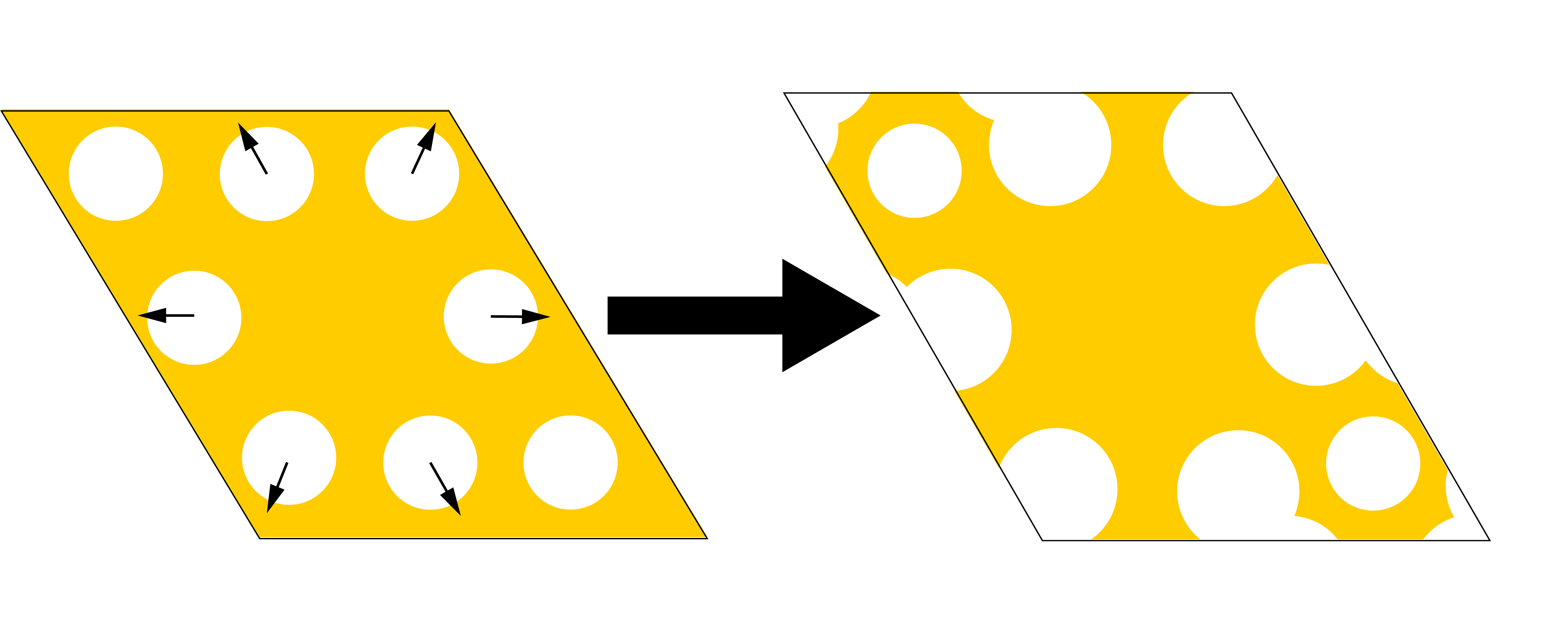
In particular, we perform the numerical calculations by defining a rhombic 2D supercell that contains a triangular array of holes with hole spacing . We remove the central hole and push the surrounding 6 holes radially outward (Fig. S1), such that the center of these 6 holes is a distance away from the center. The radii of these 6 holes is increased to . We leave the other two holes in place, which have a radius of . The slab is composed of three different layers. In the middle, we define a diamond () layer of thickness , which is sandwiched between two GaP () layers of thickness . In the resulting band structure, the tip of the Dirac cone is at . The eigenenergies and the corresponding field intensities of the TE-like modes at the location of the emitters () are plotted in Fig. 2(a) of the Main Text. After substituting and into Eq. (S13) and Eq. (S11), we diagonalize the matrix in Eq. (S12) and we obtain two eigenvalues () for each . The results are plotted in Fig. 2(b) of the Main Text for a non-zero magnetic field.
I.3 All-diamond photonic crystal slab
Note that it is also possible to use an all-diamond photonic crystal with SiVs, which would significantly simply the fabrication process. An all-diamond structure with the cavity-like arrangement of air holes shown in Fig. S1 would also have a stand-alone Dirac cone and give rise to dipolar interactions with winding phases Perczel and Lukin (2018). However, given that diamond has a lower refractive index than GaP, tuning the photonic Dirac cone resonant with the SiVs would require a photonic structure with significantly larger lattice spacing than for the hybrid structure. This reduces the size of the irreducible Brillouin zone in -space to the extent that the entire Brillouin zone falls within the light cone region (). This, in turn, implies that all of the edge states of the system could couple to free-space photons (see Sec. 5. for more details).
II The real-space Green’s function
In order to calculate the time evolution of a finite lattice of emitters (e.g. Fig. 5 in the Main Text), we need to directly substitute the real-space Green’s function into Eq. (1) of the Main Text. The explicit derivation of the real-space Green’s function of our system is discussed in detail in Ref. Perczel and Lukin (2018). Here we simply give its explicit form and briefly describe its properties.
The dipolar coupling mediated by the photonic Dirac cone is described by the following Green’s function Perczel and Lukin (2018)
| (S17) |
where is the position vector, the diagonal (off-diagonal) terms of account for the coupling between atomic transitions of the same (opposite) circular polarization, denotes the Hankel function of the second kind of order and gives the length scale of the interaction as a function of the linear dispersion of the slab modes at the Dirac cone and the atomic detuning from the tip of the Dirac cone . The prefactors are given by
| (S18) |
where is the area of the hexagonal unit cell, is the electric field intensity in the vicinity of the Dirac cone, which is approximately -independent, and and are the quasi-momenta associated with the two inequivalent points in the Brillouin zone. The parameters and are obtained numerically Perczel and Lukin (2018). This analytic Green’s function quantitatively captures the slab-mediated dipolar interaction, when is small. Note the presence of the winding phases Peter et al. (2015); Karzig et al. (2015); Bettles et al. (2017) in the off-diagonal terms of , which give rise to the topological properties of the system. These winding phases arise from the propagation-direction-dependent polarization structure of the photonic modes of the Dirac cone Perczel and Lukin (2018).
III Model validity and maximum gap size
In Fig. 3(b) of the Main Text we found that the size of the gap is inversely proportional to , the detuning of the atomic frequency from the tip of the photonic Dirac cone. Eventually, as is decreased, our theory breaks down, limiting the maximum achievable gap size. In this section we discuss for what parameters this breakdown occurs.
The non-Hermitian Hamiltonian in Eq. (1) of the Main Text describes the evolution of the system in the absence of quantum jumps and is obtained from the canonical master equation for open quantum systems Perczel et al. (2017a). Since the derivation of the master equation assumes the validity of the Born-Markov approximation Gross and Haroche (1982), our results are guaranteed to be valid only as long as these approximations hold. However, the Born-Markov approximation is known to break down as the atomic emitters are tuned close to the Dirac vertex González-Tudela and Cirac (2018).
The Born approximation assumes that the state of the environment (i.e. the collection of photonic crystal modes) is not significantly affected by its interaction with the emitters. This assumption is guarenteed to hold as long as the photonic crystal is much larger than the emitter array.
The Markov approximation assumes that the correlation time between the environment and the emitters is much smaller than the typical time scale for the evolution of the system , (i.e. ). Here, the correlation time of the environment corresponds to the time it takes for a photon to leave the emitter array, since for the photon can still be reabsorbed by another emitter. Denoting the characteristic size of the emitter array with , we find that , where is the group velocity of the guided modes of the photonic crystal slab.
Our focus in this work is the excitation and time evolution of edge states, for which the relevant time scale is , where is the energy gap (recall that the group velocity of the edge states is proportional to ). Thus the Markov approximation requires that
| (S19) |
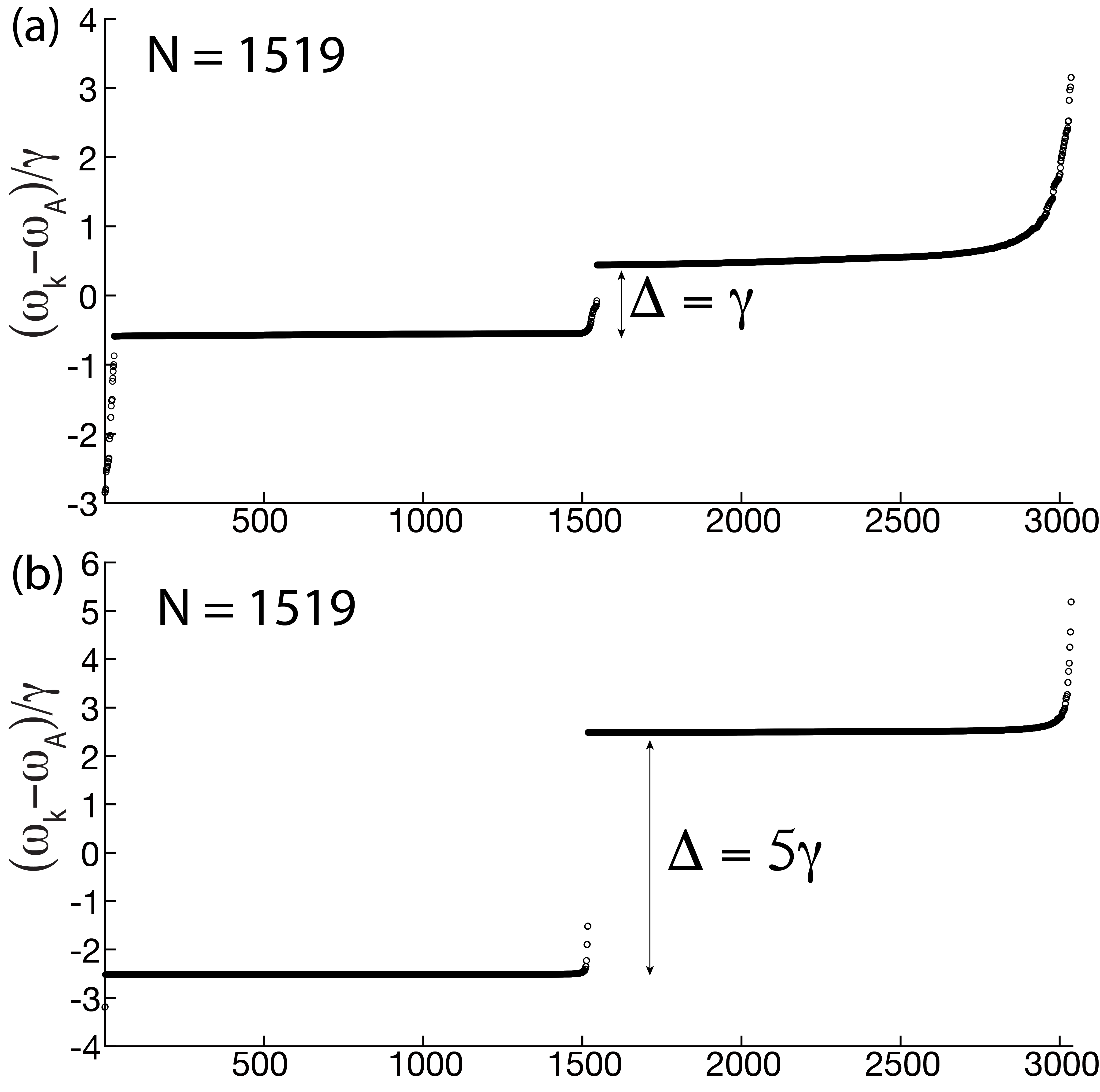
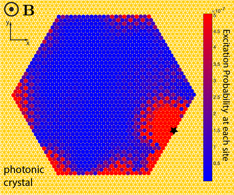
Note that the system size and the gap size cannot be varied independently. The gap size scales as , and as is reduced, the density of photonic states (DOS) through which the emitters interact decreases as . To illustrate how the DOS of the photonic slab modes influences the edges states of our system, in Fig. S2(a) and (b) we plot the spectrum for emitters for (THz) and (THz), respectively. All eigenstates are ordered in ascending order. The energy gap is indicated in both spectra with a double arrow. All eigenstates inside the gap are edge modes. The parameters in Fig. S2(a) correspond to those used for the time-domain simulation in Fig. 5 of the Main Text. Note that the edge states are densely packed in the lower half of the gap. This leads to dispersive edge state propagation on the system boundaries (see Fig. 5 of the Main Text for reference). In contrast, Fig. S2(b) shows the spectrum when is reduced by a factor a 5, leading to a 5 times larger band gap, but also to 5 times fewer edge states in the gap. Fig. S3 shows a snapshot from the time-dynamics when these edge states are excited. Given that only a few modes are excited, no dispersive propagation is observed. Instead, patches of delocalized excitations are formed that appear and disappear as the system evolves in time. This interference effect is the expected behavior for the time evolution of a limited set of modes that have similar energies.
In order to keep the number of edge states inside the gap constant while is increased, the number of emitters has to be increased as . In general, the required number of emitters for dispersive edge state propagation scales approximately as , where we introduced to parameterize the size of the gap as and is a phenomenological constant that we deduce from Fig. S2(a), where . Since the size of the emitter array scales as , we can rewrite Eq. (S19) as
| (S20) |
which, after rearrangement, yields
| (S21) |
Substituting , THz, , nm and , we find that in our system the Markov approximation holds as long as the gap size satisfies
| (S22) |
IV Calculation of edge states
In this section we describe how to numerically calculate the edge states of the system and analyze them in detail.
We consider stripes of atoms that are infinite along one direction and finite in the other as shown schematically in Fig. S4. The periodic unit cells of the stripes are identified with black rectangles. The unit cells for both orientations are also shown with atoms. The set of unit cells form a periodic 1D lattice. For the stripe along the x axis the 1D lattice vector is , whereas for the the axis it is . Here, we describe the calculation of the edge states for the stripe oriented along the axis. The calculation for the other stripe orientation proceeds analogously.
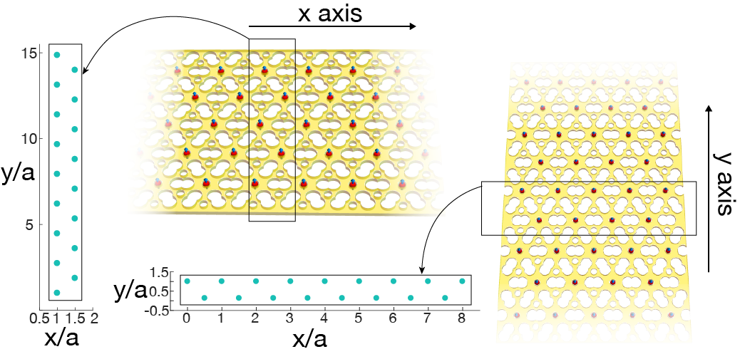
For the stripe oriented along the axis, the Bloch ansatz takes the following form
| (S23) |
where the summation over is implied over all unit cells, which are placed apart along the axis, is the Bloch quasi-momentum and labels each of the emitters inside the unit cell. Acting on Eq. (S23) with the Hamiltonian (Eq. (1) of the Main Text), neglecting the term responsible for coupling to free-space photons and making use of Eq. (S5), we find that the eigenvalues of the stripe can be obtained by diagonalizing the following Hamiltonian
| (S24) | |||||
where we have defined
| (S25) |
where and denote emitter coordinates within a single cell.
Similar to the 2D band structure calculation (see Sec. 1), it is convenient to transform the real-space summation that runs over to a summation in momentum space. In order to perform this transformation over the lattice sites along the -axis, we need to find an expression for the Green’s function that depends on and . Thus, we need to Fourier transform the Green’s function along the -axis only. We express the Green’s function as
| (S26) |
where
| (S27) |
In addition, we also make use of Poisson’s summation formula in the following form
| (S28) |
where is the set of reciprocal lattice vectors along the axis. Using these expressions, we obtain
| (S29) | |||||
where the second equality follows from the fact that only the irreducible Brillouin zone, where , contributes to the summation and from the observation that due to the time-reversal symmetry of the photonic crystal spectrum.
To proceed, we need to numerically evaluate Eq. (S27). Substituting Eq. (S12) into Eq. (S27), we obtain
where and the summation runs over all bands. The sum is dominated by the two bands that constitute the Dirac cone (which we label and ), and there are two inequivalent Dirac cones at the and points. Therefore, to a good approximation, we can rewrite the above expression as
| (S30) | |||||
where we have defined
and
To proceed, we need to utilize the analytic approximations developed in Ref. Perczel and Lukin (2018) for the band dispersion and electric field near the and points. The band dispersion near the point is well approximated by
where is the quasi-momentum associated with the point inside the irreducible Brillouin zone. Similarly, near the point we have
where . The electric field of the guided modes near the point is well-approximated by
where
whereas the electric field of the modes near the point is given by
where
The numerical evaluation of and is somewhat subtle, as the integrands contain poles, branch cuts and branch points. Thus, special care has to be taken to define the appropriate integration contour. Here we describe how to evaluate (i.e. the contributions from the point). Evaluating proceeds analogously.
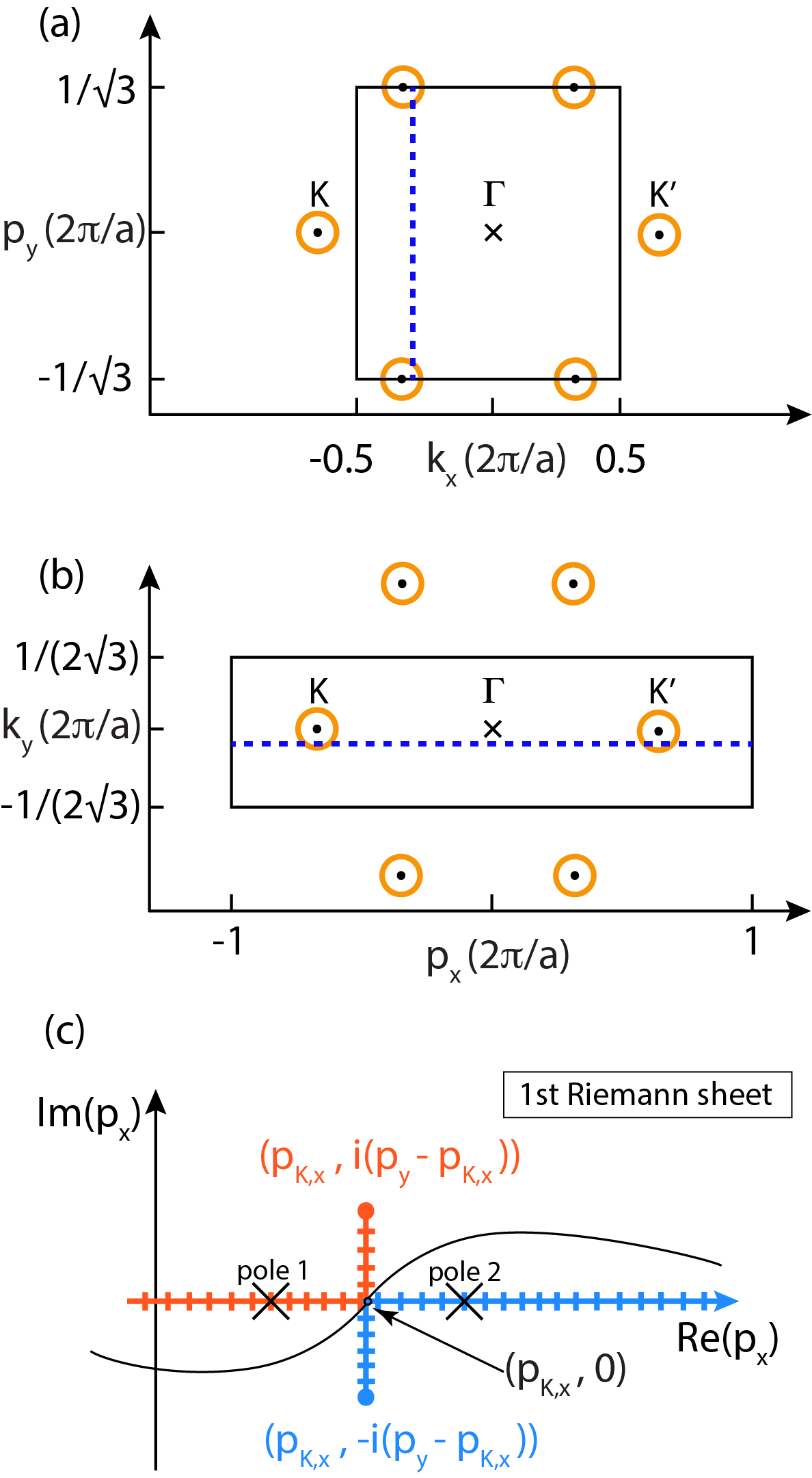
First, note that the integral has a pole when , i.e. when the atomic frequency is resonant with the photonic modes of the lower half of the Dirac cone. While these resonant states occupy a circle in the space, since we are integrating along the axis, there are at most two such singular points along the integration path. These two points are located at
whenever the expression under the square root sign is positive (otherwise there are no poles). These poles in the integrand can be avoided by using an ‘-prescription’. In particular, we introduce a small imaginary term with into the denominator of the integrand to obtain
This prescription makes the integral well-defined and corresponds to the causal Green’s function, which represents the outgoing radiation from a point source Chew (1999). The relevant integration path (that is equivalent to the -prescription via a contour deformation) is indicated in Fig. S5(c). Note that for the integrand has no poles. However, we may use the same -prescription prescription for simplicity.
Furthermore, it is also necessary to choose the appropriate branch when taking the square root to find . The square root function (with a quadratic function as its argument) introduces two branch cuts that emanate from two branch points at , as shown in see Fig. S5(c). Causality of the Green’s function requires that we follow the -prescription path on the first Riemann sheet Chew (1999). Doing so corresponds to enforcing
and
Note that the two branch cuts come infinitesimally close at , which makes this point ill-defined. Therefore, it is essential to break the integration contour into separate paths, such that the first path ends at , whereas the second one starts from there.
In addition, we also need to ensure that the appropriate branches are chosen when evaluating the inverse tangent function to obtain . In particular, we need to ensure that .
With these prescriptions, the integral can be numerically evaluated (see Fig. S5(b) for the relevant integration limits). Analogous prescriptions apply to . Then, substituting Eq. (S30) into Eq. (S29), we can diagonalize the matrix in Eq. (S24) for any inside the 1D irreducible Brillouin zone, yielding eigenvalues for each .
Finally, we note that the calculation for the other stripe orientation can be performed analogously, where the only difference is that the integration is performed along the axis with different limits and the and points are located at the edges of the integration interval (see Fig. S5(a)).
V Analysis of edge states in the presence of free-space decay
In the Main Text, we analyzed the topological edges states when emission to free space modes is neglected. Here, we discuss the effect of free-space emission on the decay rate of edge states.
Before proceeding, we note that standard high-performance calculations for the eigenmodes of photonic crystals, which are based on the plane-wave expansion method to numerically solve Maxwell’s equations Johnson and Joannopoulos (2001), do not accurately account for the coupling of non-guided modes to free-space photons within the light cone. While there exist techniques for numerically obtaining the out-of-plane decay rate of such modes based on finite-difference time-domain calculations Fan and Joannopoulos (2002), doing such calculations at a massive scale would require prohibitively large amounts of computational resources. Therefore, here we utilize prior results from Refs. Perczel et al. (2017b, a) on the decay rates of edge states, arising from cooperative atomic behavior, to analyze the edge states of our system in the presence of free-space decay. In particular, we will make use of the observation that edge modes inside the free-space light cone can decay out of plane at a decay rate comparable to the individual free-space linewidth of the atoms , whereas modes outside the light cone cannot couple to free-space photons due to momentum mismatch Perczel et al. (2017b, a).
The edge states for the two different stripe orientations are illustrated in detail in Fig. S6, where a small detuning of THz was used to analyze the edge states for a large gap of . The properties of the edge states for the two different stripe orientations can be understood by considering the 2D Brillouin zone in momentum space and its projection onto the and axes as shown in Fig. S6(a), (b) and (c) (note that we would obtain one of these two types of edge terminations when projecting along any of the 5 other edges or vertices of the 2D Brillouin zone). The light cone region with is shown in green and the modes of the photonic Dirac cone that are resonant with are marked with yellow circles. Edge states arise only near the Dirac cones (which are the sources of topology in our system). While the projection of the light cone covers the entire 1D Brillouin zone on the axis, it only covers the central part on the axis. Furthermore, while the two inequivalent Dirac cones project to the center of the Brillouin zone on the axis, on the axis they project outside the light cone.
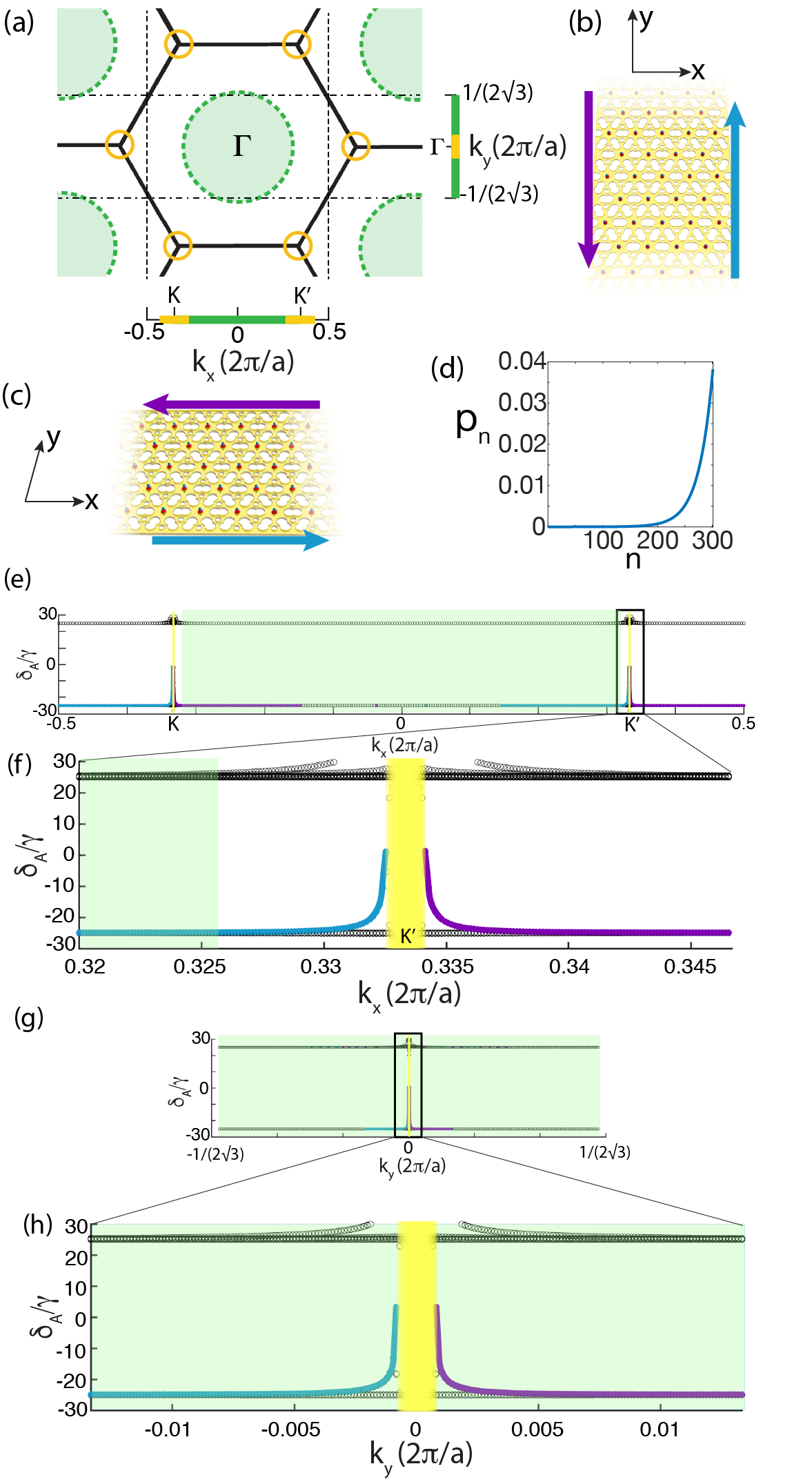
Fig. S6(d) shows the localization of a typical edge states near the boundary. Fig. S6(e) shows the edge states on the -axis. Edge states on the top boundary of the strip are colored purple, whereas edge states on the bottom boundary are colored blue. The part of the Brillouin zone that falls inside the light cone () is shaded green. Modes that fall outside the light cone () cannot couple to free-space modes due to the momentum mismatch (note that in the momentum basis), making these modes long-lived Perczel et al. (2017b, a). In contrast, modes inside the light cone can couple to free-space photons and, therefore, their decay rate is on the order of Perczel et al. (2017b, a). The edge states have non-negligible dispersion only in the immediate vicinity of the and points. Fig. S6(f) provides a zoomed-in view of the edge modes near the point. Inside the yellow region, atomic bands overlap with guided modes of the Dirac cone with the same energy and momentum, and coupling to these modes effectively dissolves the atomic bands (their broadening exceeds the gap size). Fig. S6(f) also shows that the edge states traverse the lower half of the gap outside the light cone and only cross into the yellow region near the center of the gap. Therefore, the edge states in the lower half of the gap are long-lived Perczel et al. (2017b).
Figs. S6(g) and (h) show the edge states on the axis. The edge states have non-negligible dispersion only near the and points, which are both projected to the center of the Brillouin zone for this geometry. Thus all edge modes fall inside the light cone and have an out-of-plane decay rate of approximately .
Crucially, for these parameters the edge states traverse an energy interval of over a momentum interval of , leading to a large group velocity of . Therefore, making the conservative assumption that , an excitation would hop 2000 sites before decaying into far-field photons even if carried by edge modes that can decay to free-space photons.
In general, as is decreased to increase the gap size , the group velocity of the edge states increases as . To understand this scaling, note that , where and are the energy and momentum intervals traversed by the edge states inside the Brillouin zone. Since and (from ), we obtain .
These considerations show that in order to obtain long-lived topological edge states in our system, the lattice edges should be terminated as shown in Fig. S6(c). For such an edge termination, long-lived edge states can be excited, where losses arise only from finite-size effects, such as corners, and imperfections in the periodic lattice Perczel et al. (2017b). The key strategy for ensuring that excitations propagate a significant distance, even in the presence of corners and defects, is to maximize the group velocity of the edge states by increasing the gap size. Thus, lossy regions, where decay occurs on a time scale, will be traversed quickly by the excitation, leading to negligible emission Perczel et al. (2017b).
Recall, however, that obtaining a large energy gap requires to be small, which leads to a small density of states. Thus, a large system is needed to ensure that there are a sufficient number of edge modes in the gap to enable the dispersive propagation of the excitations on the boundaries. Given the limits on system sizes that can be readily simulated with state-of-the-art computational resources, in the Main Text (Figs. 4 and 5) we focused on systems with a large detuning and small band gap, and ignored emission into free-space modes. However, as the preceding analysis shows (see also Ref. Perczel et al. (2017b)), the inclusion of emission into free space does not significantly change the results as long as .
References
- Perczel et al. (2017a) J. Perczel, J. Borregaard, D. E. Chang, H. Pichler, S. F. Yelin, P. Zoller, and M. D. Lukin, Physical Review A 96, 063801 (2017a).
- Bernevig and Hughes (2013) B. A. Bernevig and T. L. Hughes, Topological Insulators and Topological Superconductors (Princeton University Press., 2013).
- Perczel et al. (2018) J. Perczel, P. Kómár, and M. D. Lukin, Physical Review A 98, 033803 (2018).
- Joannopoulos et al. (2008) J. D. Joannopoulos, S. G. Johnson, J. N. Winn, and R. D. Meade, Photonic Crystals: Molding the Flow of Light (Second Edition). (Princeton University Press, 2008) p. 446.
- Glauber and Lewenstein (1991) R. J. Glauber and M. Lewenstein, Physical Review A 43, 467 (1991).
- Johnson and Joannopoulos (2001) S. Johnson and J. Joannopoulos, Optics Express 8, 173 (2001).
-
Note (1)
S. G. Johnson, Official MPB Documentation (online),
https://mpb.readthedocs.io/en/latest/
Scheme_User_Interface/#field-normalization. - Perczel and Lukin (2018) J. Perczel and M. D. Lukin, (2018), arXiv:1810.12815 .
- Peter et al. (2015) D. Peter, N. Y. Yao, N. Lang, S. D. Huber, M. D. Lukin, and H. P. Büchler, Physical Review A 91, 053617 (2015).
- Karzig et al. (2015) T. Karzig, C.-E. Bardyn, N. H. Lindner, and G. Refael, Physical Review X 5, 031001 (2015).
- Bettles et al. (2017) R. J. Bettles, J. Minář, C. S. Adams, I. Lesanovsky, and B. Olmos, Physical Review A 96, 041603 (2017).
- Gross and Haroche (1982) M. Gross and S. Haroche, Physics Reports 93, 301 (1982).
- González-Tudela and Cirac (2018) A. González-Tudela and J. I. Cirac, Physical Review A 97, 043831 (2018).
- Chew (1999) W. C. Chew, Wave and fields in inhomogeneous media (IEEE, 1999).
- Fan and Joannopoulos (2002) S. Fan and J. D. Joannopoulos, Physical Review B 65, 235112 (2002).
- Perczel et al. (2017b) J. Perczel, J. Borregaard, D. Chang, H. Pichler, S. Yelin, P. Zoller, and M. Lukin, Physical Review Letters 119, 023603 (2017b).