Coherent Terahertz synchrotron radiation mastered by controlling the irregular dynamics of relativistic electron bunches
Spontaneous formation of spatial structures (patterns) occurs in various contexts, ranging from sand dunes charru2013sand and rogue wave formation hopkin2004sea ; solli2007optical , to traffic jams helbing2001traffic . These last decades, very practical reasons also led to studies of pattern formation in relativistic electron bunches used in synchrotron radiation light sources. As the main motivation, the patterns which spontaneously appear during an instability increase the terahertz radiation power by factors exceeding 10000 abo2002.PhysRevLett.88.254801 ; byrd2002.PhysRevLett.89.224801 . However the irregularity of these patterns byrd2002.PhysRevLett.89.224801 ; venturini2002.PhysRevLett.89.224802 ; abo2002.PhysRevLett.88.254801 ; uvsor_MBI_ybco ; roussel2015.EOS ; brosi2016fast ; PhysRevAccelBeams.19.020704 largely prevented applications of this powerful source. Here we show how to make the spatio-temporal patterns regular (and thus the emitted THz power) using a point of view borrowed from chaos control theory ott1990controlling ; shinbrot1993using ; pyragas1992continuous . Mathematically, regular unstable solutions are expected to coexist with the undesired irregular solutions, and may thus be controllable using feedback control. We demonstrate the stabilization of such regular solutions in the Synchrotron SOLEIL storage ring. Operation of these “controlled unstable solutions” enables new designs of high charge and stable synchrotron radiation sources.
Synchrotron light sources are used worldwide to produce brilliant light from THz to hard X-rays, allowing to investigate a very large range of matter properties. In these sources where electron bunches travel at relativistic velocities, an ubiquitous phenomenon occurs when the bunch charge density exceeds a threshold value. Due to the interaction between the electron bunch and its own emitted electric field, micro-structures spontaneously appear in the longitudinal profile (and phase-space) of the bunch stupakov2002.PhysRevSTAB.5.054402 ; venturini2002.PhysRevLett.89.224802 ; sannibale2004.PhysRevLett.93.094801 ; Warnock:2006qa (see Fig. 1(a) and (b) for the SOLEIL storage ring which will be considered here). In storage rings, these structures are responsible for a huge emission of coherent light in the terahertz range, typically times normal synchrotron radiation power density. However, as the micro-structures appear mostly in the form of bursts [Fig. 1(d)] this type of source is barely usable in user applications. Hence, research in this domain has naturally attempted to find regions for which coherent emission (CSR) occurs while bursting dynamics is absent. Such ”parameter search” methods succeeded in identifying parameter regions with stable coherent emission. However, this corresponds to special configurations (with short and low charge electron bunches, in the so-called low-alpha operation abo2002.PhysRevLett.88.254801 ; byrd2002.PhysRevLett.89.224801 ; shimada2009transverse ; feikes2011metrology ; martin2011experience ; roy.RSI.84.033102.2013 ; PhysRevAccelBeams.19.020704 ; brosi2016fast ; tammaro2015high ; steinmann2016frequency ) which are not compatible with most of the user experiments. Therefore, this type of THz source is used in relatively few synchrotron radiation facilities (SOLEIL, DIAMOND, BESSY-II), and only during a small part of the year.
”Parameter search approaches” are however not the only possibilities for avoiding instabilities. The point of view that we will use here is directly borrowed from the so-called chaos control theory, introduced by Ott, Grebogi and Yorke (OGY) ott1990controlling ; shinbrot1993using . Mathematically, when an undesired irregular solution is observed – bursts of microbunching in our specific case – other unstable solutions usually coexist. The existence of these unstable solutions is often viewed as mathematical curiosities. However, OGY pointed out two properties with far-reaching applications. First these co-existing unstable solutions are generically controllable, i.e., there exists feedback loops between an observable and available parameters, that can force the system to stay onto the unstable solution. Furthermore, as the feedback stabilizes an already existing solution, the extra-power required for stabilization is theoretically infinitesimally small (it is only limited by imperfections or noise, see Refs. shinbrot1993using ; boccaletti2000control for details). These two points make the OGY strategy a good candidate for the control of high power systems, like synchrotron radiation facilities.
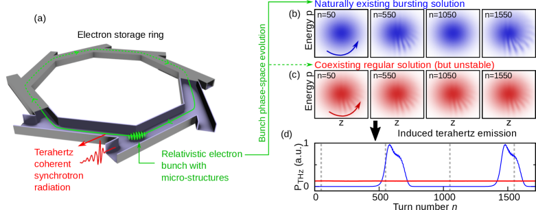
In this Letter, we show that it is possible to suppress the bursts of microbunching instabilities occurring in storage-ring synchrotron radiation facilities, using this strategy inspired from chaos control. We will demonstrate that, although the acceleration powers used in synchrotron radiation facilities are in the fraction-of-MegaWatt range, tiny actions on a control parameter are sufficient to maintain the system on an unstable regular solution of phase-space, as the one displayed in Fig. 1c.
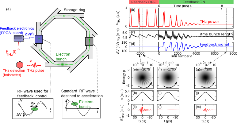
The experimental design of the feedback loop, and simulated expected performances are summarized in Figure 2. A fast bolometer (with 1 s response time) measures the power fluctuations of the emitted coherent THz radiation. This signal is used for calculating a control signal , using a Field-Programmable Gate Array (FPGA). The control signal is then directly applied onto one of the four accelerating cavities of the storage ring (see Figure 2a and Methods for details). As detailed after, the action on the RF cavity signal is to modify the bunch length, which is directly linked to the bursting behaviour (see Fig. 2c for ). In this first study, the feasibility of control is tested using only elementary feedback loops, and in particular we have performed a systematic study using the so-called Pyragas method, which has proven to be efficient for stabilizing various non-accelerator systems boccaletti2000control ; Ahlborn2004 . In numerical simulations and then with the FPGA used in the experiment, we compute the following signal :
| (1) | |||
| (2) |
where is the signal detected by the bolometer, at the THz and infrared AILES beamline roy.IPT.49.139.2006 . Equation (1) represents a low-pass filter with a time constant . Equation (2) represents the Pyragas feedback, which involves two parameters (gain) and (delay). corresponds to the voltage amplitude applied to the accelerating cavity of the storage ring. The cutoff frequency of the low-pass filter is 3 kHz, i.e., slightly lower that the bandwidth of the high power RF system (10 kHz). This filter removes components at the revolution frequency (845 kHz), as well as the frequency due to the rotation of the microstructures in phase-space evain2017direct , in the 80 kHz range here. In order to find the conditions for stabilization, the feedback parameters and have been systematically scanned, while monitoring the remaining fluctuations of the THz power (both in the numerical design study, and in the experiment).
A typical numerical simulation result is displayed in Figures 2(b-m) (see Methods for numerical details). Figure 2(b) represents a transient that occurs when the feedback is applied, showing that the bursts of terahertz power are expected to be suppressed. However the microstructure pattern still exists in phase-space (see Fig. 2g), leading to a regular emission of coherent terahertz radiation. Moreover, we can see that the feedback signal tends to extremely small values after the transient has died out (Fig. 2d). This is a consequence of the fact that we are stabilizing an already existing periodic state of the system.
Numerical simulations also showed that efficient control is expected when the control voltage amplitude acts on the slope of the accelerating field. Thus increasing should only ”compress” the bunch and vice-versa (see left insets of Fig. 2). However, a direct variation of the RF signal amplitude will also accelerate or decelerate the bunch (more precisely the so-called synchronous electron sannibale2004.PhysRevLett.93.094801 ). This is a key point in the realization of an efficient feedback control, and it led us to design the experiment so that the feedback signal is applied in an accelerating cavity operating in the so-called ”zero-crossing” situation (see Methods).
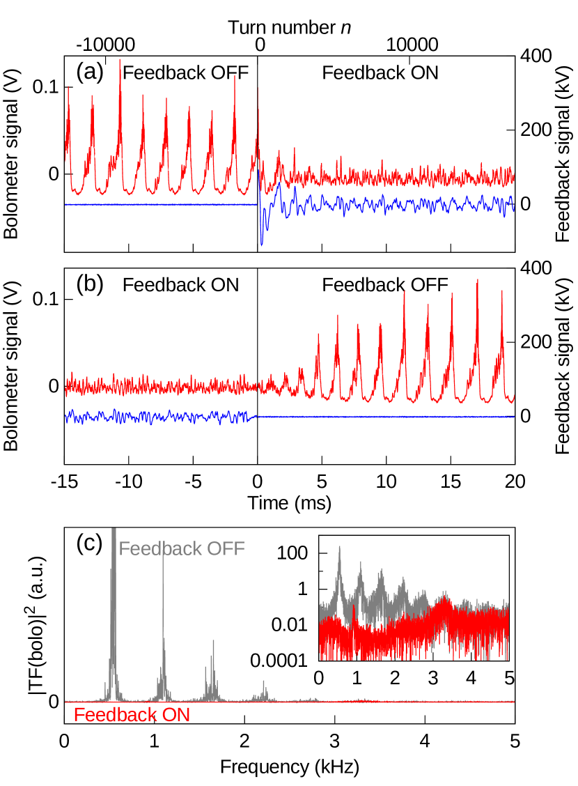
We have tested experimentally this feedback scheme at the SOLEIL synchrotron radiation facility (Figure 3). During the experiments, our storage ring was operated as for normal user operation, at an energy of 2.75 GeV (see Methods for parameters). We stored a single high charge electron bunch ( mA) in order to exceed the microbunching instability threshold (at about 8.7 mA), and obtain strong bursts of coherent THz emission. In each feedback control experiment, we started by testing the control efficiency versus parameters and in ranges that are suggested by numerical results. Automatic scans provided optimal values of and in typically 15 minutes. Typical feedback control results are represented in Figure 3. Figures 3(a) and 3(b) display the transient obtained when the feedback control is suddenly switched ON and OFF respectively. The Fourier spectra of the controlled and uncontrolled signals (Fig. 3c) show that the main spectral components of fluctuations are suppressed until more than 40 dB (for the feedback efficiency versus frequency, see the figure in the supplementary material).
Quantitative analysis of the remaining control fluctuations also provide important information on the required RF amplitude that is necessary to maintain succesfull control of the unstable regular state (the remaining fluctuation visible in Fig. 3). Quantitatively, the fluctuations of the RF signal amplitude is about of 8 kV RMS (over the 10 kHz bandwidth of the power RF system). This value represents a variation of only 0.3% of the total RF signal slope seen by the electrons.
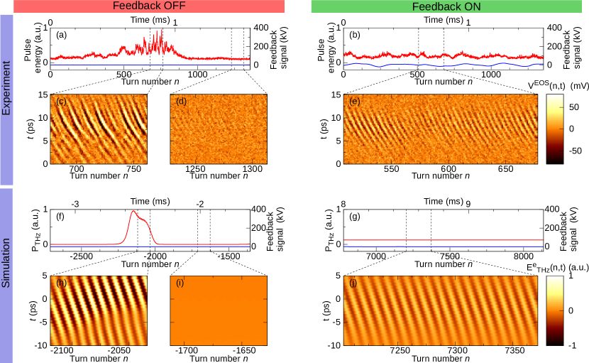
In a third step we have performed an experiment to observe directly the spatio-temporal evolution of the electron-bunch structures in the controlled and uncontrolled cases. For this purpose, we have used a single-shot electro-optic sampling system based on photonic time-stretch, which is described elsewhere szwaj2016high . This system enables to record in a single-shot mode the electric field of the THz pulses (envelope and carrier), at each storage ring turn. Figure 4 shows the turn-by-turn evolution of the THz pulses with and without feedback. As in the simulations, without feedback there is an alternance of quiet periods (without micro-structures) and irregular terahertz radiation. With feedback, the micro-structures appear almost always present and form a regular pattern, i.e. they appear periodically at the tail of the bunch and drift at constant velocity toward the head (due to the rotation of the bunch in the phase-space). Hence, the feedback not only removes the bursting behavior, but also make the micro-structures appear and propagate regularly in the bunch.
In conclusion, we reveal the existence of a regular, but unstable, dynamical state of high-charge electron-bunches circulating in a storage ring, and we demonstrate the possibility of stabilizing this state thanks to a low power feedback loop. As a consequence of this method (inspired by chaos of control theory), a modification of less than 0.3% in the system parameters permits to decrease by more than 40 dB the THz fluctuations at the synchrotron SOLEIL (while keeping the coherent emission). A foreseen application concerns the production of a stable coherent THz synchrotron radiation (CSR) in more synchrotron radiation facilities in the world, and/or during a large fraction of the year (for instance at SOLEIL). Moreover, it is important to note that the simple feedback scheme used here was destined to a proof-of-principle experiment, and that more efficient feedback control schemes probably remain to be discovered. Current open questions concern the possibility to achieve control at very high current and/or when the instability is characterized by many unstable eigenvalues (i.e., where Pyragas control is observed to fail). These next steps are expected to require cross-disciplinary works between the fields of accelerator physics, and nonlinear dynamics of spatially extended systems.
Methods
Storage ring
The SOLEIL storage ring is operated in single-bunch mode, at 2.75 GeV, in the so-called ”nominal-alpha mode”, i.e., with a momentum compaction factor . Four superconducting cavities are fed by power RF sources at 352.2 MHz (i.e., the 416th harmonic of the revolution frequency). Three cavities are used for normal acceleration at each turn, with an accelerating voltage amplitude of 800 kV. The fourth cavity is driven by the feedback system (see below).
Furthermore, the storage ring is operated in the so-called top-up mode, consisting in periodically injecting electrons for compensating the natural losses in the ring. This mode was a crucial point as it allowed systematic studies (as finding the optimal parameters), without change of the storage ring current.
Numerical simulations
Numerical simulations are performed by using the one-dimensional Vlasov-Fokker-Planck model of storage rings Warnock:2006qa , which is known to reproduce the microbunching instability schonfeldt2017parallelized ; roussel2015.EOS . The longitudinal electron bunch dynamics with feedback is modeled by the equation:
| (3) | |||||
| (4) |
where is the normalized longitudinal position ( with the longitudinal coordinate and the equilibrium RMS bunch length without collective effect), the normalized longitudinal energy ( with the electron energy in eV, the storage ring nominal energy and the energy spread at equilibrium, without collective effect). is the normalized time , with the time and the synchrotron frequency. , where is the synchrotron damping time. The interactions between electrons are modeled in the term , where the standard parallel plate model (with a radius and a distance between the plates of ) is used (see evain2017direct for more details). is the normalized bunch current, , with is the average beam current, the dipole radius of curvature, and the revolution period, the electron charge. All parameters are in MKS units. As in the experiment, the feedback is:
| (5) | |||
| (6) |
With the low-pass filter value, the feedback gain, the feedback delay and the emitted THz power ( with the Fourier transform of the charge density and represent the bolometer detection cutoff).
As in the experiment, we put a limitation on the maximum value of .
The Vlasov-Fokker Planck equation is integrated using the Warnock scheme Warnock:2006qa , that we have implemented as a parallel code (in MPI).
The parameters used in the article (synchrotron SOLEIL and feedback parameters) are : GeV, mm, , kHz, ms, m, s, cm, mA, , , (0.2 ms in non normalized units), (3 kHz in non normalized units), and kV.
Feedback control system: detection and low power electronics
The THz signal is monitored by an InSb hot electron bolometer (Infrared Laboratories), with s response time, and AC output coupling. The bolometer detects the Terahertz Coherent Synchrotron Radiation emitted at the AILES beamline of synchrotron SOLEIL. The bolometer signal is then digitized and processed using a low-cost Field-Programmable Gate Array (FPGA) board (Red Pitaya STEMlab 125-14 board, based on the Xilinx Zynq 7010 SOC-FPGA). The digitization is performed by one of the two ADCs of the FPGA board at 125 MS/s, with a 50 MHz bandwidth. The acquired signal is first digitally low-pass filtered using a first order filter (with a cutoff frequency kHz), and resampled at 1 MS/s. The FPGA uses this filtered signal to compute the feedback signal . This digital signal is then converted to an analog signal, using one of the two DACs of the FPGA board.
In addition, the bolometer and control signals are also monitored using a 1 GHz oscilloscope (Lecroy WR104MXI). The bolometer, oscilloscope, FPGA (and its control computer) are placed in the AILES beamline area, and the analog control signal provided by the FPGA is transported to the low-level RF (LLRF) system of SOLEIL located at few tens of meters from the FPGA, using a coaxial cable. This signal is used to modulate the amplitude of one of the RF accelerating cavities.
Feedback control system: high power part
At SOLEIL, four accelerating cavities are usually fed with 352.2 MHz power RF. For this feedback control experiment, one of the four cavities has been operated in the so-called ”zero-crossing” mode, i.e., the phase of the electric field is adjusted so that the field is zero for the synchronous particle at each electron bunch passage as displayed in Fig. 2. In absence of feedback, the cavity voltage amplitude is 700 kV. The control signal delivered by the FPGA is limited to V, which corresponds to an RF amplitude modification of kV. The bandwidth of this amplitude modulation has been measured to be 10 KHz.
Feedback control system: protection against accidental beam loss
While searching for optimum feedback parameters and , some parameter sets have destabilizing effect, leading in some cases to beam loss. In order to avoid this issue, we also added an interlock system, that disables the feedback loop when the electron bunch transverse position (monitored by a beam position monitor) departs the nominal orbit by a threshold value. This value has been adjusted empirically (by trial-and-error) to m. Operation of this interlock was an important component, as it allowed us to freely scan feedback parameters and find the optimal ones, without needing to take care of possible electron beam loss issues.
Single-shot recording of the terahertz CSR pulses
The data displayed in Figure 4 (emitted THz pulse shapes at each turn) have been recorded using a single-shot electro-optic sampling system. The setup, which is detailed in Refs. szwaj2016high ; evain2017direct , uses a single-shot electro-optic sampling using chirped laser pulses, combined with photonic time-stretch mahjoubfar2017time for enabling high repetition rate recording.
Data availability
The data that support the findings of this study are available from the corresponding author upon reasonable request.
Author contributions
S.B. and C.E. carried out the numerical simulations. C.E., S.B. and C.S. led the experimental realization. C.E., S.B. and J.R. developed the FPGA software. Experiments at SOLEIL designed and performed by M.-A.T. (ring configuration and operation), F.R. (RF system configuration and seetings), M. Labat and N. Hubert (interlock and diagnostic systems), J.-B. B. and P. Roy (AILES beamline), M.L.-P., E.R., S.B.,C.E, C.S. (Electro-Optics-Sampling detection system and feedback system). Experimental data analysed by C.S. and C.E. All the authors participate to the redaction.
Acknowledgments
This work has been partially supported by the LABEX CEMPI (ANR-11-LABX-0007) and the Equipex Flux (ANR-11-EQPX-0017), as well as by the Ministry of Higher Education and Research, Hauts de France council and European Regional Development Fund (ERDF) through the Contrat de Projets Etat-Region (CPER Photonics for Society P4S). The project used HPC resources from GENCI TGCC/IDRIS (i2016057057,A0040507057).
References
- (1) Charru, F., Andreotti, B. & Claudin, P. Sand ripples and dunes. Annual Review of Fluid Mechanics 45, 469–493 (2013).
- (2) Hopkin, M. Sea snapshots will map frequency of freak waves. Nature (2004).
- (3) Solli, D., Ropers, C., Koonath, P. & Jalali, B. Optical rogue waves. Nature 450, 1054 (2007).
- (4) Helbing, D. Traffic and related self-driven many-particle systems. Reviews of modern physics 73, 1067 (2001).
- (5) Abo-Bakr, M., Feikes, J., Holldack, K., Wüstefeld, G. & Hübers, H.-W. Steady-state far-infrared coherent synchrotron radiation detected at BESSY II. Phys. Rev. Lett. 88, 254801 (2002).
- (6) Byrd, J. M. et al. Observation of broadband self-amplified spontaneous coherent terahertz synchrotron radiation in a storage ring. Phys. Rev. Lett. 89, 224801 (2002).
- (7) Venturini, M. & Warnock, R. Bursts of coherent synchrotron radiation in electron storage rings: A dynamical model. Phys. Rev. Lett. 89, 224802 (2002).
- (8) Roussel, E. et al. Microbunching instability in relativistic electron bunches: Direct observations of the microstructures using ultrafast YBCO detectors. Phys. Rev. Lett. 113, 094801 (2014).
- (9) Roussel, E. et al. Observing microscopic structures of a relativistic object using a time-stretch strategy. Scientific Reports 5 (2015).
- (10) Brosi, M. et al. Fast mapping of terahertz bursting thresholds and characteristics at synchrotron light sources. Physical Review Accelerators and Beams 19, 110701 (2016).
- (11) Billinghurst, B. E. et al. Longitudinal bunch dynamics study with coherent synchrotron radiation. Phys. Rev. Accel. Beams 19, 020704 (2016).
- (12) Ott, E., Grebogi, C. & Yorke, J. A. Controlling chaos. Physical review letters 64, 1196 (1990).
- (13) Shinbrot, T., Grebogi, C., Yorke, J. A. & Ott, E. Using small perturbations to control chaos. nature 363, 411 (1993).
- (14) Pyragas, K. Continuous control of chaos by self-controlling feedback. Physics letters A 170, 421–428 (1992).
- (15) Stupakov, G. & Heifets, S. Beam instability and microbunching due to coherent synchrotron radiation. Phys. Rev. ST Accel. Beams 5, 054402 (2002).
- (16) Sannibale, F. et al. A model describing stable coherent synchrotron radiation in storage rings. Phys. Rev. Lett. 93, 094801 (2004).
- (17) Warnock, R. L. Study of bunch instabilities by the nonlinear Vlasov-Fokker-Planck equation. Nucl. Instrum. Meth. Phys. Res., Sect. A 561, 186–194 (2006).
- (18) Shimada, M. et al. Transverse-longitudinal coupling effect in laser bunch slicing. Physical review letters 103, 144802 (2009).
- (19) Feikes, J. et al. Metrology light source: The first electron storage ring optimized for generating coherent thz radiation. Physical Review Special Topics-Accelerators and Beams 14, 030705 (2011).
- (20) Martin, I., Rehm, G., Thomas, C. & Bartolini, R. Experience with low-alpha lattices at the diamond light source. Physical Review Special Topics-Accelerators and Beams 14, 040705 (2011).
- (21) Barros, J. et al. Coherent synchrotron radiation for broadband terahertz spectroscopy. Review of Scientific Instruments 84, 033102 (2013).
- (22) Tammaro, S. et al. High density terahertz frequency comb produced by coherent synchrotron radiation. Nature communications 6 (2015).
- (23) Steinmann, J. L. et al. Frequency-comb spectrum of periodic-patterned signals. Physical review letters 117, 174802 (2016).
- (24) Boccaletti, S., Grebogi, C., Lai, Y.-C., Mancini, H. & Maza, D. The control of chaos: theory and applications. Physics reports 329, 103–197 (2000).
- (25) Ahlborn, A. & Parlitz, U. Stabilizing unstable steady states using multiple delay feedback control. Phys. Rev. Lett. 93, 264101 (2004).
- (26) Roy, P., Rouzières, M., Qi, Z. & Chubar, O. The ailes infrared beamline on the third generation synchrotron radiation facility soleil. Infrared Physics and Technology 49, 139 (2006).
- (27) Evain, C. et al. Direct observation of spatiotemporal dynamics of short electron bunches in storage rings. Physical Review Letters 118, 054801 (2017).
- (28) Szwaj, C. et al. High sensitivity photonic time-stretch electro-optic sampling of terahertz pulses. Review of Scientific Instruments 87, 103111 (2016).
- (29) Schönfeldt, P., Brosi, M., Schwarz, M., Steinmann, J. L. & Müller, A.-S. Parallelized vlasov-fokker-planck solver for desktop personal computers. Physical Review Accelerators and Beams 20, 030704 (2017).
- (30) Mahjoubfar, A. et al. Time stretch and its applications. Nature Photonics 11, 341–351 (2017).