Electrostatic deflections of cantilevered semiconducting single-walled carbon nanotubes
Abstract
How carbon nanotubes behave in an external electric field? What will be the relation between the intensity of the electric field and the tube’s deformation? What are the geometry effects on the response of carbon nanotubes to electric fields? To answer these questions, we have developed a new combined computational technique to study electrostatic field induced deformations of carbon nanotubes. In this work, we find that the deflection angle of cantilevered semiconducting single-walled carbon nanotubes is proportional to the square of the electric field strength, and the tubes can be most bent when the field angle ranges from to degrees. Furthermore, the deflection angle is also found to be proportional to the aspect ratio . Our results provide a good qualitative agreement with those of one previous experimental study.
pacs:
73.63.Fg, 77.22.Ej, 31.15.-p, 77.55.+fI Introduction
Carbon nanotubes (CNTs) can be ideal building blocks for nanoelectromechanical systems (NEMS) due to their unique electrical and mechanical properties Saito et al. (1998). Thus, they have attracted much interest from both technical and scientific communities concerned with sensing, actuation, vibration and lab-on-a-chip applications Ke and Espinosa (2005). Cantilevered semiconducting CNTs can be used as key elements in NEMS such as nanotweezers Akita et al. (2001) and nanorelays Kinaret et al. (2003). Their electric field induced deformation is a key character for these promising applications, as well as their fabrication Li et al. (2004), separation Krupke et al. (2003) and electromanipulation Hertel et al. (1998).
In a previous study, Poncharal et al Poncharal et al. (1999) reported the electric deflections of cantilevered multiwalled CNTs observed using a transmission electron microscope. Electrostrictions in single-walled CNTs (SWCNTs) were observed by El-Hami and Matsushige El-Hami and Matsushige (2005) using an atomic force microscopy (AFM). Q.-L. Bao et al Bao et al. (2006) reported that the microstructure of CNTs can be changed by an electric field during growth using a high-resolution transmission electron microscope. Y.-F. Guo and W.-L. Guo Guo and Guo (2003a) carried out quantum mechanics calculations to investigate the electric field induced tensile breaking and the influence of external field on the tensile stiffness of CNTs, and found that both the tensile stiffness and the strength of CNTs decrease with increasing intensity of electric field. Torrens Torrens (2004) reported that the polarizabilities of CNTs can be modified reversibly by external radial deformation. Mayer and Lambin Mayer and Lambin (2005) calculated the electrostatic forces acting on CNTs placed in the vicinity of metallic protrusions for dielectrophoresis. W. Guo and Y. Guo Guo and Guo (2003b) found giant electrostrictive deformations in SWCNTs using quantum mechanics simulations.
The calculations using traditional first-principle methods are very time-consuming, so that the size of the systems considered is always very limited in past theoretical studies concerning the effects of external field. That is one of the main reasons why deformations of CNTs in electric fields and their geometric effects are still not fully understood up to date.
How CNTs behave in an external electric field? What will be the relation between the intensity of the electric field and the tube’s deformation? What are the geometry effects on the response of CNTs to electric fields? To answer these questions, we have developed a new combined computational technique to study electrostatic field induced deformations. In this technique the interatomic potential is described in an empirical way and the electrostatic interaction is calculated using a Gaussian renormalized point dipole interaction model (e.g. interactions between broaden dipoles). The main advantage of this method is its ability to deal with much larger systems with a reasonable computational requirement. This enabled us to carry out a series of simulations to study the induced deformations of various carbon structures in electrostatic fields.
In this work, we study the electrostatic deflections of cantilevered semiconducting SWCNTs in a non-axial homogeneous field. This study addresses the relation between the external field, the mechanical resistance of SWCNTs and their electrostatic polarizabilities. In the last few years, the polarizability of CNTs has been intensively investigated Benedict et al. (1995); Mayer (2005a, b); Guo et al. (2004); Kozinsky and Marzari (2006); Novikov and Levitov (2006). For example, it is known that the static polarizabilities of CNTs are very anisotropic, and that the polarizabilities are proportional to the radius square in the plane perpendicular to the tube axis and almost independent of chirality. In this study we use Gaussian regularized propagators Langlet et al. (2004), Langlet et al. (2006) to calculate the local polarizability of carbon atoms. In this model, the standard vacuum propagator is convoluted by a Gaussian function, in order to avoid polarization catastrophes. This is the same as considering that the dipoles are not real point dipoles but rather due to Gaussian distribution of charges whose width is related to the polarizabilities Mayer et al. (2006),Mayer (2007). Compared to first-principle techniques such as ab initio calculations, the local auto-coherent polarizabilities related to the geometrical structure of carbon atoms can be quickly evaluated in this model. It can therefore be practically used in dynamic simulations for larger systems.
In this work, a simple gradient algorithm is used to calculate equilibrium configurations of the atoms by minimizing the total energy of the systems, which consists of both the interatomic and the induced electrostatic interactions. The interatomic potential is analyzed using an adaptive intermolecular reactive empirical bond-order hydrocarbon (AIREBO) potential function formulated by Stuart et al Stuart et al. (2000). During the simulations, deflections of cantilevered CNTs are recorded dynamically as a function of the iteration step. Examples can be viewed at one of the authors’ personal web page Wan . The theory will be presented in section 2. In section 3, we examine the relations between the deflections and the intensities and orientations of the applied fields, respectively. The effects of tubes chiralities, radii and lengths are also studied. We draw a conclusion at the end of this section.
II Theory
In this study, we examine cantilevered semiconducting SWCNTs submitted to an external homogeneous electrostatic field in free space with zero net charge and zero permanent dipole moment. At the beginning of the simulations, an open-ended tube, fixed at one end, is relaxed. When an electric field is applied, a dipole is induced on each atom. The induced dipole is modeled as an ideal dipole with anisotropic linear polarizabilities. The field intensity is supposed small enough so that any hyperpolarization effect can be neglected. A simple gradient algorithm is used to simulate the deformation of CNTs in the field by minimizing the total energy of the systems . The motionless equilibrium configuration of the atoms corresponds to the minimum value in the energy curve. Classical molecular dynamics is not used in order to avoid the thermal vibration because we consider only the equilibrium stats of tubes in this study. is the sum of two terms: the induced electrostatic energy and the interatomic potential .
| (1) |
In which consists of three terms:
| (2) |
where is the total number of atom, is the dipole induced on atom , represents the electric field created by an other dipole around atom , stands for the external field, is the local anisotropic polarizability tensor of atom adapted from graphite Langlet et al. (2006). In this expression, the first term is the self energy term, the second term accounts for the dipole-dipole interaction, the last term presents the interaction with the external field Mayer et al. (2006). The two basic parameters of the polarizability tensor are taken to be: Å3 and Å3, with and meaning parallel and perpendicular to the plane of graphene sheet, respectively. Note that due to the use of point dipole model, these parameters are not valid for metallic tubes.
The field on atom due to another induced dipole can be written as:
| (3) |
In this equation, describes the local field at atom and the regularized tensor is the double gradient of Green’s generalized function for the Laplace equation, convoluted by a Gaussian distribution to avoid polarizability catastrophes Langlet et al. (2004),Langlet et al. (2006). The distribution of dipoles is determined by the fact that the equilibrium state of the dipole distribution should correspond to the minimum value of . This means that the partial derivatives of the total electrostatic energy with respect to the components of the dipoles should be zero.
| (4) |
Where , , are the three components of the dipole . Putting Eq. 2 and Eq. 3 into Eq. 4 gives a linear system of equations for vectorial variables.
| (5) |
The local fields and the dipole moments can be calculated by solving this system. By putting these expressions for the minimizing back into Eq. 2, cancellation of various terms leaves only a simple expression for the minimum value of as a function of the :
| (6) |
The interatomic potential is determined using the AIREBO potential function Stuart et al. (2000). This potential is an extension of Brenner’s second generation potential Brenner et al. (2002) and includes long-range atomic interactions and single bond torsional interactions. In this type of potential, the total interatomic potential energy is the sum of individual pair interactions containing a many-body bond order function:
| (7) |
where and are the interatomic repulsion and attraction terms between valence electrons, for bound atoms. The bond order function provides the many body effects by depending on the local atomic environment of atoms and . The long-range interactions are included by adding a parameterized Lennard-Jones 12-6 potential term . represents the torsional interactions.
III Results and discussion
In this study, we use Cartesian coordinates with the axis along the principal axis of the tube. The tubes are fixed at one end in an imposed homogeneous electric field. The tube length is in the range of 2.0 to 8.4 nm. In order to get enough measurable deflection of these short SWCNTs, the strength of applied external electric fields is in the range of to V/nm. This is much stronger than the ordinary field reported in the experiments. On the other hand, as going to be discussed in the following parts of this section, the deflection of SWCNTs is proportional to the square of tube length and it is also proportional to the square of field strength. For example, in order to get the same electrostatic deflection for a tube one thousand times longer, it is just enough to apply a field a thousand times smaller. Hence, considering that the lengths of CNTs studied in previous experimental works are in the ranges of some micrometers, the field emission effect caused by strong fields is neglected. Furthermore, we note that the actual external electric field created by the electrodes is usually inhomogeneous in real experiments, however this inhomogeneous distribution varies from one experimental setup to another. For the sake of simplicity, we have therefore chosen to use a homogeneous external field distribution, as in previous theoretical studies.
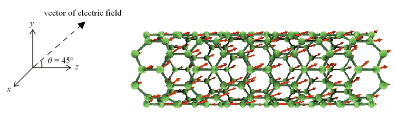
In this work, all applied electric fields are parallel to the plane due to the symmetry of the system. The field angle is defined as the angle between the field direction and the axis. The deflection at the tip of the tube is noted as . We studied at first the relation between the intensity of the external field and the deflection of cantilevered SWCNTs.
When a carbon atom is brought into an electric field, the field tends to shift the electrons and the nuclei in opposite directions. Thus, induced dipoles are created. Fig. 1 shows dipoles induced on atoms by an electrostatic field in a zigzag tube (8,0). It is selected because of its symmetric geometry and small radius.
The positive and negative charges of CNT are brought about a relative displacement due to the electric force. The tube tends to be either parallel (in most cases) by dipole-dipole and dipole-field interactions. Tubes can therefore be bent by induced forces and moments to the field direction. Fig. 2 shows the deflections of a CNT induced by various external electric fields corresponding to various field strength , but a given . Note that these are the equilibrium configurations of the atoms, around which the tubes would vibrate at non-zero temperature Treacy, M. M. J. et al. (2000).
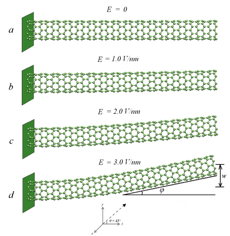
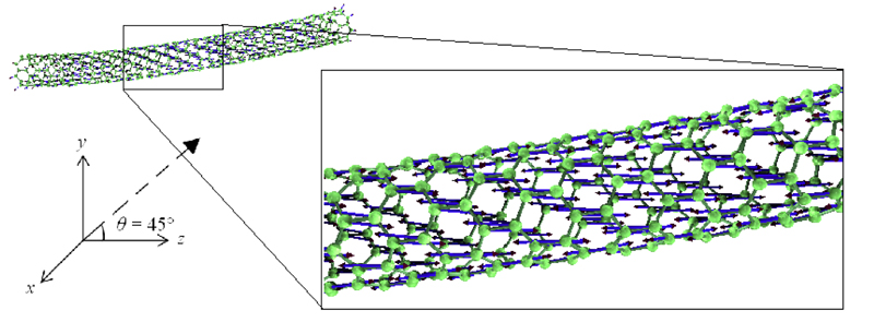
It can be seen that as expected, the tubes are bent toward the direction of the external electric field. Note that the tube is only curved at the part closed to the fix end. The right side part of the tubes remains straight. We compared the atomic structure of this straight part in Fig. 2 (b)-(d) to an unmoved tube as shown in Fig. 2 (a). It is found that the average bond length in this part is slightly smaller than that in the original one. That means the tube is not only bent by induced moments but also compressed by induced forces at the same time, as the electrostriction effects found in Refs. El-Hami and Matsushige, 2005 and Refs. Guo and Guo, 2003b. In fact, the distribution of electrostatic forces acting on the atoms is rather inhomogeneous as shown in Fig. 3 as an example. In consequence, the macroscopic continuum mechanics models of beam structures subjected to simple loadings can not be directly used to calculate internal strains for tubes in an electric field, without incorporating volume densities of torques.
For convenience, we define a deformation angle to describe the deformations of the tubes. It is equal to the angle between the axis and the neutral axis of the deformed CNTs at their free end. The relation between and the intensity of the external field is presented in Fig. 4.
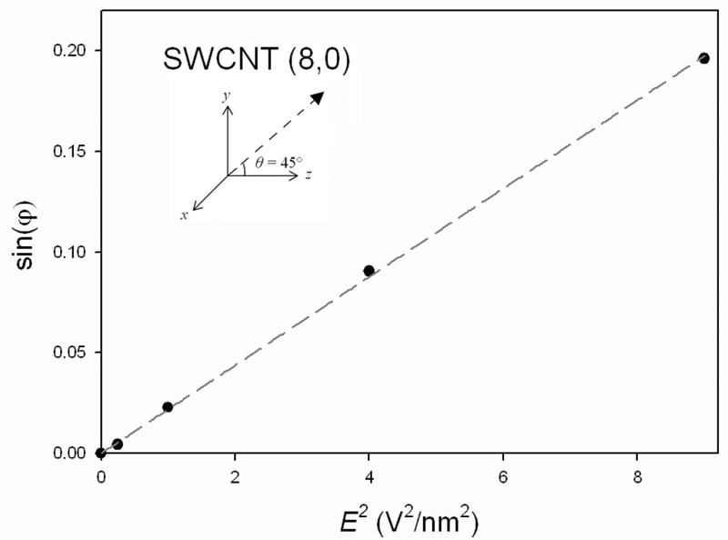
It can be seen that is almost proportional to the square of .
| (8) |
Where for this (8,0) tube with . Note when the value of remains small, one can also find that the deflection at the tip of a long tube is almost proportional to . This provides a good qualitative agreement with the experimental study of Poncharal et al Poncharal et al. (1999).
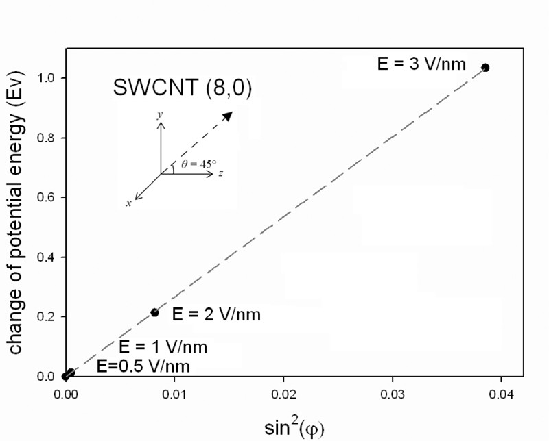
In Fig. 5, we plot the change of the potential versus the square of . It shows that . Furthermore, we find also that the change of the global polarizability in the direction of the incident field is proportional to although the individual components of are not proportional to ( while and remains almost constant). Combined with the fact that is almost proportional to the square of (Eq. 8), this means that we also have , hence .
In a second series of simulations, we studied the influence of the orientation of the external field on the response of CNTs. Fig. 6 presents the relation between for a (8,0) SWCNT and the field angle .
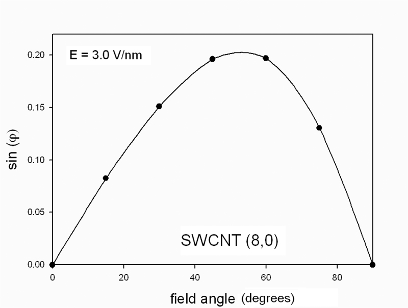
There is no obvious deflection effect found in CNTs when the applied electric field is either parallel or perpendicular to the main tube axis. In a global point of view, this is due to the fact that the induced molecular dipole of the tube is already aligned to the direction of the field in these two cases. That means the induced torque acting on the molecule is zero. The tube is therefore in equilibrium with the external field. We can also see in Fig. 6 that the deformation angle gets its maximum values when the field angle varies between and degrees. That means this tube can be most ′efficiently′ bent in this field angle range. This range is biased towards 90 degrees because the axial polarizability of CNTs is always greater than the radial one.
Geometric effects are also examined. In several previous studies Benedict et al. (1995),Guo et al. (2004),Kozinsky and Marzari (2006), the static transverse polarizabilities of semiconducting CNTs are found to be proportional to the square of the tube diameter and almost independent of their chirality. We can therefore expect that the electrostatic deflections of two semiconducting SWCNTs of the same length and diameter but different chiralities are almost the same. In order to prove this expectation, we computed the induced deformation of a chiral (5,4) tube in a field with and V/nm. The tube length and radius are about nm and nm, respectively. The deformation angle of this tube is about . This value is close to that shown in Fig. 4 for a (8,0) tube in the same external field: . The small difference between these two values may be attributed mainly to the fact that the elastic modulus of a zigzag SWCNT is slightly higher than that of a chiral or armchair one with same length and radius van Lier et al. (2000), Wang et al. .
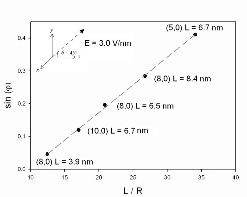
As shown in Fig. 7, we found that is proportional to the aspect ratio of the tube defined as their length to radius . For this external electric field, we obtain a relation almost linear between and the aspect ratio from our simulation results:
| (9) |
where the values of and are about and , respectively. The mechanism of this phenomenon is rather complex: the deformation of a CNT depends both on the polarization and on its local mechanical resistance, the polarization depends on the external electric field and on the atomic polarizability, at the same time, the polarizabilities change following the deformation of the CNT. In our current work for building a global semi-phenomenological model for electrostatic deflection of CNTs, we are preparing some more simulations to try to get a better understanding on this point.
In conclusion, we have demonstrated that a renormalized dipolar model coupled with the AIREBO potential can lead to realistic modelizations of the deflection of various nanotubes under homogeneous external electric fields. The sine of the deflection angle is proportional to the square of the external electric field, which is coherent with the conservation of the total energy of the system and the experimental data. This study also reveals an optimum deflection angle for an electric field making an angle between to with the original tube axis. This result is directly applicable in nanoelectronics where the nanotubes are oriented by means of electric fields in order to realize contacts between conductive plots. Furthermore, we also demonstrate the strong link existing between the deflection angle and the aspect ratio L/R of the tubes.
These results are interesting and are going to be studied in more details in forthcoming publications. For example, we have seen that the local electrostatic forces are strongly inhomogeneous along the tube but it seems that there exists a periodicity of its local variations that should be studied in more details for a wide variety of tubes. Furthermore, we would like to use a regularized monopole-dipole interaction model as developed by A. Mayer et al Mayer et al. (2006), to be able to deal with metallic nanotubes containing free charges. Thus it could be possible to get a better understanding of the experimental results which suggest that metallic nanotubes can have a better response to electric fields than semiconducting ones.
Acknowledgements.
Prof. J.-M. Vigoureux and Dr. A. Mayer are gratefully thanked for fruitful discussions. This work was done as parts of the CNRS GDR-E 2756 and the NATO SFP project 981051. Z. W. acknowledges the support received from the region of Franche-Comté (grant Nb 051129,91) and the Marie Curie conference and training courses grants.References
- Saito et al. (1998) R. Saito, G. Dresselhaus, and M. S. Dresselhaus, Physical Properties of Carbon Nanotubes (Imperial College Press, London, 1998).
- Ke and Espinosa (2005) C.-H. Ke and H. Espinosa, Handbook of Theoretical and Computational Nanotechnology (American Scientific Publishers, 2006), chap. Nanoelectromechanical Systems (NEMS) and Modeling.
- Akita et al. (2001) S. Akita, Y. Nakayama, S. Mizooka, Y. Takano, T. Okawa, Y. Miyatake, S. Yamanaka, M. Tsuji, and T. Nosaka, Appl. Phys. Lett. 79, 1691 (2001).
- Kinaret et al. (2003) J. M. Kinaret, T. Nord, and S. Viefers, Appl. Phys. Lett. 82, 1287 (2003).
- Li et al. (2004) J. Li, Q. Zhang, D. Yang, and J. Tian, Carbon 42, 2263 (2004).
- Krupke et al. (2003) R. Krupke, F. Hennrich, H. Lohneysen, and M. Kappes, Science 301, 344 (2003).
- Hertel et al. (1998) T. Hertel, R. Martel, and P. Avouris, J. Phys. Chem. B 102, 910 (1998).
- Poncharal et al. (1999) P. Poncharal, Z.L. Wang, D. Ugarte, and W. De Heer, Science 283, 1513 (1999).
- El-Hami and Matsushige (2005) K. El-Hami and K. Matsushige, Ultramicroscopy 105, 143 (2005).
- Bao et al. (2006) Q. Bao, H. Zhang, and C. Pan, Appl. Phys. Lett. 89, 063124 (2006).
- Guo and Guo (2003a) Y. Guo and W. Guo, J. Phys. D: Appl. Phys. 36, 805 (2003a).
- Torrens (2004) F. Torrens, Future Generation Computer Systems 20, 763 (2004).
- Mayer and Lambin (2005) A. Mayer and P. Lambin, Nanotechnology 16, 2685 (2005).
- Guo and Guo (2003b) W. Guo and Y. Guo, Phys. Rev. Lett. 91, 115501 (2003b).
- Benedict et al. (1995) L. X. Benedict, S. G. Louie, and M. L. Cohen, Phys. Rev. B 52, 8541 (1995).
- Mayer (2005a) A. Mayer, Phys. Rev. B 71, 235333 (2005a).
- Mayer (2005b) A. Mayer, Appl. Phys. Lett. 86, 153110 (2005b).
- Guo et al. (2004) G. Y. Guo, K. C. Chu, D. sheng Wang, and Chun-gang Duan, Computational Materials Science 30, 269 (2004).
- Kozinsky and Marzari (2006) B. Kozinsky and N. Marzari, Phys. Rev. Lett. 96, 166801 (2006).
- Novikov and Levitov (2006) D. S. Novikov and L. S. Levitov, Phys. Rev. Lett. 96, 036402 (2006).
- Langlet et al. (2004) R. Langlet, M. Arab, F. Picaud, M. Devel, and C. Girardet, J. Chem. Phys. 121, 9655 (2004).
- Langlet et al. (2006) R. Langlet, M. Devel, and P. Lambin, Carbon 44, 2883 (2006).
- Mayer et al. (2006) A. Mayer, P. Lambin, and R. Langlet, Appl. Phys. Lett. 89, 063117 (2006).
- Mayer (2007) A. Mayer, Phys. Rev. B 75, 045407 (2007).
- Stuart et al. (2000) S. J. Stuart, A. B. Tutein, and J. A. Harrison, J. Chem. Phys. 112, 6472 (2000).
- (26) http://lpm.univ-fcomte.fr/personnel/wangz/index.html.
- Brenner et al. (2002) D. Brenner, O. Shenderova, J. Harrison, S. Stuart, B. Ni, and S. Sinnott, Journal of Physics: Condensed Matter 14, 783 (2002).
- Treacy, M. M. J. et al. (2000) M. M. J. Treacy, T. W. Ebbesen, and J. M. Gibson, Nature 381, 678 (1996).
- van Lier et al. (2000) G. van Lier, C. van Alsenoy, V. van Doren, and P. Geerlings, Chem. Phys. Lett. 326, 181 (2000).
- (30) Z. Wang, M. Devel, B. Dulmet, and S. Stuart, submitted.