Simulation of the electromagnetic wall response during Vertical Displacement Events (VDE) in ITER tokamak
Abstract
The key basis for tokamak plasma disruption modeling is to understand how currents flow to the plasma facing surfaces during plasma disruption events. In ITER tokamak, the occurrence of a limited number of major disruptions will definitively damage the chamber with no possibility to restore the device. In the current exchange plasma-wall-plasma, according to the Helmholtz decomposition theorem, our surface current density in the conducting shell - the unknown of our problem - being a vector field twice continuously differentiable in 3D, has been splited into two components: an irrotational (curl-free) vector field and a solenoidal (divergence-free) vector field. Developing a weak formulation form and minimizing the correspondent energy functionals in a Finite Element approach, we have obtained the space and time distribution of the surface currents. We verified successfully our numerical simulation with an analytical solution with pure homogeneous Neumann B.C. and satisfying the necessary existence condition. By considering the iron core presence in JET tokamak, we have split the magnetization currents - the unknowns in some integral equations - into two components, the first producing a magnetic field in the iron region only and the second producing a magnetic field in the vacuum, obtaining thus a better evaluation of the influence of the iron core on the plasma equilibrium. To reduce the influence of the singularities appearing during the surface currents determination in multiply connected domains (L-shaped domains) we have used a conformal transformation method.
1 Introduction
Plasma disruptions in tokamaks represent a significant obstacle in enhancing performance of the plasma regime. In ITER tokamak, the occurrence of a limited number of major disruptions will definitively damage the chamber with no possibility to restore the device. In the next step machines, such as ITER, disruptions impose very challenging requirements on the design of the structural elements of the machine and its in-vessel components. Therefore, empirical approaches for determining the operational space for high performance and, at the same time, disruption-free regimes are excluded. Theoretical and modelling approaches by using the present level of experiments are necessary [1, 2, 3, 4].
It is well known that the necessarily large toroidal currents in tokamak concept suffers from a fundamental problem of stability. The Wall Touching Kink Mode (WTKM) - a nonlinear MHD instability - leads to a dramatic quench of the plasma current within : very energetic electrons are created (runaway electrons) and finally a global loss of confinement happens, i.e. a major disruption. The WTKM are frequently excited during the Vertical Displacement Event (VDE) and cause big sideways forces on the vacuum vessel [5, 6].
Understanding that in disruptions the sharing of electric current between the plasma and the wall plays an important role in plasma dynamics [1, 2, 7, 8], we have developed a wall model that covers both eddy currents, excited inductively, and source/sink currents due to current sharing between the plasma and the wall. We have adopted a triangle representation of the plasma facing wall surface [9] (simplicity and analytical formulas for magnetic field B and magnetic vector potential A of a uniform current in a single triangle). We have considered the wall in its thin wall approximation (reasonable for thin stainless steel structures of the vacuum vessel of about 1-3 cm thick with conductivity ).
In section 2, we define our electromagnetic thin-wall model describing both surface current components. Section 3 describes the weak formulation (under a finite element frame) to determine the unknowns of our problem - the surface currents in the wall. In section 4, numerical and analytical examples are presented. The influence of the presence of an iron core transformer tokamak (like in JET tokamak) is described in section 5. The summary is given in section 6.
2 Electromagnetic thin-wall model
According to Helmholtz decomposition theorem, our surface current density in the conducting shell (a vector field twice continuously differentiable in 3D) can be split into two components: an irrotational (curl-free) vector field and a solenoidal (divergence-free) vector field [9]
| (1) |
where is the divergence free surface current (eddy currents), is the source/sink current (S/SC) with potentially finite divergence in order to describe the current sharing between plasma and wall, is surface wall conductivity, represents the thickness of the current distribution, is the stream function of the divergence free component (eddy currents), is the unit normal vector to the wall while is the source/sink potential (a surface function).
The S/S-current in Eqs. (1) is determined from the continuity equation of the S/S currents across the wall
| (2) |
where is the density of the current coming from/to the plasma, for flowing from the plasma to the wall.
Faraday law gives
| (3) |
where is the magnetic vector potential of the magnetic field B, while is the electric potential. Equations (2, 3) describe the current distribution in the thin wall given the following sources: the current density coming from/to the plasma , the normal to the wall components of the magnetic field due to the plasma (), to different coils () and to the iron core transformer () all as functions of position and time. It is to note that Equation (2) for is independent from Equation (3), but contributes via to the r.h.s. of Equation (3).
In our finite element solving approach, with a uniform surface current =const inside each triangle, the magnetic vector potential has been calculated with the relation
| (4) |
where the superscripts and are designating the magnetic vector potential due to eddy currents and to the sink/source currents, respectively. The summation is over the FE triangles, while the surface integral is taken over the considered FE triangles analytically.
The equation for the stream function is given by [10, 11]
| (5) |
where are representing different perpendicular to the wall magnetic field components (due to plasma, coils, eddy currents, sink/source currents and iron core transformer).
To close the system of equations, the Biot-Savart relation for is necessary.
3 Energy principles for the wall currents
The tokamak wall configurations being complex and presenting different material interfaces, solving the strong form (PDE) is not always efficient. Therefore, we have used a weak formulation - a finite element method formulation - for our problem. Thus, was obtained by minimizing the functional [9, 12, 13, 14, 15]
| (6) |
where is taken along the wall surface, is taken along the edges of the conducting surfaces with the integrand representing the surface current normal to the edges. This last integral takes into account the external voltage applied to the wall edges and vanishes as happens in typical cases.
4 Simulation of Eddy and Source/Sink currents
4.1 Numerical solution
We have adopted a triangle electromagnetic representation of the thin wall, based on the expressions for and of a uniform surface current =const inside each triangle. The two energy functionals for and for constitute our electromagnetic wall model for the wall touching kink and vertical modes. The substitution of as a set of plane functions inside triangles leads to the finite element representation of as quadratic forms for unknowns in each vertex. The minimization of quadratic forms and
leads to a linear systems of equations with Hermitian symmetric-positive definite matrices which can be solved using the Cholesky decomposition.
The matrix equations obtained after minimization and decoupling between equations for eddy and SS currents (easily achieved by matrix multiplications) are [13, 14]
| (8) |
with vector sources :
| (9) |
is the vertex number, is the ”wall-time-step”, while the superscript represents the time slice. Finally, the calculation of the wall currents is reduced to the two relations Eqs. (8) implemented in our code.
In Table 1, the size of the matrices for the 21744 triangles and 11223 vertexes of the FE discretization of ITER wall is given. As output, the code returns the values of and in all vertexes, allowing the calculation of the A and B of the wall currents in any point .
| \brMatrix | Memory size [KB] |
|---|---|
| \mr | 984,030 |
| 855,106 | |
| 917,305 | |
| 917,305 | |
| \br |
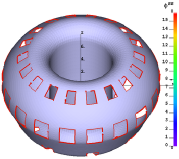
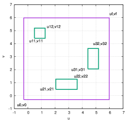
In Figure 1 a finite element discretization of ITER wall is presented.
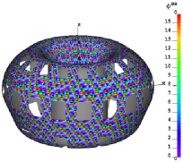
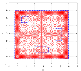
In Figure 2, an example of our calculation, with a conceived distribution is given. In our calculations, both wall thickness and conductivity can be considered as variable too. For a ITER wall with 11223 vertexes and 21744 triangles, the generation of the matrix and its Choleski decompositions takes , after this, the solution of the equation takes several seconds for given distributions.
4.2 Analytical solution for
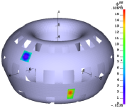
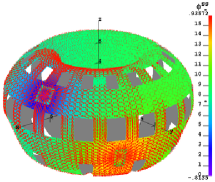
For a shell with elliptical cross-section and three holes with the correspondent geometry in a curvilinear coordinate system in Fig. 3 (left) and considering =1, we have to solve the equation
| (10) |
with pure homogeneous Neumann B.C. and the following existence condition which is satisfied:
| (11) |
The analytical has been chosen in the form [11, 12]
| (12) |
The analytical solution is presented in Figure 3. If for one hole the relative error was of 0.003 for a grid with a mesh , for three holes the error is 5 times greater. This is due to the presence of many re-entry corners (L-shaped domains). This problem has been solved by using conformal transformations so that the relative error became significantly smaller.
4.3 Analytic solution for
Writing Eq. (5) in the same curvilinear coordinate system , where two of the covariant basis vectors and are tangential to the wall surface ( has been considered constant)
| (13) |
where, as before, is the stream function of the divergence free component (eddy currents), and are the covariant metric coefficients and is the 2D Jacobian at the wall surface. is the magnetic field on the wall surface. We have
| (14) |
and by integrating this equation on the surface delimited by curve (wall and/or hole boundaries) we obtain
| (15) |
is the magnetic flux through the surface. Thus, Eq. (15) gives the necessary boundary conditions (of Dirichlet type) for the parabolic equation (13).
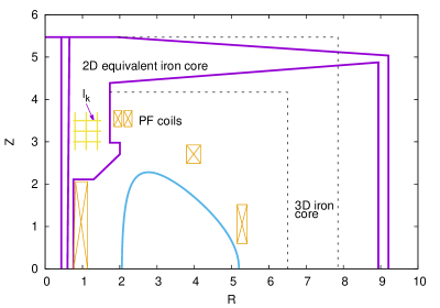
5 Calculation the iron core transformer influence in simulation of the wall response during VDE in JET tokamak
Due to the high non-linear dependence of the MHD solutions on the iron permeability of the iron-core tokamak transformer, the complexity of equilibrium and stability calculations increases considerably. A boundary integral equations method to calculate the magnetostatic part of the MHD equations is presented in the following and has been used first by us, in a simplified form, for equilibrium calculation for the T15 tokamak [17]. Let us consider an equivalent 2D magnetic circuit (i.e. with rotational symmetry) of the JET tokamak with the meridian cross-section presented in Fig. 4. It is known that the surface current density distribution along a curve separating two homogeneous media and of constant magnetic permeabilities ( and in the outer and inner domain respectively of the curve), is described by a Fredholm integral equation of second kind
| (16) |
where: is the tangential magnetic field component at the curve in produced by a unit surface current in , is the tangential magnetic field component at the curve produced by an external known source.
For the real case, the curve was considered as the sum of all interfaces between subdomains of different permeabilities, then on each segment of curve (a Liapunov curve) the surface current density, supposed to be Hölder continuous and of bounded variation, admits a uniform convergent expansion
| (17) |
where now contours () with discrete segments for each contour have been considered. are the unknown coefficients, are orthogonal polynomials of order , while are weight functions (given the azimuthally symmetric geometry, we have used Legendre polynomials, ). Thus, Eq. (16) becomes
| (18) |
Once the iron surface currents have been determined, their contribution to the external magnetic field can be calculated. Evidently, an iterative feedback approach has to be considered.
6 Summary
Within the framework of a thin wall limit and a triangular representation of the wall surface, both divergence-free eddy and source/sink currents are represented by the same model of a uniform current density inside each triangle. This model is implemented in the SSC and the shell simulation code SHL. On request, our code received the status of open source license: to be used now by the entire EUROfusion community in modelling Wall Touching Kink Modes and Vertical Displacement Events. Recently, our approach has been implemented successfully into the JOREK-STARWALL code [18].
As a next step, in order to model a real disruption, we have to introduce the following input data in our code
| (19) |
Acknowledgments
This work has been
partially carried out within the framework of the EUROfusion Consortium and has received funding from the Euratom research and training programme 2014–2018 under grant agreement no. 633053. The views and opinions expressed herein do not necessarily reflect those of the European Commission.
References
References
- [1] Zakharov L E 2008 The theory of the kink mode during the vertical plasma disruption events in tokamaks, Physics of Plasmas. 15 062507
- [2] Zakharov L E, Galkin S A and Gerasimov S N 2012, Understanding disruptions in tokamak, Physics of Plasmas. 19 055703
- [3] Merkel P and Strumberger E 2015, Linear MHD stability studies with the STARWALL code, arXiv:1508.04911.
- [4] Hoelzl M, Merkel P, Huysmans G T A, Nardon E, McAdams R and Chapman I 2012, Coupling the JOREK and STARWALL Codes for Non-linear Resistive-wall Simulations, Journal of Physics: Conference Series, 401, 012010
- [5] Ricardo V et al. 2009, Progress in understanding halo current at JET Nuclear Fusion 49 055012
- [6] Ricardo V, Noll P and Walker S P 2000, Forces between plasma, vessel and TF coils during AVDEs at JET. Nuclear Fusion 40 1805
- [7] Zakharov L E, Xiong H, Hu D, Xujing L and Atanasiu C V 2013, Hiro currents: physics and a bit of politics, Theory and Simulation of Disruptions Workshop, July 17-19, 2013,PPPL, Princeton NJ, USA
- [8] Zakharov L E, Guazzotto L Xujing L and Atanasiu C V 2013, Outline of our work on disruption, Informal discussion, August 14, 2013, PPPL, Princeton NJ, USA
- [9] Zakharov L E, Atanasiu C V, Lackner K, Hoelzl M, and Strumberger E 2015, Electromagnetic thin-wall model for simulations of plasma wall-touching kink and vertical modes, Journal of Plasma Physics. 81 515810610
- [10] Atanasiu C V and Zakharov L E 2013, Response of a partial wall to an external perturbation of rotating plasma, Phys. of Plasmas 20 092506
- [11] Hoelzl M, Merkel P, Huysmans G T A, Atanasiu C V et al. 2012, Non-linear simulations of MHD instabilities in Tokamaks including Eddy current effects and perspectives for the extension to Halo currents, Journal of Physics: Conference Series 401 012010
- [12] Zakharov L E, Atanasiu C V, Xujing L 2017 Interface of wall current modeling with disruption simulation codes, JOREK-STARWALL discussion meeting, IPP, Garching bei München, Germany, March 10, 2017.
- [13] Atanasiu C V, Zakharov C V, Lackner K, Hoelzl M and Strumberger E 2017, Simulation of the electromagnetic wall response to plasma wall-touching kink and vertical modes with application to ITER, 59th Annual Meeting of the APS Division of Plasma Physics, Milwaukee, WI, US, October 23-27, 2017 (oral)
- [14] Atanasiu C V, Zakharov L E, Lackner K, Hoelzl M, Artola F J, Strumberger E and Xujing L 2017, Modelling of wall currents excited by plasma wall-touching kink and vertical modes during a tokamak disruption, with application to ITER, 17th European Fusion Theory Conference, Athens – Greece, October 9-12, 2017 (oral).
- [15] Atanasiu C V, Zakharov L E, Lackner K, Hoelzl M and Strumberger E 2017, Wall currents excited by plasma wall-touching kink and vertical modes, JOREK Meeting, Prague - 20-24/03/2017 (oral).
- [16] Zakharov L E, Xujing L, Gerasimov S N and JET Contributors, Atanasiu C V, Lackner K, Hoelzl M, Strumberger E and Artola Such J 2017, Tokamak MHD and its interface (ssec) with the wall model, 30th ITPA-MHD Disruptions & Control topical group workshop October 9 2017, Fusion For Energy, Barcelona, Spain (oral)
- [17] Atanasiu C V and Zakharov L E 1990, Description of the magnetohydrodynamic equilibrium in iron core transformer tokamaks, Nuclear Fusion 30 1027
- [18] Artola F J, Atanasiu C V, Hoelzl M, Huijsmans GTA, Lackner K, Mochalskyy S, Oosterwegel G, Strumberger E and Zakharov L E 2018 Second intermediate report for ITER project IO/16/CT/4300001383 on the Implementation and validation of a model for halo-currents in the nonlinear MHD code JOREK and demonstration of 3-D VDEs simulations in ITER, Version 2, March 5th 2018