Design algorithms of driving-induced nonreciprocal components
Abstract
We utilize an effective Hamiltonian formalism, within the Floquet scattering framework, to design a class of driving-induced non-reciprocal components with minimal complexity. In the high driving-frequency limit, where our scheme is formally applicable, these designs demonstrate a leading order non-reciprocal performance which is inverse proportional to the driving frequency. Surprisingly, the optimal non-reciprocal behavior persists also in the slow driving regime. Our approach highlights the importance of physical loops in the design of these driven non-reciprocal components.
I Introduction
The quest for schemes that lead to the realization of novel non-reciprocal components has been, for many years now, a subject of intense activity LRWZHL12 ; Alu0 ; mezler ; Alu1 ; Alu2 ; Alu3 ; YF11 ; SYF15 . On the fundamental level these schemes must invoke mechanisms that violate time-reversal symmetry – the latter being in the core of wave transport reciprocity theorems LL60 ; C45 ; H84 ; ST07 . On the technological level, the employed designs must satisfy a set of requirements; the non-reciprocal components have to be bounded by the small footprint of the devices, they have to be easily fabricated, have small cost, small energy consumption etc. Needless to say that any achievement along these lines can influence the progress of wave transport management in areas as diverse as electromagnetism, acoustics, thermal, matter and quantum waves. At the same time, the development of such new class of circulators, isolators and other non-reciprocal components will have dramatic implications in the next generation of communication, protection, imaging, and quantum information schemes.
In the electromagnetic framework, non-reciprocal transport has been mainly achieved via magneto-optical materials ZK97 ; DBZHWGHP05 . These exotic materials are normally very lossy when deposited at thin films. Moreover, the weak nature of the magneto-optical effects makes them incompatible with on-chip integration. Similar problems appear in acoustics, where magneto-acoustic effects are even weaker than their optical counterparts L05 . An alternative approach to directional wave transport utilizes nonlinear spatially asymmetric structures Alu0 ; mezler ; BFBRCEK13 ; NBRMCK14 ; LC11 ; Yang14 ; LYC09 ; LGTZ10 ; BTD11 . The nonlinear effects can be different for the forward and backward propagating waves, thus resulting in intensity-dependent propagation asymmetry. The same principle applies also for phononic heat transport and can lead to thermal diodes and rectifiers mezler ; LRWZHL12 ; WL08 ; LWC04 . Despite this success, nonlinear mechanisms impose limitations on the operational amplitude of the device - an undesirable feature from the engineering perspective. At the same time, in the case of electromagnetic and acoustic waves, they often introduce inherent signal distortions (generation of higher harmonics) mezler .
Parallel approaches that aim to realize non-reciprocal components have capitalized on active schemes. These designs utilize spatio-temporal modulations of the impedance profile of the propagating medium and provide a promising alternative for the realization of compact, reconfigurable non-reciprocal components Alu0 ; Alu1 ; Alu2 ; FSSHA14 ; YF11 ; LK15 ; SLFK16 . In fact, when paired with the emerging field of Floquet engineering Goldman2014 ; Eckardt2015 ; IK15 , they might provide a powerful approach that can produce frequency and bandwidth-tailored non-reciprocal transport Li2018 ; LiBT2018 .
In this paper we will utilize the toolbox of Floquet engineering, in order to design a class of driving-induced non-reciprocal components with minimal complexity. Our design scheme is demonstrated using the universal framework provided by coupled mode theory. Although it is formally applicable at the high-frequency modulation limit, it also provide guidance for the design of non-reciprocal components in the low-frequency modulation regime. The proposed methodology highlights the importance of physical loops in these designs. Moreover, it allow us to derive analytical expressions for the left/right transmittance asymmetry which, in the high-frequency modulation regime, is . We find that the theoretical expressions that describe the transmittance asymmetry of this class of isolators and circulators matches nicely with the numerical results and in many occasions can reach the maximum value of non-reciprocal behavior.
The structure of the paper is as follows. In Sec. II, we present the Floquet engineering scattering formalism in the limit of high modulation frequency. The method utilizes the notion of effective Floquet Hamiltonian. In the next Sec. III, we implement this formalism for the design of reconfigurable non-reciprocal components with leading order performance which is inverse proportional to the driving frequency. In Subsec. III.1, we discuss the applicability of our scheme for the case of an isolator and demonstrate the validity of our approach via a specific model. The applicability of the method in the case of a circulator is shown in Subsec. III.2. In Sec. IV, we demonstrate the persistence of optimal performance of our designs in the low driving frequency regimes via numerical examples. Finally, our conclusions are given at the last Sec. V.
II Floquet scattering in the high modulation frequency limit
We consider periodically time-modulated systems consisting of coupled modes. In the context of coupled mode theory such a (hermitian) system can be described by a time-dependent -dimensional Hamiltonian . It turns out that the evolution of such systems can be expressed in terms of a -dimensional time-independent effective (Floquet) Hamiltonian and a micromotion operator Goldman2014 . The former describes the long time (stroboscopic) dynamics while the latter accounts for the evolution within one period of the driving. This formalism allows us to invoke a systematic high-frequency expansion in for both the effective Hamiltonian and the micromotion operator Eckardt2015 . A benefit of this representation is the fact that one can eliminate the artificial dependence of the effective Hamiltonian on the driving phase (i.e. initial time of periodic driving) which can be elusive as far as symmetry preservation is concerned Eckardt2015 .
At the same time, the notion of and has been proven useful in the analysis of Floquet scattering settings LiBT2018 . The latter constitutes the natural framework where the scattering properties of driven targets can be inferred from the dynamics of their isolated (i.e. in the absence of coupling with leads) counterparts Li2018 . The proposed approach LiBT2018 allows us to treat the driven target as a static one – which is described by the effective Hamiltonian – coupled to leads. In this framework the coupling constants that describe the coupling of the target with the leads are also time-independent - albeit they are different from their bare values due to a renormalization procedure which involves information encoded in the micromotion.
To be specific, we consider a time-periodic driven target which is coupled with identical leads. The coupling strengths between the target and the leads are given by the bare coupling matrix . The transport characteristics of this system are given by the Floquet scattering matrix , which couples the outgoing propagating channels with the incoming ones. Below we will assume for simplicity that in the high-driving frequency domain there exists only one propagating channel in each lead. The case of multimode leads, although more cumbersome, can be also worked out along the same lines. The flux-normalized scattering matrix , up to order , is LiBT2018
| (1) |
where is the identity matrix, is the group velocity of the propagating channel, and is the renormalized bare coupling due to the micromotion . The latter can be approximated as
| (2) |
where . The term in the denominator of Eq. (1) represents the fact that the target is not isolated. The origin of these two terms is different: the first one describes the channel-coupling induced renormalization to the close-system Hamiltonian while the second one is optional and describes potential material gain/loss of the target ( is a non-Hermitian diagonal matrix). In fact, in an alternative formulation of the problem, we could absorb the gain/loss properties of the isolated system in a composite coupled mode Hamiltonian with a corresponding .
Finally, the high-frequency expansion of the effective Hamiltonian is given in many references LiBT2018 ; Eckardt2017 , and it is shown here for the sake of completeness and convention consistency:
| (3) |
Hereafter we will consider tight-binding leads with dispersion relation (in units of coupling). In this case, (appearing in ) and the group velocity , where .
Finally, we point out the structural similarities between the -matrix given by Eq. (1) and the scattering matrix associated with static targets, when the latter is written in terms of the Hamiltonian of the corresponding isolated system, see for example Refs. FS1997 ; LiST2018 . These similarities can be proven useful in other investigations where scattering properties of complex/ chaotic systems are investigated. Interestingly enough, although the formula Eq. (1) is formally correct up to order , its performance typically go beyond this order (compare, for example, Fig. 2b and Fig. 2a). The reason is subtle but we might appreciate it from the preserved structure and general properties. For example, in the absence of gain/loss, i.e., , the approximate scattering matrix in Eq. (1) preserves the unitarity as it should.
Below we will present our design strategy for the realization of non-reciprocal components with minimal complexity. It consists of two steps: first we utilize the Floquet engineering within the scattering set-up to develop driving schemes that provide optimal non-reciprocal responses in the high-frequency limit. At the second step we demonstrate that these same designs manifest optimal transmittance asymmetry also in the limit of slow driving. Our proposal is supported by detail simulations.
III Design of nonreciprocal components with minimal complexity: High frequency limit –
First we utilize Eq. (1) to derive analytical expressions for the left/right transmittance asymmetry up to leading order in driving frequency , i.e. . A subsequent optimization of these expressions with respect to various driving parameters, allow us to engineer non-reciprocal components (circulators, isolators) with maximum transmittance asymmetry.
III.1 Reconfigurable Isolators
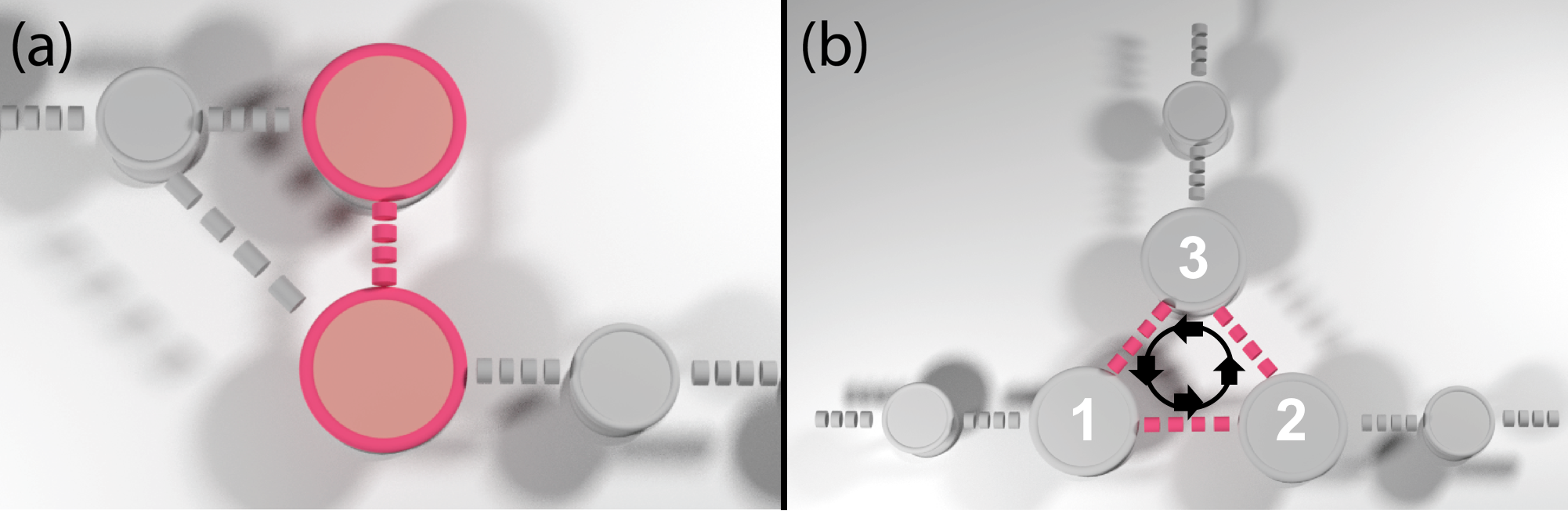
The first reconfigurable nonreciprocal component that we design is an isolator. We consider the simplest possible scenario involving two driving modes, i.e., , coupled to two leads note0 . We first observe that the leading order contribution in the expression Eq. (1) for the scattering matrix, originates solely from the effective Floquet Hamiltonian (see Eq. (3)). Due to its Hermitian nature, however, the matrix cannot lead to a transmittance asymmetry . One needs, therefore, to “break” this Hermiticity constraint – an operation performed by incorporating in the non-Hermitian diagonal matrix (see previous discussion). As a result, the matrix in Eq. (1) has, up to a common factor, complex diagonal matrix elements while its off-diagonal elements are complex conjugates of each other . This, by itself, does not guarantee that , let alone that . The latter requirement can be fulfilled only when the bare coupling matrix has off-diagonal elements which lead to a mixing of diagonal and off diagonal terms of after performing the multiplication (see Eq. (1)). The presence of off-diagonal elements in suggests an isolator design that involves physical loops. An example of such system is shown in Fig. 1a and it is mathematically modeled via the bare coupling matrix . We stress again that this design is a direct consequence of the theoretical analysis of Eq. (1).
Next we proceed with the evaluation of transmittance asymmetry for the design of Fig. 1a. For simplicity, we assume uniform gain/loss, i.e., . Furthermore, we parametrize the effective Hamiltonian as and the micromotion operator as . In the above parametrization we have consider terms up to order . Specifically, since the target in the absence of modulation is recirpocal, we have that while generally . Similarly, the components of the micromotion operator are and .
It turns out that the matrix elements and are essential for the presence of the transmittance asymmetry. Their origin are traced back to the presence of driving and can be associated with an effective gauge field FangFan2012 . To appreciate the importance of and , we have evaluated the transmittance asymmetry explicitly up to . Using Eq. (1) we get
| (4) |
where the matrix and has been evaluated using the first two terms in Eq. (3).
Let us now consider a specific driving protocol described by the time-dependent Hamiltonian
| (5) |
where and . Without any loss of generality we will assume that the starting time of the driving scheme is such that . Then the other two driving phases can be measured relative to , and can be used to optimize the transmittance asymmetry. For the specific driving protocol of Eq. (5), we have that , and . A theoretical expression for the transmittance asymmetry , as a function of incident frequency , can be calculated by direct substitution of into Eq. (4). Specifically we find that up to , the following expression for the transmittance asymmetry
| (6) |
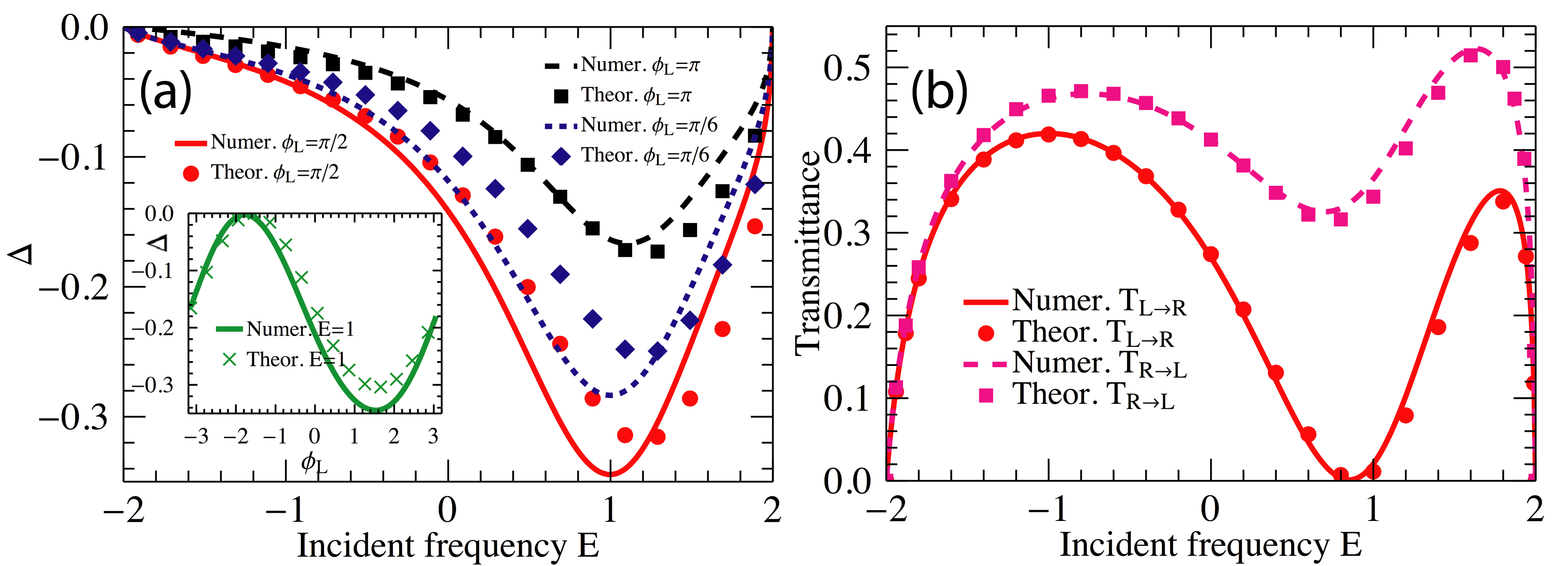
which takes its maximum value for .
In Fig. 2a we report the theoretical predictions Eq. (4) for the transmittance asymmetry , together with the outcome of the simulations (where the exact Floquet scattering matrix has been used Li2018 ). Various values of the driving phases (for fixed ) have been considered. In all cases we observed a nice agreement between theory and numerics. Moreover, we find that the maximal transmittance asymmetry occurs when , as predicted by our theory. This optimal phase choice is further verified in the inset of Fig. 1a where we report versus for a fixed incident wave-frequency . At Fig. 2b we also report the individual left and right transmittances versus the incident wave frequency, for the optimized phase configuration . The theoretical results (symbols) have been calculated using the (approximated) expression Eq. (1) for the -matrix (high frequency limit).
III.2 Reconfigurable Circulators
We proceed with the design of circulators. As before, we consider a design with the minimal complexity consisting of three (driven) modes, each of which is coupled to a lead (i.e., ) with equal coupling strength . As opposed to the case of (two-channel) isolators, here the presence of the non-Hermitian term (describing material losses/gain) is not necessary. The non-Hermiticity is automatically satisfied by the presence of the propagating channel in the third lead and thus we will assume below that . At the absence of driving, the system is respecting a rotational symmetry. We want to design a counter-clock-wise circulator, i.e. a three-port structure for which counter-clock-wise transmittances , while transmittances in the clock-wise direction are (essentially) zero i.e. . Obviously, such a structure must demonstrate a strong positive transmittance asymmetry between two consequent leads. A schematics of this circulator is shown in Fig. 1b.
Similar to the case of the isolator, we parametrize the effective Hamiltonian as
| (7) |
where and . At the same time the micromotion operator can be written as
| (8) |
with , .
From Eqs. (1,7,8) we are able to derive the following expression for the transmittance asymmetry up to between two consequent leads (say lead 1 and lead 2, see Fig. 1b):
| (9) |
where the matrix is defined below Eq. (4). Above originates from the effective Hamiltonian and from the micromotion. Due to the structural symmetry of the undriven system, Eq. (9) applies also for the transmittance asymmetry between the leads () and ().
Let us work out a specific driving protocol described by the following time-periodic Hamiltonian
| (10) |
where the periodic modulation pertains to the couplings . We want to identify the driving phases configuration for which the circulator will demonstrate maximum performance. In this case we have that , , (and cyclicly , etc) note2 . According to Eq. (9), the associated transmittance asymmetry reads
| (11) |
The above equation indicates that depends only on the relative driving phases i.e. and . Without loss of generality, we set . From Eq. (11) we find that the phase configuration and (or similarly and ) can produce the maximum asymmetry up to order . We point out that a similar driving phase configuration has been implemented recently in the case of mode-modulated circulators Alu2014 - though in our case it is important to realize that this optimal configuration emerged as a result of our optimization approach. We can further optimize with respect to the coupling parameter . It turns out that for the specific case of optimal phases the critical coupling (perfect impedance matching) occurs for .
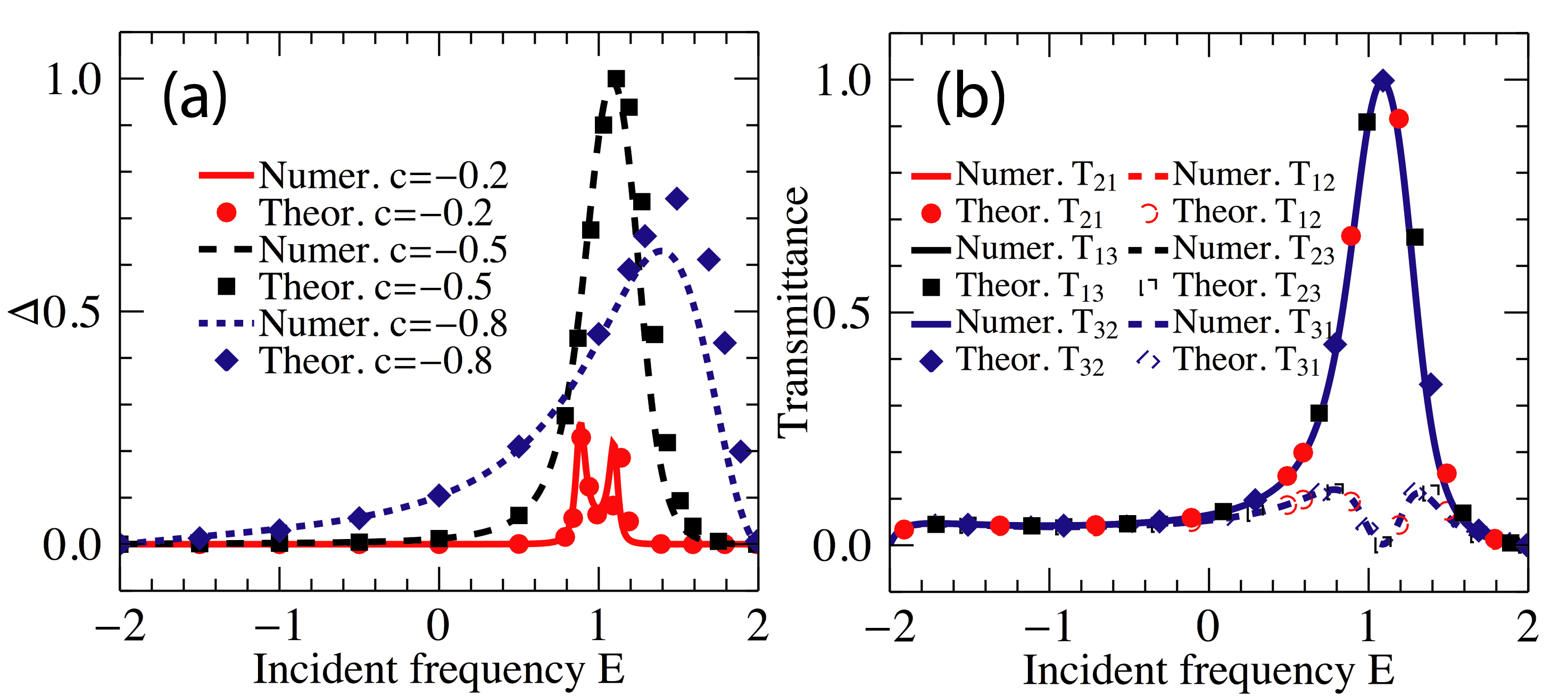
In Fig. 3a, we show the numerical data for the transmission asymmetry between channels 1 and 2 (see Fig. 1b) versus the incident frequency for the optimal phase configuration , and . Various coupling strengths have been considered. At the same figure we also report the theoretical results for , see Eq. (11). We found a non-monotonic behavior of the transmittance asymmetry with respect to the coupling due to the impedance mismatch. For the predicted coupling , the system demonstrates a nonreciprocal behavior which is as high as .
The individual transmittances versus incident frequency (for the optimal phase and coupling configurations) are reported in Fig. 3b. Both theoretical (using Eq. (1)) and numerical (using the exact Floquet scattering matrix Li2018 ) results fall nicely one on top of the other and indicate that for the optimal phase configuration while at a frequency range around .
IV Nonreciprocal components with minimal complexity: Low driving frequency limit
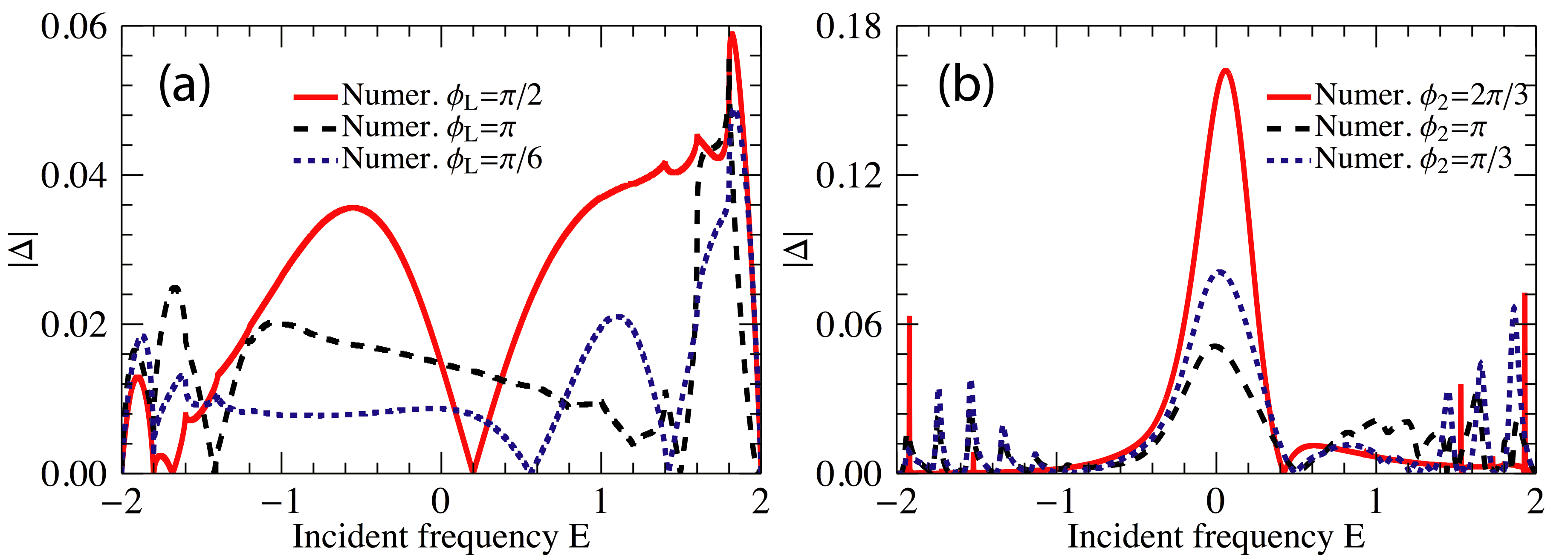
Although the Floquet -matrix can be always expressed in terms of , one cannot use any more the approximated forms Eqs. (1,2,3) in the slow-frequency driving limit. As a result, our theoretical expressions Eqs. (4,9) for the transmittance asymmetry are not any more applicable. We have found, nevertheless, that the driving designs that lead to optimal non-reciprocity in the case of high-frequency driving schemes are applicable even in the case of small driving frequencies. This conclusion has been supported via detail numerical simulations for various drivings. Typical examples are shown in Fig. 4a,b where we plot the numerical results for (using the exact Floquet scattering matrix Li2018 ) for the previous designs of isolators and circulators. A small driving frequency is now used. In the case of an isolator, see Fig. 4a, we report for three representative driving phases . An overall optimal asymmetric transmittance is observed for which is the predicted optimal phase in the case of high-frequency driving schemes (see Fig. 2). Similarly, in Fig. 4b we report the behavior of for and various values of and . Again we find that an overall optimal transmittance asymmetry is observed when which is the predicted optimal driving phase in the case of high-frequency driving schemes.
V Conclusion
We have developed a scheme for designing optimal non-reciprocal components (isolators, circulators etc) which utilize the concept of Floquet engineering. In the high-frequency modulation limit we developed a theoretical formalism that relies on the notion of effective Floquet Hamiltonians and allows us to express the transmittance asymmetry in inverse powers of the modulation frequency. An analysis of the theoretical expressions provides guidance for the geometrical design of non-reciprocal components and driving schemes that can lead to optimal performance. Specifically, the method highlights the importance of physical loops in getting maximum non-reciprocal efficiency. Detail numerical investigation indicates that these designs can provide optimal non-reciprocal transport even in the case of low driving frequencies.
Our approach can find promising applications in the framework of classical electromagnetic and acoustic wave theories as well as matter wave physics. Another potential application could be in the framework of thermal transport where the design of reconfigurable thermal diodes is a challenging research direction.
VI Acknowledgments
The authors acknowledge useful discussings with Prof. B. Shapiro. This research was partially supported by DARPA NLM program via grant No. HR00111820042, by an AFOSR grant No. FA 9550-10-1-0433, and by an NSF grant EFMA-1641109. The views and opinions expressed in this paper are those of the authors and do not reflect the official policy or position of the U.S. Government.
References
- (1) R. Fleury, D. Sounas, M. R. Haberman, and A. Alú, Nonreciprocal acoustics, Acoust. Today 11, 14 (2015).
- (2) N. Li, J. Ren, L. Wang, G. Zhang, P. Hänggi, B. Li, Phononics: Manipulating heat flow with electronic analogs and beyond, Rev. Mod. Phys. 84, 1045 (2012).
- (3) C. Caloz, A. Alú, S. Tretyakov, D. Sounas, K. Achouri, Z-L Deck-Léger, Electromagnetic Nonreciprocity, Phys. Rev. Applied 10, 047001 (2018).
- (4) D. L. Sounas, A. Alú, Non-reciprocal photonics based on time modulation, Nature Photonics 11, 774 (2017).
- (5) A. B. Khanikaev, A. Alú, Optical isolators: nonlinear dynamic reciprocity, Nat. Phot. 9, 359 (2015).
- (6) A. A. Maznev, A. G. Every, and O. B. Wright, Reciprocity in reflection and transmission: What is a “phonon diode”?, Wave Motion 50, 776 (2013).
- (7) Z. Yu, S. Fan, Optical Isolation: A non-magnetic approach, Nature Photonics 5, 517 (2011).
- (8) Y. Shi, Z. Yu, S. Fan, Limitations of nonlinear optical isolators due to dynamic reciprocity, Nat. Phot. 9, 388 (2015).
- (9) L. D. Landau and E. M. Lifshitz, Electrodynamics of Continuous Media (Addison-Wesley, Reading, MA, 1960).
- (10) H. B. G. Casimir, On Onsager’s principle of microscopic reversibility, Rev. Mod. Phys. 17, 343 (1945).
- (11) H. A. Haus, Waves and Fields in Optoelectronics (Prentice-Hall, Englewood Cliffs, NJ, 1984).
- (12) B. E. A. Saleh and M. C. Teich, Fundamentals of Photonics, (Wiley InterScience, Hoboken, NJ, 2007).
- (13) A. K. Zvezdin and V. A. Kotov, Modern Magneto-optics and Magneto-optical Materials, (Taylor & Francis, London, 1997).
- (14) H. Dótsch, N. Bahlmann, O. Zhuromskyy, M. Hammer, L. Wilkens, R. Gerhardt, P. Hertel, and A. F. Popkov, Applications of magneto-optical waveguides in integrated optics: Review, J. Opt. Soc. Am. B 22, 240 (2005).
- (15) B. Lüthi, Physical Acoustics in the Solid State (Springer, Berlin, 2005).
- (16) N. Bender, S. Factor, J. D. Bodyfelt, H. Ramezani, D. N. Christodoulides, F. M. Ellis, and T. Kottos, Observation of Asymmetric Transport in Structures with Active Nonlinearities, Phys. Rev. Lett. 110, 234101 (2013).
- (17) F. Nazari, N. Bender, H. Ramezani, M.K. Moravvej-Farshi, D. N. Christodoulides, and T. Kottos, Optical isolation via -symmetric nonlinear Fano resonances, Opt. Express 22, 9574 (2014).
- (18) S. Lepri and G. Casati, AsymmetricWave Propagation in Nonlinear Systems, Phys. Rev. Lett. 106, 164101 (2011).
- (19) B. Peng, S. K. Oz̈demir, F. Lei, F. Monifi, M. Gianfreda, G. L. Long, S. Fan, F. Nori, C. M. Bender and L. Yang, Nonreciprocal light transmission in parity-time-symmetric whispering-gallery microcavities, Nat. Phys. 10, 394 (2014).
- (20) B. Liang, B. Yuan, J.-C. Cheng, Acoustic Diode: Rectification of Acoustic Energy Flux in One-Dimensional Systems, Phys. Rev. Lett 103, 104301 (2009).
- (21) B. Liang, X. S. Guo, J. Tu, D. Zhang and J. C. Cheng, An acoustic rectifier, Nature Materials 9, 989 (2010).
- (22) N. Boechler, G. Theocharis, C. Daraio, Bifurcation-based acoustic switching and rectification, Nat. Mat. 10, 665 (2011).
- (23) L. Wang and B. Li, Phononics gets hot, Phys. World 21, 27 (2008).
- (24) B. Li, L. Wang, and G. Casati, Thermal Diode: Rectification of Heat Flux, Phys. Rev. Lett. 93, 184301 (2004).
- (25) R. Fleury, D. L. Sounas, C. F. Sieck, M. R. Haberman, A. Alú, Sound Isolation and Giant Linear Nonreciprocity in a Compact Acoustic Circulator, Science 343, 516 (2014)
- (26) H. Li, T. Kottos, Linear thermal circulator based on Coriolis forces, Phys. Rev. E 91, 020101(R) (2015).
- (27) S. Suwunnarat, H. Li, R. Fleischmann, T. Kottos, Low-temperature linear thermal rectifiers based on Coriolis forces, Phys. Rev. E 93, 042115 (2016).
- (28) N. Goldman and J. Dalibard, Periodically Driven Quantum Systems: Effective Hamiltonians and Engineered Gauge Fields, Phys. Rev. X 4, 031027 (2014).
- (29) A. Eckardt and E. Anisimovas, High-frequency approximation for periodically driven quantum systems from a Floquet-space perspective, New J. Phys. 17, 093039 (2015).
- (30) A. P. Itin and M. I. Katsnelson, Effective Hamiltonians for Rapidly Driven Many-Body Lattice Systems: Induced Exchange Interactions and Density-Dependent Hoppings, Phys. Rev. Lett. 115, 075301 (2015)
- (31) H. Li, T. Kottos, and B. Shapiro, Floquet-Network Theory of Nonreciprocal Transport, Phys. Rev. Applied 9, 044031 (2018).
- (32) H. Li, B. Shapiro, and T. Kottos, Floquet scattering theory based on effective Hamiltonians of driven systems, Phys. Rev. B 98, 121101(R) (2018).
- (33) A. Eckardt, Colloquium: Atomic quantum gases in periodically driven optical lattices, Reviews of Modern Physics 89, 011004 (2017).
- (34) Y. V. Fyodorov and H.-J. Sommers, Statistics of resonance poles, phase shifts and time delays in quantum chaotic scattering: Random matrix approach for systems with broken time-reversal invariance, J. Math. Phys. (N.Y.) 38, 1918 (1998).
- (35) H. Li, S. Suwunnarat, T. Kottos, Statistical design of chaotic waveforms with enhanced targeting capabilities, Phys. Rev. B 98, 041107(R) (2018).
- (36) We remark that one-mode driving can not lead to isolation with performance, which is obvious when setting in Eq. (1) and considering that both the effective Hamiltonian and the micromotion are scalar in this case. Notice that we exclude the possibility of the lead-lead coupling, which is not captured by Eq. (1)LiBW2012 .
- (37) H. Li, B. K. Agarwalla, and J.-S. Wang, Generalized Caroli formula for the transmission coefficient with lead-lead coupling, Phys. Rev. E 86, 011141 (2012).
- (38) K. Fang, Z. Yu, and S. Fan, Realizing effective magnetic field for photons by controlling the phase of dynamic modulation, Nat. Photonics 6, 782 (2012).
- (39) For the example Eq. (5) (and similarly the previous one (10)), the effect of the micromotion is absent within order . It will be interesting to work in the the complex hermitian Hamiltonian to investigate the interplay between the effective Hamiltonian and the micromotion within order , which, however, is beyond the current purpose to design asymmetry in the nonreciprocal components.
- (40) N. A. Estep, D. L. Sounas, J. Soric, and A. Alu, Magnetic-free non-reciprocity and isolation based on parametrically modulated coupled-resonator loops, Nat. Phys. 10, 923 (2014).