Perfect absorption of water waves by linear or nonlinear critical coupling
Abstract
We report on experiments of perfect absorption for surface gravity waves impinging a wall structured by a subwavelength resonator. By tuning the geometry of the resonator, a balance is achieved between the radiation damping and the intrinsic viscous damping, resulting in perfect absorption by critical coupling. Besides, it is shown that the resistance of the resonator, hence the intrinsic damping, can be controlled by the wave amplitude, which provides a way for perfect absorption tuned by nonlinear mechanisms. The perfect absorber that we propose, without moving parts or added material, is simple, robust and it presents a deeply subwavelength ratio wavelength/size .
Waves are generically absorbed when they interact with a resonator close to the resonance frequency. To increase the absorption for scattering problems, a useful idea is that of critical coupling which aims at a balance between damping different in kind: radiation damping and intrinsic damping. Indeed, a resonator coupled to an infinite domain undergoes radiation damping Carrier et al. (1971); Mei et al. (2005) even in the absence of intrinsic losses that would be present for a closed isolated resonator (e.g. viscous losses). When the balance is realized, waves generated by radiation damping and by intrinsic damping interfere destructively which results in perfect absorption: the incident wave does not generate any scattered wave. This concept has been successfully applied in the field of absorption in electromagnetism cai2000 ; yariv2002 ; Landy et al. (2008); Watts et al. (2012); Chong et al. (2010); Luk et al. (2014); fan2014 and in acoustics
In the context of water waves, devices able to absorb or to extract the energy from sea waves have been foreseen for a long time Mei et al. (2005). Primary wave-energy devices consisted in oscillating floating Evans (1976); Mei (1976) or submerged bodies Simon (1981); Crowley et al. (2013), for a review see Evans and Porter (2012); Falnes (2007). The need of the reduction of reflection of waves in harbours and basins has also attracted interests twu ; theocharis . More recently, new devices have been sought considering the opportunity to combine them with existing breakwaters on the coast (see e.g. Martins-Rivas and Mei (2009)). In most of the cases, the mechanism of energy absorption relies on resonances.
In this work, we show experimentally that the use of the critical coupling concept is an easy way to achieve total absorption. We choose a simple resonator with a tunable geometry allowing us to cover a large range of radiation damping. In order to obtain critical coupling, the geometry of the resonator is tuned until the right balance between the radiation damping and the inherent viscous losses is achieved. Besides, we show that we can take advantage of the wave nonlinearities, which is the rule rather than the exception for sea waves, to tune the absorption toward the critical coupling.
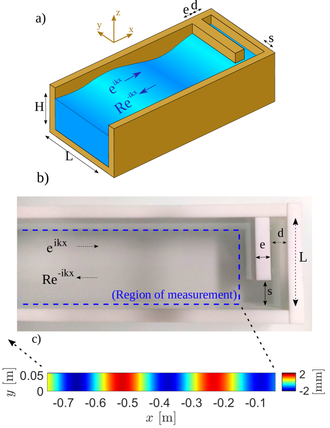
The resonator that we consider is composed of a small open cavity of depth at the extremity of a channel of width (Fig. 1). A gate of width delimits the open cavity connected to the channel through a thin guide corresponding to the resonator neck with an opening length . By varying the opening , the radiation damping of the resonator will change a lot: for it is totally open to leakage and for it will go to a closed resonator without leakage. Since the bathymetry is flat, with a finite depth , the surface elevation satisfies the Helmholtz equation
| (1) |
in which for a given frequency (harmonic regime ), the wavenumber is given by the dispersion relation of water waves
| (2) |
with the gravity and the water depth. In the following, we will be working in the low frequency regime, with , where only the planar mode can propagate in the channel. An incident wave impinges on the resonator which is at , such that the total wave in the channel can be written in the form
| (3) |
with the complex amplitude of the incident wave at and where is the reflection coefficient.
We first consider the lossless case; then, close to the resonance frequency, can be expressed as
| (4) |
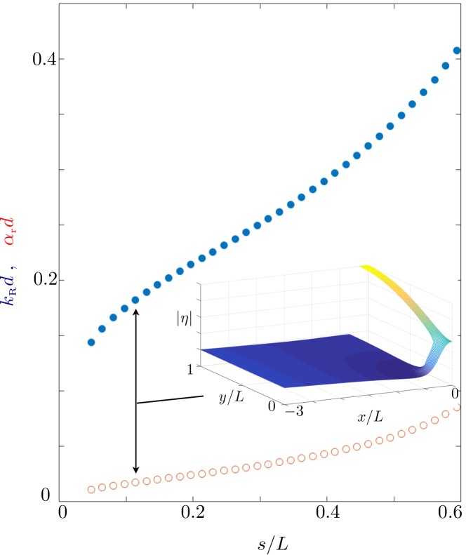
where corresponds to the complex resonance frequency of the resonator pagneux1 , where encapsulates the radiative damping. This complex resonance frequency has been computed numerically (with the pdetool Finite Element Method toolbox of Matlab) as a function of the resonator opening ; the results are shown in Fig. 2. We can observe that spans a broad range of values and it is thus confirmed that the chosen simple resonator offers a wide range of radiation damping. It is an important aspect because it means that it is a factor that we will be able to tune easily.
Then, a good approximation to take into account the intrinsic loss in the cavity can be obtained by simply shifting the numerator and the denominator by a positive viscous damping factor (as if )
| (5) |
We shall see that the above expressions (2) and (5) contain all the necessary to describe the critical coupling in our experiments. In every case, the point will be to try to obtain to get , the total absorption at the resonance frequency.
Experimental set-up and measuring technique – The water depth is set to cm; the channel is cm large and 1 m long. The dimensions of the resonator are 1 cm and variable opening from 0.3 to 3 cm. Waves are generated by a piston-type wavemaker driven by a linear motor in the range Hz with step Hz; their amplitudes are controlled precisely from 0.2 mm to 5 mm with step 0.1 mm. In this frequency range, only the plane wave is propagating ( m-1, whence ). The fields of surface elevation are measured using the optical Fourier Transform Profilometry (FTP) Cobelli et al. (2009); Maurel et al. (2009); Przadka et al. (2012). Sinusoidal fringes are projected by a digital projector over an area of cm2. The images of the free surface are collected by a camera, allowing for a spatial resolution given by the size of the projected pixel of 0.7 mm in both directions and a temporal resolution of fps given by the acquisition frequency of the camera. The record duration of s covers at least 20 periods for the lowest forcing frequency. From these space-time resolved measurements of the surface elevation , we extract the linear mode from a temporal Fourier decomposition
| (6) |
where is the forcing frequency and with integer. This allows us to quantify the nonlinearity of the waves and to calculate the reflection coefficient , far enough from the resonator (about cm in practice) by using a fit of equation (3). Eventually, the signal-to-noise ratio is reduced by averaging over the transverse direction afterwards the fit is performed to get . Note that the typical measured field reported in Fig. 1 shows that is indeed independent of .
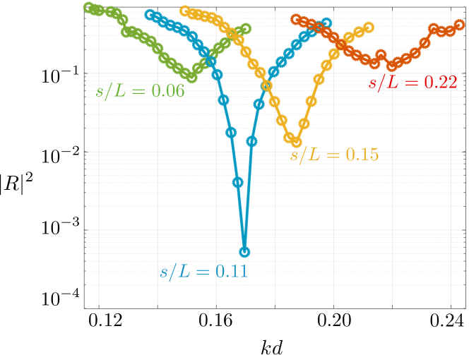
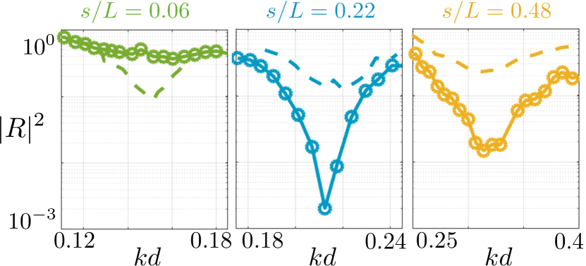
Critical coupling tuned by the geometry – To begin with, we consider the linear regime for water waves and play with the opening of the resonator to modify the critical coupling, trying to push towards in (5)). In our experiments, linear regime corresponds to wave amplitudes mm, where we found the nonlinearities to be weak and where our measurement technique is accurate. The Fig. 3 reports the measured reflectivity for 4 values of from 0.06 to 0.22. In each case, the reflectivity is smaller than unity because of the viscous losses and it has a minimum at the resonance frequency, in rough agreement with (5). As can be seen, this resonance frequency is controlled by the neck opening , resulting in the shift to higher frequencies when increasing , in agreement with the numerical results in Fig. 2.
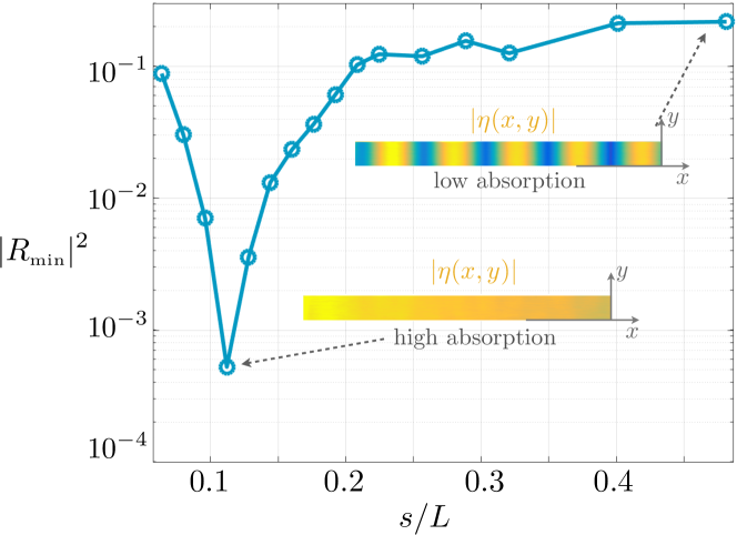
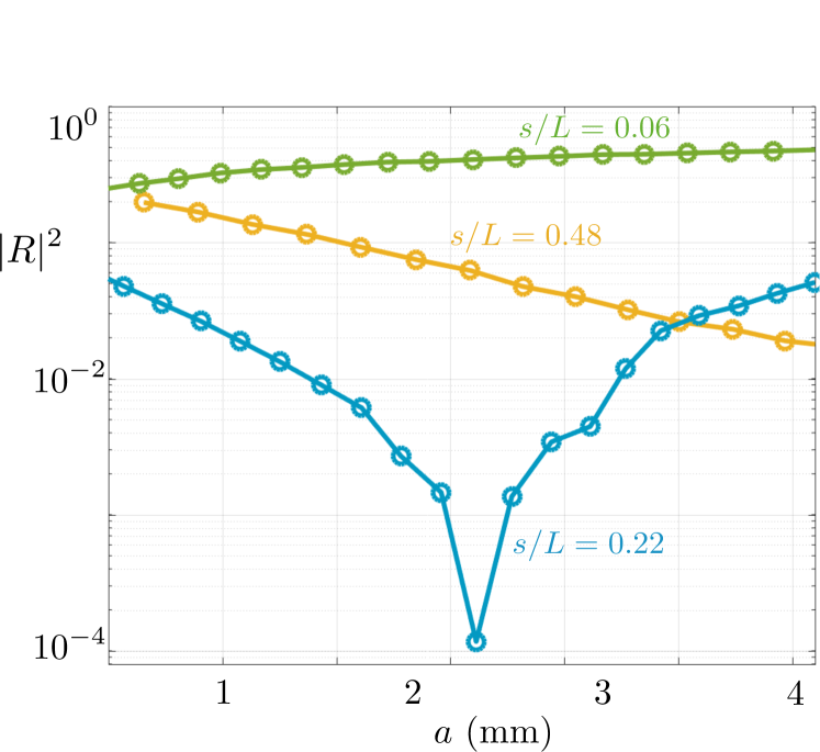
More interestingly, the minimum in the reflectivity is impacted by the value of the opening : this is what we use to achieve the critical coupling with zero reflectivity. To reach the total absorption, we perform a series of experiments varying with a spacing of mm and collect the . The result is reported in Fig. 4. The critical coupling is obtained at the minimum for 0.11 for , corresponding to a subwavelength ratio . The low reflection is further illustrated in the insets where we report the measured patterns of for at 0.48 and for at 0.11.
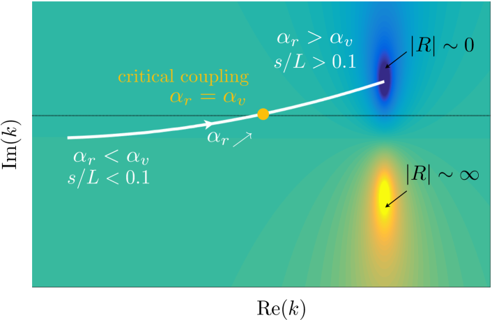
To interpret the findings of the Fig. 4, it is sufficient to come back to (5). Adopting a representation of in the complex map of , a zero of appears at some distance of the real axis. The plot reports a typical case for the highest value (high leakage); in this case, the radiative damping is higher than the viscous damping. Next, decreasing makes the radiative damping to decrease up to balance the viscous damping (yellow point realizing the critical damping). Eventually decreasing further the radiative damping moves the zero of in the lower half plane.
Critical coupling tuned by nonlinearities – It has been shown that water waves interacting with obstacles in the nonlinear regime experience an effective damping higher than that predicted in the linear regime, see e.g. Warnitchai and Pinkaew (1998). This is attributable to the energy taken by structures generated in the fluid, and the stronger are the nonlinearities the higher is the effective damping within Warnitchai and Pinkaew (1998) a linear dependence Morison et al. (1953). Hence, it is possible to increase the internal damping and to balance it with the radiative damping by increasing the amplitude of the waves. In other words, for the family of resonators which are strongly coupled to the exterior, it is possible to realize perfect absorption tuned by the nonlinearities. This critical coupling by nonlinear losses has been demonstrated recently for acoustic waves Achilleos et al. (2016).
We consider resonators with relative openings , and . We measure the reflectivity curves in the linear regime ( mm) and in the non linear regime (with mm for and mm for and 0.48); results are reported in Fig. 6. For , the reflectivity increases from the linear to the non linear regimes. This is expected since we already know from the study in the linear regime that for such weakly coupled resonator, the radiative damping was already weaker than the viscous damping in the linear regime (see Fig. 5); hence increasing this latter makes the things worse. Reversely, for and , the reflectivity reduces a fact also expected from the Fig. 5.
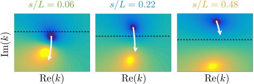
To go further, we modify with constant step the wave amplitude in the nonlinear regime up to mm (the wavemaker is controlled precisely with an amplitude step of 0.1 mm). We report as a function of the wave amplitude in Fig. 7. This representation complements that of the Fig. 6 at (, 0.21 and 0.3, respectively). Expectedly, for the resonator weakly coupled with the exterior (), the reflectivity increases with the nonlinearities since the system is getting away from the critical coupling. Next, both resonators and 0.48 are sufficiently coupled to the exterior, hence increasing the non linearities makes these systems to approach the critical coupling. However, the critical coupling is reached only for the resonator at . For , we see that we should increase further the nonlinearities to reach the critical coupling for that large opening. It is worth noting that for increasing the leakage with large produces low quality factor resonances, a fact which is recovered in the reflectivity curve in Fig. 6 with a decrease in occurring in a broad frequency range. Eventually, the scenario described above is illustrated further in Fig. 8 where the trajectory of the zeros of in the complex -plane is illustrated in the 3 cases.
In this work, we have demonstrated experimentally that we can obtain perfect wave absorption by tuning the geometry of a resonator, and consequently the radiation damping generated by this device. In addition, we demonstrated that the perfect absorption can be reached by tuning the incident wave amplitude (non linearity), which varies proportionally the intrinsic damping of the system. In this situation, when there is an excess of radiation damping (wide entrance to the resonator), by increasing the incident wave amplitude, we obtain broadband absorption due to the smaller quality factor of the resonance in this geometry. A natural continuation of this work would be to apply it to an energy conversion system. In this case, in order to maximize the energy conversion, we have to minimize the intrinsic losses of the system (water viscous losses), keeping most of the mechanical resistance coming from the conversion device.
E.M. acknowledges the support of CONICYT Becas Chile Doctorado. E.M., P.P., A.M. and V.P acknowledge the support Agence Nationale de la Recherche through the grant DYNAMONDE ANR-12-BS09-0027-01.
References
- Carrier et al. (1971) G. F. Carrier, R. P. Shaw, and M. Miyata, J. Appl. Mech. 38, 335 (1971).
- Mei et al. (2005) C. C. Mei, M. Stiassnie, and D. K.-P. Yue, Theory and applications of ocean surface waves, v.23 (World Scientific, 2005).
- (3) M. Cai, O. Painter, and K.J. Vahala, Phys. Rev. Lett. 85, 74 (2000).
- (4) A. Yariv, IEEE Phot. Tech. Lett. 14, 483 (2002).
- Landy et al. (2008) N. I. Landy, S. Sajuyigbe, J. J. Mock, D. R. Smith, and W. J. Padilla, Phys. Rev. Lett. 100, 207402 (2008).
- Watts et al. (2012) C. M. Watts, X. Liu, and W. J. Padilla, Adv. Mater. 24, OP98 (2012).
- Chong et al. (2010) Y. D. Chong, L. Ge, H. Cao, and A. D. Stone, Phys. Rev. Lett. 105, 053901 (2010).
- Luk et al. (2014) T. S. Luk, S. Campione, I. Kim, S. Feng, Y. C. Jun, S. Liu, J. B. Wright, I. Brener, P. B. Catrysse, S. Fan, and M. B. Sinclair, Phys. Rev. B 90, 085411 (2014).
- (9) J. R. Piper, V. Liu, and S. Fan, Appl. Phys. Lett. 104, 251110 (2014).
- Ma et al. (2014) G. Ma, M. Yang, S. Xiao, Z. Yang, and P. Sheng, Nat. Mater. 13, 873 (2014).
- (11) G. Ma, and P. Sheng, Sci. Adv. 2, e1501595 (2016).
- (12) M. Yang, and P. Sheng, Annu. Rev. Mater. Res., 47, 83 (2017).
- (13) H. Long, Y. Cheng, J. Tao, and X. Liu, Appl. Phys. Lett., 110, 023502 (2017).
- (14) T. Lee, and H. Iizuka, Appl. Phys. Lett., 113, 101903 (2018).
- Romero-Garci a et al. (2016a) V. Romero-Garcia, G. Theocharis, O. Richoux, A. Merkel, V. Tournat, and V. Pagneux, Sci. Rep. 6, 19519 (2016a).
- Romero-Garcia et al. (2016b) V. Romero-Garcia, G. Theocharis, O. Richoux, and V. Pagneux, J. Acoust. Soc. Am. 139, 3395 (2016b).
- Evans (1976) D. V. Evans, J. Fluid Mech. 77, 1 (1976).
- Mei (1976) C. C. Mei, J. Ship Res. 20, 63 (1976).
- Simon (1981) M. J. Simon, J. Fluid Mech. 104, 159 (1981).
- Crowley et al. (2013) S. Crowley, R. Porter, and D. Evans, J. Fluid Mech. 716, 566 (2013).
- Evans and Porter (2012) D. V. Evans and R. Porter, Phil. Trans. R. Soc. A 370, 315 (2012).
- Falnes (2007) J. Falnes, Mar. Struct. 20, 185 (2007).
- (23) S.W. Twu, and D.T. Lin, Coast. Eng. J. 15, 389 (1991)
- (24) I. Theocharis, E.N. Anastasaki, C.I. Moutzouris, and T. Giantsi, Ocean Eng. 38, 1967(2011).
- Martins-Rivas and Mei (2009) H. Martins-Rivas and C. C. Mei, J. Fluid Mech. 626, 395 (2009).
- (26) V. Pagneux, in Dynamic Localization Phenomena in Elasticity, Acoustics and Electromagnetism, CISM Springer, Vienna, Austria (2013) Vol. 547, p. 181.
- Cobelli et al. (2009) P. Cobelli, A. Maurel, V. Pagneux, and P. Petitjeans, Exp. Fluids 46, 1037 (2009).
- Maurel et al. (2009) A. Maurel, P. Cobelli, V. Pagneux, and P. Petitjeans, Appl. Opt. 48, 380 (2009).
- Przadka et al. (2012) A. Przadka, B. Cabane, V. Pagneux, A. Maurel, and P. Petitjeans, Exp. Fluids 52, 519 (2012).
- Warnitchai and Pinkaew (1998) P. Warnitchai and T. Pinkaew, Eng. Struct. 20, 593 (1998).
- Morison et al. (1953) J. Morison, J. W. Johnson, and M. P. O’Brien, in Proceedings of the Fourth Conference on Coastal Engineering, ASCE, New York (1953) p. 340.
- Achilleos et al. (2016) V. Achilleos, O. Richoux, and G. Theocharis, J. Acoust. Soc. Am. 140, EL94 (2016).