Interlayer fractional quantum Hall effect in a coupled graphene double-layer
Abstract
In two-dimensional (2D) electron systems under strong magnetic fields, interactions can cause fractional quantum Hall (FQH) effects [1, 2]. Bringing two 2D conductors to proximity, a new set of correlated states can emerge due to interactions between electrons in the same and opposite layers [3, 4, 5, 6]. Here we report interlayer correlated FQH states in a system of two parallel graphene layers separated by a thin insulator. Current flow in one layer generates different quantized Hall signals in the two layers. This result is interpreted by composite fermion (CF) theory[7] with different intralayer and interlayer Chern-Simons gauge-field coupling. We observe FQH states corresponding to integer values of CF Landau level (LL) filling in both layers, as well as “semi-quantized” states, where a full CF LL couples to a continuously varying partially filled CF LL. Remarkably, we also recognize a quantized state between two coupled half-filled CF LLs, attributable to an interlayer CF exciton condensate.
Department of Physics, Harvard University, Cambridge, Massachusetts 02138, USA
National Institute for Material Science, 1-1 Namiki, Tsukuba 305-0044, Japan
The energy levels of a non-interacting 2D electron system in a magnetic field are quantized into a discrete set of LLs with degeneracy proportional to the area of the system[6]. A key parameter in these systems is the LL filling factor , where is the electron density, is the magnetic field perpendicular to the layer, and the magnetic flux quantum , with the electron charge. Integer quantized Hall (IQH) effects occur when is an integer, where the Fermi level is in an energy gap between two LLs, and Coulomb interactions between electrons can often be ignored. However, Coulomb interactions have a dominant effect in partially filled LLs, lifting the LL degeneracy and causing new collective states of matter to appear at a certain set of fractional values of , which is known as the fractional quantum Hall (FQH) effect[1].
In single-layer systems, the most commonly observed FQH states can be understood in terms of the composite fermion (CF) picture[7]. Here, the electrons are each bound to even number () of quanta of an emergent Chern-Simons (CS) gauge field to form CFs, leaving only relatively weak residual interactions between them. Since the CS field combines with the applied magnetic field, the CFs experience an effective magnetic field , which is generally weaker than the original field . From this effective magnetic field, we can relate to the CF LL filling factor : . If is an integer, positive or negative, then the CF system is predicted to have an energy gap, and the electrons will be in a corresponding FQH state, with equal to a fraction with odd denominator. Because of this energy gap, the FQH state has vanishing longitudinal electric resistance and quantized Hall resistance[1] . FQH states also have quasiparticles with fractional charge and fractional quantum statistics (anyons), different from the statistics of bosons or fermions[2, 8].
The scope of quantum Hall physics further expands when we bring two layers close to each other, allowing strong Coulomb coupling between them, while suppressing a direct interlayer tunneling. One much-studied state in such systems is the interlayer-coherent IQH state, which was first observed for the total filling factor , where is the sum of the filling factors in the top and bottom layers[5, 9, 10]. Due to the Coulomb interaction, electrons in one layer are correlated with holes in the other. The ground state may be described as having a Bose condensate of interlayer excitons, added to a starting state in which one layer is empty while the other has a completely full Landau level. As the density of excitons can be varied continuously, the interlayer coherent state can exist over a wide range of values for the difference in layer occupations, while is fixed to be an integer.
Several experimental methods, including Coulomb drag[11, 12, 13], counterflow[14, 15], and tunneling measurements[16], have been exploited to demonstrate the interlayer correlation, superfluidity and coherence of exciton condensation. In Coulomb drag measurements, current is driven through one of the layers (drive layer), while the other layer (drag layer) is electrically not connected. When tunneling is absent, development of a large drag voltage proportional to provides a direct evidence for strong interlayer correlation. For , the Hall drag resistance is quantized to the same value as Hall resistance of the drive layer, , proving interlayer correlation and exciton superfluidity[5]. Previously, Coulomb drag study has been exclusively performed on integer exciton condensate states. In GaAs double quantum wells, is the only observed interlayer correlated state, while exciton condensation at several other integer have been reported in graphene double-layer system[12, 13]. Despite theoretical expectations[7, 17, 18, 6, 19, 20], no direct experimental observation of interlayer correlation at fractional total filling factor has been made thus far. The observed incompressible state at in double-layer or wide single-layer GaAs has been proposed to be the correlated Halperin (331) state[3], but without direct experimental verification[4, 9, 10, 21]. The delicacy of these expected interlayer FQH states demands extremely high sample quality.
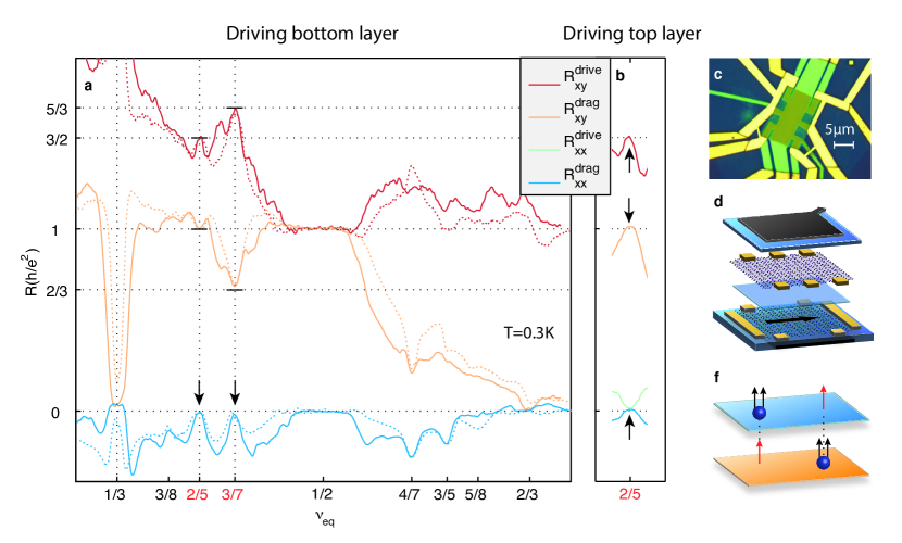
In the present study, we have fabricated monolayer graphene double-layer devices with top and bottom graphite gates. The dual graphite gates shield the graphene layers from impurities and contaminations, enabling lower disorder and more homogeneous samples[22]. The heterostructure, stacked all at once, is composed of two graphene layers separated by hexagonal boron nitride (hBN), with the graphite/hBN encapsulation layers at the top and the bottom (Fig. 1d, the topmost hBN layer not shown). The thickness of interlayer hBN is 2.5 nm, which allows strong interlayer Coulomb interaction while preventing direct tunnel coupling between the graphene layers. The stack is then etched into Hall bar shape and individual contacts on each layer are fabricated.
Coulomb drag measurements were first performed with both layers at the same carrier density () (Fig. 1a, b). The previously observed exciton condensate state [12, 13] can be clearly identified at , with quantized and vanishing . In this high quality sample, however, additional features with large drag responses are also observed away from , indicating that strong interlayer coupling persists, thereby enabling additional interlayer correlated states (Fig. 1a). In particular, we observe vanishing at (data for is found in SI), which suggests that incompressible states are developed at these filling factors. Among them, and appear as trivial single layer FQH states, evident from vanishing . We thus focus our attention first on and particularly, which are two most prominent states that produce quantized Hall responses in the drive and drag layer. Interestingly, for these states, the two Hall resistance, and , are quantized to different fractional values. For , we observe and while for , and , respectively (from now on we use the unit of resistance quantum for the quantized resistance values). From these numbers, we note that the sum of Hall resistance in the drive and drag layer , as if a portion of Hall voltage is shifted from the drive layer to the drag layer.
We demonstrate that state can be understood with a generalized CF description extended to double-layer systems. Here, we introduce multiple species of gauge field, coupling fermions in different layers as well as in the same layer. For our purposes, we attach two intralayer flux quanta and one interlayer flux quantum to each electron, so that a CF in a given layer sees two flux quanta attached to every electron in the same layer, but only one flux quantum attached to electrons in the other layer (Fig. 1f). We only work in region, and we assume that electrons are spin and valley polarized. By generalizing the single layer CF picture, it is natural to define CF filling factors and for the top and bottom layers respectively. These are defined as the ratio between the fermion density in a given layer to the effective magnetic field felt by CFs in that layer (see SI):
| (1) |
Inverting Eq. 1, the LL filling factors for electrons in the two layers will then be given by
| (2) |
In the case where the layers have equal density, this formula simplifies to , where .
The experimentally observed interlayer correlated state corresponds to the composite fermion filling factors . Since the CFs in both layers are correlated, the Hall signal in both layers must be correlated as well. Using the CS field calculation, we find that the double layer Hall resistivity tensor obeys (see SI for derivation):
| (3) |
In this equation, is the Hall resistivity matrix in the unit of resistance quantum, which contains two contributing terms: originates from the motion of the CS flux considering the two intralayer flux quanta and one interlayer flux quantum, while is caused by Hall effect of CFs. At , Eq. (3) produces and , matching the experimental observations in Fig. 1a,b.
Applying similar CF formalism discussed above (Eq.1) to , however, we obtain , indicating that two half-filled CF LLs are involved in this state. A half-filled CF LL by itself should not develop an incompressible state. Moreover, if we were to enforce Eq. (3) for these values of and , we would predict and , which is in strong disagreement with the experimentally observed values, and , respectively.
In order to correct the weakly interacting CF model presented above for half-filled CF LLs, we can draw an analogy between the half-filled CF double-layer system to the half-filled electron double-layer system, in which an exciton condensate can be formed. If we assume pairing between CFs in one layer and CF holes in the second layer, the CF Hall resistivity tensor becomes
| (4) |
Inserting Eq. (4) into Eq. (3), we obtain and , which agrees with our experimental observations, thus suggesting the CF exciton condensation phase is indeed responsible for (Further discussion of CF paring in half-filled CF LLs can be found in the SI).
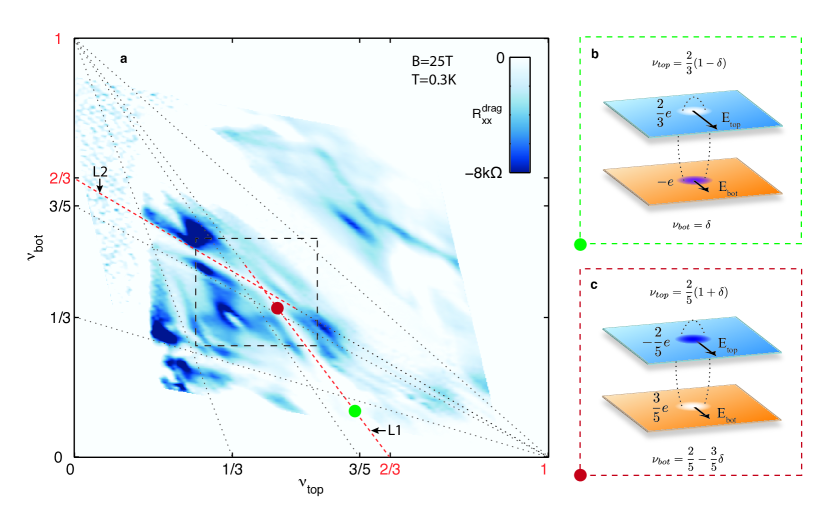
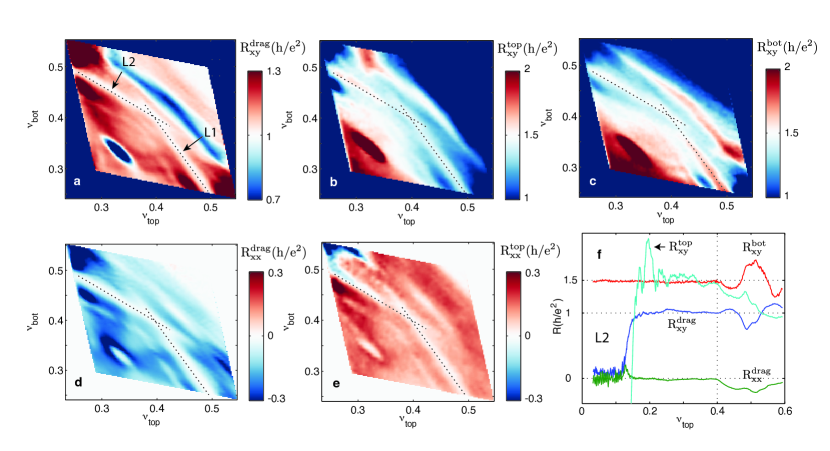
Away from equal filling status, Fig. 2a shows that the vanishing persists along the segments of two symmetric lines (labeled by L1 and L2) that intersect at . The line L2 has a slope of -2/3 and traces from () = (0, 2/3) to (1, 0), while L1 is the inverse. We find that the longitudinal drag vanishes and Hall drag remain quantized along these lines, as shown in Fig. 3a&d, indicating the strong interlayer interaction persists along these line segments. Unlike the quantized interlayer drag resistance, which is layer-independent by the Onsager relation, we find that the drive Hall resistance depends on which layer we measure. For example, along L2, we find driving the bottom layer exhibits QHE with and . However, when we drive the top layer along L2, and is not quantized. Along L1, the role of the top and bottom layers is reversed. The experimental observed behaviors of all the resistance components along L1 and L2 are summarized in Table. 1.
We note that along L1 or L2, the composite fermion filling factor of one of the layers ( or ) remains at while the other can change continuously. For example, for , the filling factors given by Eq. (2) satisfy the expression of L2: (). In principle, a series of discrete incompressible FQH states can be formed along this line, corresponding to various positive and negative integer values in Eq. (2). These should all exhibit vanishing longitudinal resistance, quantized and , which do not depend on , while the quantized values of would depend on the value of . What originally surprised us, however, is that the experimentally observed quantization of and , together with vanishing and , exists continuously along an entire segment of L2, even when is not an integer.
We now understand the above results as follows. For a general point on the line segment L2 (i.e. fixed ), there is an energy gap for adding or removing a CF of type B (), but not of type A (). Thus, while the state should not be as stable as at a point where CF filling factors and are both integers, so that both species of CF are gapped, it should nevertheless be more stable than at a nearby points where both CF filling factors are fractions. Therefore, it is plausible that CF states along a line where one of (, ) is an integer should be good candidates for the true ground state at the corresponding filing fractions. We call such states semi-quantized, as one CF filling factor is fixed but the other can vary continuously.
To understand transport properties in a semi-quantized state, we first note that in the absence of CF scattering or of pinning by impurities, there would be no longitudinal resistance and the Hall resistances would be given by Eq. (3), even in the absence of an energy gap. For the semi-quantized state along L2 (), if an electrical current is driven on the bottom layer, then the current can be carried entirely by CFs of type B (bottom drive), with stationary CFs of type A (top, drag layer). Since type B CFs are contained in a filled CF-LL, the current is carried without dissipation. Furthermore, as there is no tendency for flow of the type A CFs, a small density of impurities will have no effect, leading to quantization and . On the other hand, if current is applied to the top layer, CFs of type A will be forced to move. If CFs in the partially filled CF LL are not pinned by impurities, they will participate in the motion, and the they can be scattered by impurities. This will lead to a longitudinal resistance, and deviations from the result predicted by Eq. (3), except in the case where is so close to an integer value that the small density of excess CFs is pinned by impurities.
An alternative approach to understanding properties of the states along L1 and L2 is to begin with the balanced quantized state at , and add quasi-holes to this state. Elementary quasi-holes in this state have total charge , with in one layer and in the other. The addition of one or another type of quasi-hole will move the system along the line L1 or L2, in a direction decreasing the total filling factor. The relative stability of states on the two line segments can be understood considering the energy cost for quasi-holes versus quasiparticles (See the SI for more discussion).
Finally, we turn to the state at and the lines through it. The state may be described in our CF language by . As discussed in the SI, the state is also equivalent to the Halperin (331) state which has been proposed as a possible explanation for the FQH state at in wide GaAs quantum wells. The line L3 in Fig. S2, which passes through this point, corresponds to with continuously varying . Although there appears to be a well-developed FQH state at with along this line, corresponding to the values , there does not appear to be a line of semi-quantized states between these two points. The absence of the continuous semi-quantization along these lines suggests that the stabilization of interlayer correlated CF state requires microscopic consideration of the energetics of the quasiparticle addition to the system (see SI).
0.1 Sample fabrication
The hBN-graphite-hBN-graphene-hBN-graphene-hBN-graphite (from top to bottom) stack are prepared by mechanical exfoliation and van derWaals (vdW) transfer technique. The shape of graphene and graphite are carefully chosen and arranged so that we can use the overlapped part as the main channel area, while fabricating individual contacts on each layer at the regions with just one conducting layer. A square-shaped top graphene layer is chosen, while we pick strip-shaped bottom graphene and bottom graphite, that are narrower but longer than the top graphene. We align the bottom graphite and bottom graphene into a cross, while keeping the overlapped area inside the top graphene square. The top graphite covers everything after stacking but is etched into the same shape as bottom graphite. We then etch the stack into final device geometry and fabricate Cr/Pd/Au contact on all the graphene and graphite layers. Last, we grow 20-30nm ALD Al2O3, and then deposit contact gates above top layer graphene lead to increase the contact transparency.
0.2 Coulomb drag measurement
We perform Coulomb drag measurement with 2nA excitation current on the drive layer using lockin amplifiers at 17.7Hz. We used a symmetric bias scheme to eliminate any possible interlayer bias effect. In this scheme, we apply positive bias +V on the source and -V on the drain (both on the drive layer). The drag layer is open circuit but with one of the contact connected to the ground through 1MOhm resistor to allow charges to flow in and out of the layer for gating effect. Using ALD contact gate and silicon backgate, we dope the lead area of both layers to high carrier density and matching carrier type with the channel. The measurements are done in a He3 cryostat at 300mK.
References
- [1] Tsui, D. C., Stormer, H. L. & Gossard, A. C. Two-dimensional magnetotransport in the extreme quantum limit. Physical Review Letters 48, 1559–1562 (1982).
- [2] Laughlin, R. B. Anomalous quantum Hall effect: An incompressible quantum fluid with fractionally charged excitations. Physical Review Letters 50, 1395–1398 (1983).
- [3] Halperin, B. I. Theory of the quantized Hall conductance. Helv. Phys. Acta 56:75–104 56, 75–104 (1983).
- [4] Chakraborty, T. & Pietiläinen, P. Fractional quantum hall effect at half-filled landau level in a multiple-layer electron system. Physical Review Letters 59, 2784–2787 (1987).
- [5] Eisenstein, J. Exciton Condensation in Bilayer Quantum Hall Systems. Annual Review of Condensed Matter Physics 5, 159–181 (2014).
- [6] Jain, J. Composite fermions, vol. 9780521862 (Cambridge University Press, Cambridge, 2007). URL http://ebooks.cambridge.org/ref/id/CBO9780511607561.
- [7] Jain, J. K. Composite-fermion approach for the fractional quantum Hall effect. Physical Review Letters 63, 199–202 (1989).
- [8] Halperin, B. I. Statistics of Quasiparticles and the Hierarchy of Fractional Quantized Hall States. Physical Review Letters 52, 1583–1586 (1984).
- [9] Suen, Y. W., Engel, L. W., Santos, M. B., Shayegan, M. & Tsui, D. C. Observation of a =1/2 fractional quantum Hall state in a double-layer electron system. Physical Review Letters 68, 1379–1382 (1992).
- [10] Eisenstein, J. P., Boebinger, G. S., Pfeiffer, L. N., West, K. W. & He, S. New fractional quantum Hall state in double-layer two-dimensional electron systems. Physical Review Letters 68, 1383–1386 (1992).
- [11] Kellogg, M., Spielman, I. B., Eisenstein, J. P., Pfeiffer, L. N. & West, K. W. Observation of quantized Hall drag in a strongly correlated bilayer electron system. Physical review letters 88, 126804 (2002).
- [12] Liu, X., Watanabe, K., Taniguchi, T., Halperin, B. I. & Kim, P. Quantum Hall drag of exciton condensate in graphene. Nature Physics 13, 746–750 (2017).
- [13] Li, J. I., Taniguchi, T., Watanabe, K., Hone, J. & Dean, C. R. Excitonic superfluid phase in double bilayer graphene. Nature Physics 13, 751–755 (2017).
- [14] Kellogg, M., Eisenstein, J. P., Pfeiffer, L. N. & West, K. W. Vanishing Hall resistance at high magnetic field in a double-layer two-dimensional electron system. Phys. Rev. Lett. 93, 36801 (2004).
- [15] Tutuc, E., Shayegan, M. & Huse, D. A. Counterflow measurements in strongly correlated GaAs hole bilayers: Evidence for electron-hole pairing. Physical Review Letters 93, 036802–1 (2004).
- [16] Spielman, I. B., Eisenstein, J. P., Pfeiffer, L. N. & West, K. W. Resonantly enhanced tunneling in a double layer quantum hall ferromagnet. Physical Review Letters 84, 5808–5811 (2000).
- [17] Yoshioka, D., MacDonald, A. H. & Girvin, S. M. Fractional quantum Hall effect in two-layered systems. Physical Review B 39, 1932–1935 (1989).
- [18] Scarola, V. W. & Jain, J. K. Phase diagram of bilayer composite fermion states. Physical Review B - Condensed Matter and Materials Physics 64, 853131–8531310 (2001).
- [19] Barkeshli, M. & Wen, X.-G. Non-Abelian two-component fractional quantum Hall states. Physical Review B 82, 233301 (2010).
- [20] Geraedts, S., Zaletel, M. P., Papić, Z. & Mong, R. S. K. Competing Abelian and non-Abelian topological orders in = 1 / 3 + 1 / 3 quantum Hall bilayers. Physical Review B 91, 205139 (2015).
- [21] He, S., Das Sarma, S. & Xie, X. C. Quantized Hall effect and quantum phase transitions in coupled two-layer electron systems. Physical Review B 47, 4394–4412 (1993).
- [22] Zibrov, A. A. et al. Tunable interacting composite fermion phases in a half-filled bilayer-graphene Landau level. Nature 549, 360–364 (2017).
The major experimental work is supported by DOE (DE-SC0012260). The theoretical analysis was supported by the Science and Technology Center for Integrated Quantum Materials, NSF Grant No. DMR-1231319. P.K. acknowledges partial support from the Gordon and Betty Moore Foundation’s EPiQS Initiative through Grant GBMF4543. K.W. and T.T. acknowledge supports from the Elemental Strategy Initiative conducted by the MEXT, Japan and the CREST(JPMJCR15F3), JST. A portion of this work was performed at the National High Magnetic Field Laboratory, which is supported by the National Science Foundation Cooperative Agreement No. DMR-1157490* and the State of Florida. Nanofabrication was performed at the Center for Nanoscale Systems at Harvard, supported in part by an NSF NNIN award ECS-00335765. In preparation of this manuscript, we are aware of related work done by J.I.A Li et al. We thank Bernd Rosenow, J.I.A Li and C. Dean for helpful discussion.
X.L. and P.K. conceived the experiment. X.L. and Z.H. fabricated the samples and performed the measurements. X.L. analyzed the data. B.I.H conducted the theoretical analysis. X.L., B.I.H. and P.K. wrote the paper. K.W. and T.T. supplied hBN crystals.
Correspondence and requests for materials should be addressed to P. Kim (email: pkim@physics.harvard.edu).
| L1 | 0 | 1 | 0 | 1.5 | 0 | non-quantized. |
| L2 | 0 | 1 | 0 | non-quantized | 0 | 1.5 |